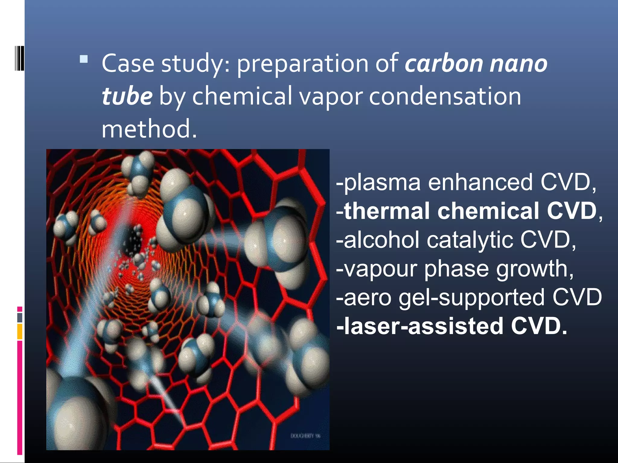
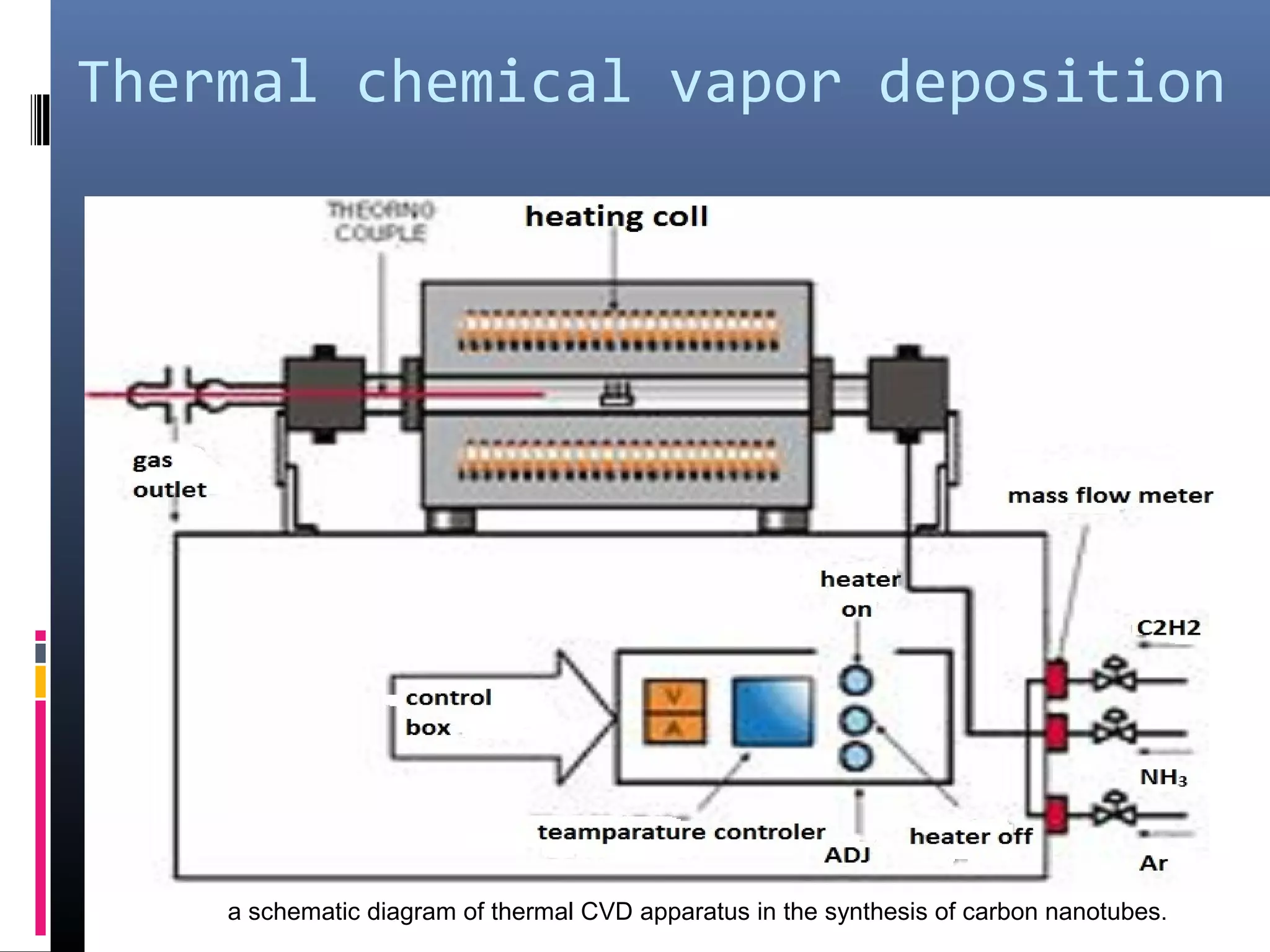
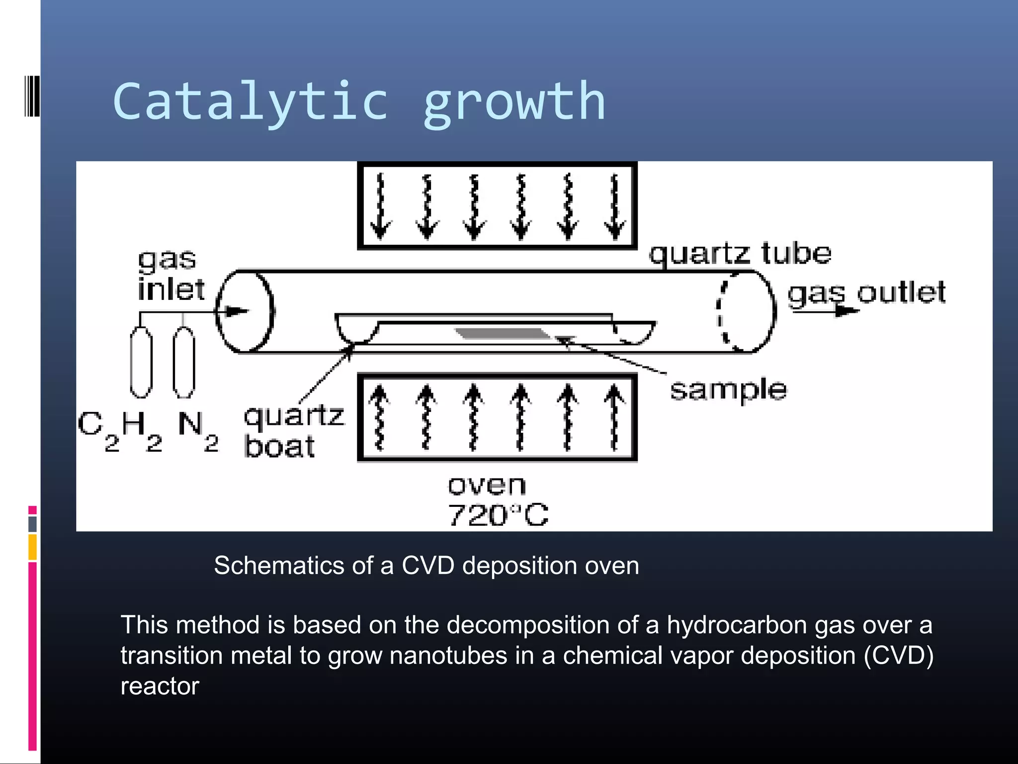
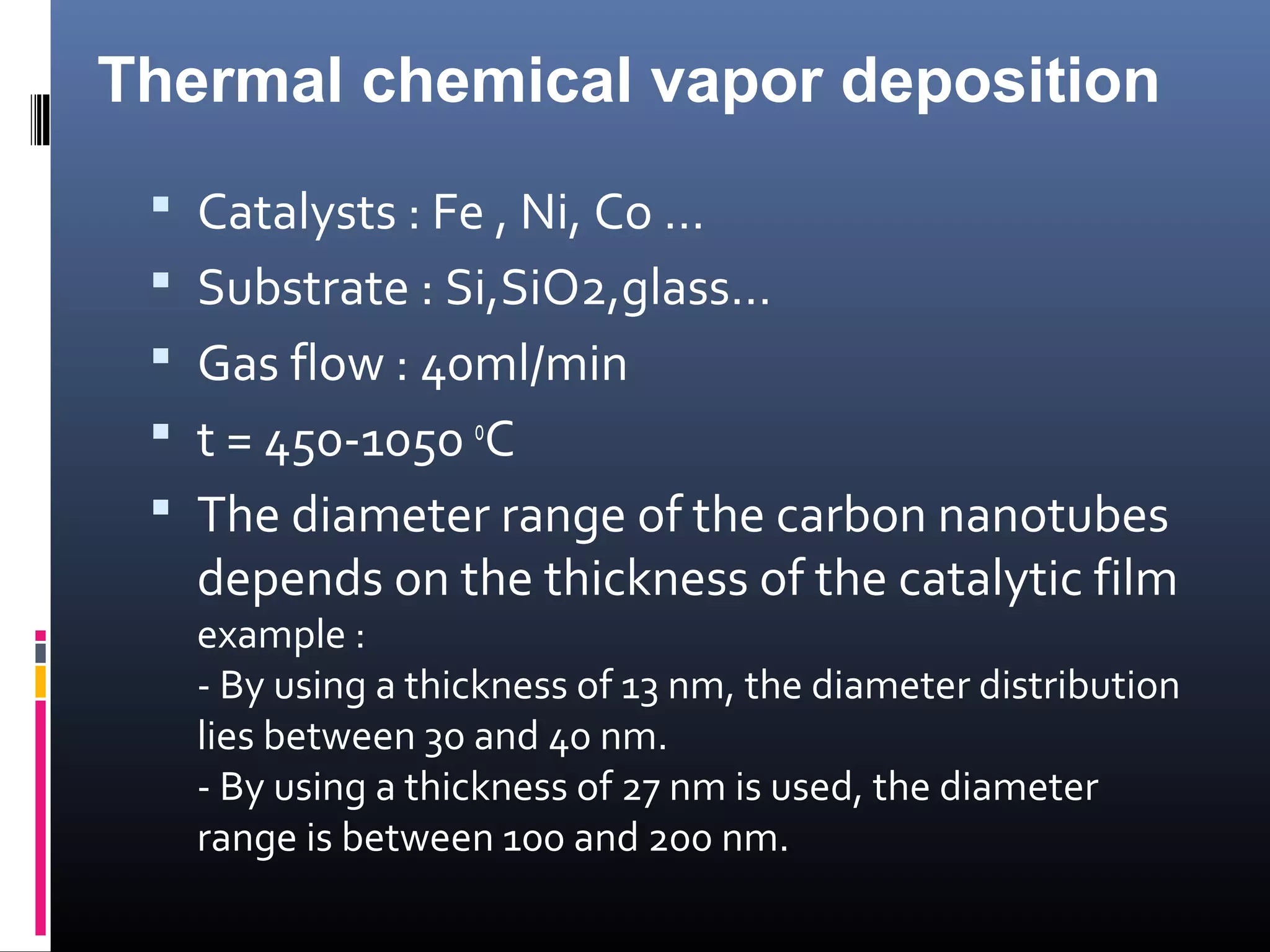
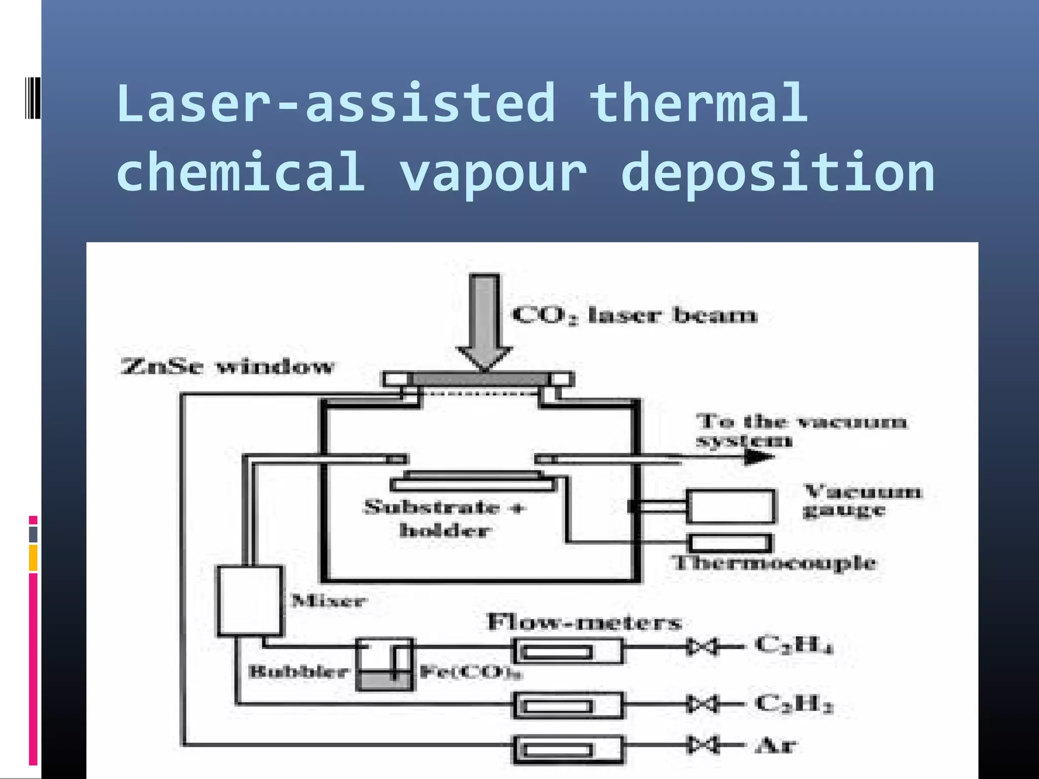
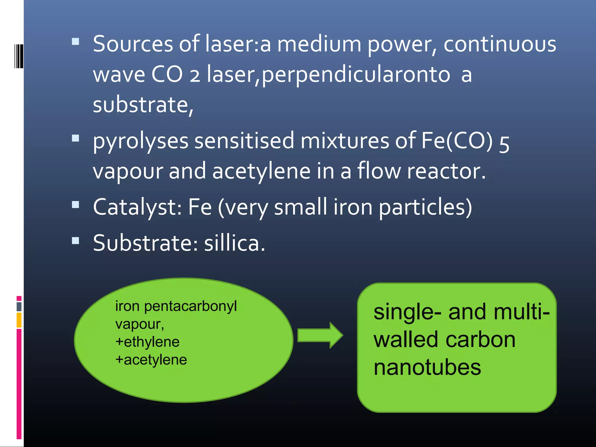
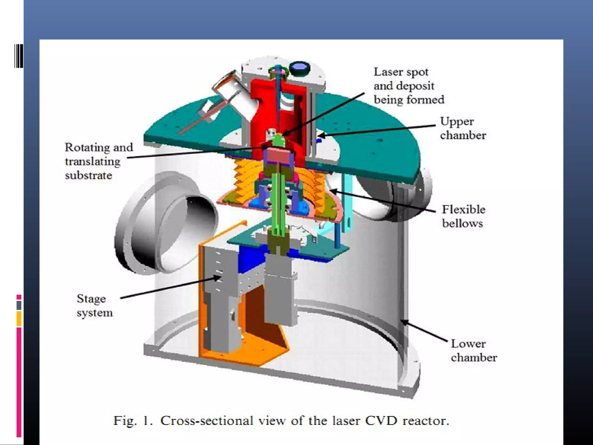
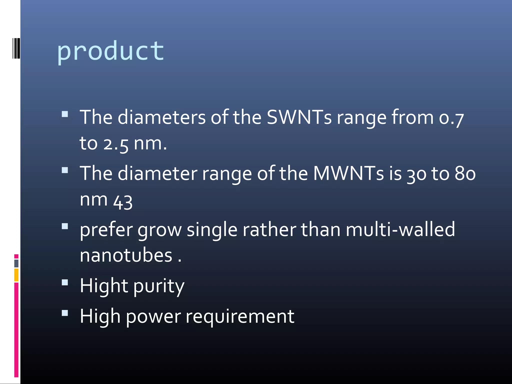
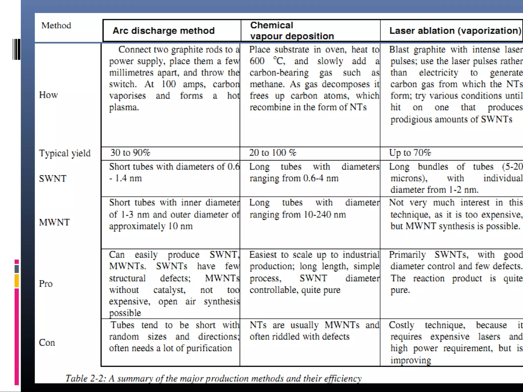
Class: Material Science Engineering
Student : Hoang Van Tien


                                      Hanoi -2012
Nanomaterials

     Top -down approaches
     Bottom-up approaches
     Functional approaches
     Biomimetic approaches
     Speculative
Bottom up synthesis

 Solgel synthesis
 Precipitation
 Physical vapor synthesis
 Chemical vapor condensation
 Spray conversion processing
Chemical vapor condensation
 Chemical vapor deposition (CVD) synthesis is
  achieved by putting a carbon source in the gas
  phase and using an energy source, such as a
  plasma or a resistively heated coil, to transfer
  energy to a gaseous carbon molecule.
 Types :plasma enhanced CVD, thermal
  chemical CVD, alcohol catalytic CVD, vapour
  phase growth, aero gel-supported CVD and
  laser-assisted CVD.
 -Gaseous carbon sources : methane, carbon
  monoxide and acetylene…
 Case study: preparation of carbon nano
 tube by chemical vapor condensation
 method.
                     -plasma enhanced CVD,
                     -thermal chemical CVD,
                     -alcohol catalytic CVD,
                     -vapour phase growth,
                     -aero gel-supported CVD
                     -laser-assisted CVD.
the growth mechanism
process

 The energy source is used to "crack" the
  molecule into reactive atomic carbon.
 The carbon diffuses towards the substrate,
  which is heated and coated with a catalyst
  where it will bind.
 Carbon nanotubes will be formed if the
  proper parameters are maintained.
positional control on
nanometre scale
 CVD carbon nanotube synthesis is essentially
  a two-step process :
  -catalyst preparation
  -actual synthesis of the nanotube.
 The catalyst is generally prepared by sputtering a
  transition metal onto a substrate and then using either
  chemical etching or thermal annealing to induce catalyst
  particle nucleation.
 Thermal annealing results in cluster formation on the
  substrate, from which the nanotubes will grow.
Thermal chemical vapor deposition


    a schematic diagram of thermal CVD apparatus in the synthesis of carbon nanotubes.
Catalytic growth


        Schematics of a CVD deposition oven

This method is based on the decomposition of a hydrocarbon gas over a
transition metal to grow nanotubes in a chemical vapor deposition (CVD)
reactor
Thermal chemical vapor deposition
  Catalysts : Fe , Ni, Co …
  Substrate : Si,SiO2,glass…
  Gas flow : 40ml/min
  t = 450-1050 oC
  The diameter range of the carbon nanotubes
   depends on the thickness of the catalytic film
   example :
   - By using a thickness of 13 nm, the diameter distribution
   lies between 30 and 40 nm.
   - By using a thickness of 27 nm is used, the diameter
   range is between 100 and 200 nm.
product

 Advantages:
 -Typical yield: 20-100%
 - Long tubes with diameter ranging from 10-240 nm for
 MWNT (multi walled nanotubes) and 0.6-4 nm for
 SWNT( single walled nanotubes).
 - Easiest to scale up to industrial production; long length,
 simple process, SWNT diameter controllable, quite pure
 Disadvantages:
 - large diameter range    =>>>poorly controlled.
 -often riddled with defects
Laser-assisted thermal
chemical vapour deposition
 Sources of laser:a medium power, continuous
  wave CO 2 laser,perpendicularonto a
  substrate,
 pyrolyses sensitised mixtures of Fe(CO) 5
  vapour and acetylene in a flow reactor.
 Catalyst: Fe (very small iron particles)
 Substrate: sillica.

    iron pentacarbonyl
    vapour,
                             single- and multi-
    +ethylene                walled carbon
    +acetylene
                             nanotubes
product

 The diameters of the SWNTs range from 0.7
    to 2.5 nm.
   The diameter range of the MWNTs is 30 to 80
    nm 43
   prefer grow single rather than multi-walled
    nanotubes .
   Hight purity
   High power requirement
Purification

 The main impurities :graphite (wrapped up) sheets,
  amorphous carbon, metal catalyst and the smaller
  fullerenes…
 Rules :
  -separate the SWNTs from the impurities
  - give a more homogeneous diameter or size distribution.

 The techniques that will be discussed are oxidation, acid
  treatment, annealing, ultrasonication, micro filtration,
  ferromagnetic separation, cutting, functionalisation and
  chromatography techniques.
applications
Nanotubes are rolled-up graphene sheets, and graphene is
one of the stiffest materials when subjected to deformations
parallel to the sheet.
⇒nanotubes show exceptional mechanical properties,
especially a high strength-to-weight ratio.

Applications:

 Field emission
 Field emission
 Nanotube sensors
 Nanotube transistors
 Nanotubes as SPM tips….
Schematics of a nanotube transistor, with some measurements.
Use of a MWNT as AFM tip. VGCF stands for Vapour Grown Carbon Fibre.
At the centre of this fibre the MWNT forms the tip
sources

1. D.A.Bochvar and E.G.Gal'pern,
   Dokl.Akad.Nauk.USSR, 209, (610, 1973 )
2.http://www.ou.edu/engineering/nanotube, 2003
3. http://nanotube.msu.edu/
4.http://www.pa.msu.edu/cmp/csc/nanotube.htm5
   5.http://en.wikipedia.org/wiki/Carbon_nanotube
   6.
   http://students.chem.tue.nl/carbonnanotubes/applica
Nanomaterials present

Nanomaterials present

  • 1.
    Class: Material ScienceEngineering Student : Hoang Van Tien Hanoi -2012
  • 2.
    Nanomaterials  Top -down approaches  Bottom-up approaches  Functional approaches  Biomimetic approaches  Speculative
  • 3.
    Bottom up synthesis Solgel synthesis  Precipitation  Physical vapor synthesis  Chemical vapor condensation  Spray conversion processing
  • 4.
    Chemical vapor condensation Chemical vapor deposition (CVD) synthesis is achieved by putting a carbon source in the gas phase and using an energy source, such as a plasma or a resistively heated coil, to transfer energy to a gaseous carbon molecule.  Types :plasma enhanced CVD, thermal chemical CVD, alcohol catalytic CVD, vapour phase growth, aero gel-supported CVD and laser-assisted CVD. -Gaseous carbon sources : methane, carbon monoxide and acetylene…
  • 5.
     Case study:preparation of carbon nano tube by chemical vapor condensation method. -plasma enhanced CVD, -thermal chemical CVD, -alcohol catalytic CVD, -vapour phase growth, -aero gel-supported CVD -laser-assisted CVD.
  • 6.
  • 7.
    process  The energysource is used to "crack" the molecule into reactive atomic carbon.  The carbon diffuses towards the substrate, which is heated and coated with a catalyst where it will bind.  Carbon nanotubes will be formed if the proper parameters are maintained.
  • 8.
    positional control on nanometrescale  CVD carbon nanotube synthesis is essentially a two-step process : -catalyst preparation -actual synthesis of the nanotube.  The catalyst is generally prepared by sputtering a transition metal onto a substrate and then using either chemical etching or thermal annealing to induce catalyst particle nucleation.  Thermal annealing results in cluster formation on the substrate, from which the nanotubes will grow.
  • 9.
    Thermal chemical vapordeposition a schematic diagram of thermal CVD apparatus in the synthesis of carbon nanotubes.
  • 10.
    Catalytic growth Schematics of a CVD deposition oven This method is based on the decomposition of a hydrocarbon gas over a transition metal to grow nanotubes in a chemical vapor deposition (CVD) reactor
  • 11.
    Thermal chemical vapordeposition  Catalysts : Fe , Ni, Co …  Substrate : Si,SiO2,glass…  Gas flow : 40ml/min  t = 450-1050 oC  The diameter range of the carbon nanotubes depends on the thickness of the catalytic film example : - By using a thickness of 13 nm, the diameter distribution lies between 30 and 40 nm. - By using a thickness of 27 nm is used, the diameter range is between 100 and 200 nm.
  • 12.
    product  Advantages: -Typicalyield: 20-100% - Long tubes with diameter ranging from 10-240 nm for MWNT (multi walled nanotubes) and 0.6-4 nm for SWNT( single walled nanotubes). - Easiest to scale up to industrial production; long length, simple process, SWNT diameter controllable, quite pure  Disadvantages: - large diameter range =>>>poorly controlled. -often riddled with defects
  • 13.
  • 14.
     Sources oflaser:a medium power, continuous wave CO 2 laser,perpendicularonto a substrate,  pyrolyses sensitised mixtures of Fe(CO) 5 vapour and acetylene in a flow reactor.  Catalyst: Fe (very small iron particles)  Substrate: sillica. iron pentacarbonyl vapour, single- and multi- +ethylene walled carbon +acetylene nanotubes
  • 16.
    product  The diametersof the SWNTs range from 0.7 to 2.5 nm.  The diameter range of the MWNTs is 30 to 80 nm 43  prefer grow single rather than multi-walled nanotubes .  Hight purity  High power requirement
  • 17.
    Purification  The mainimpurities :graphite (wrapped up) sheets, amorphous carbon, metal catalyst and the smaller fullerenes…  Rules : -separate the SWNTs from the impurities - give a more homogeneous diameter or size distribution.  The techniques that will be discussed are oxidation, acid treatment, annealing, ultrasonication, micro filtration, ferromagnetic separation, cutting, functionalisation and chromatography techniques.
  • 19.
    applications Nanotubes are rolled-upgraphene sheets, and graphene is one of the stiffest materials when subjected to deformations parallel to the sheet. ⇒nanotubes show exceptional mechanical properties, especially a high strength-to-weight ratio. Applications:  Field emission  Field emission  Nanotube sensors  Nanotube transistors  Nanotubes as SPM tips….
  • 20.
    Schematics of ananotube transistor, with some measurements.
  • 21.
    Use of aMWNT as AFM tip. VGCF stands for Vapour Grown Carbon Fibre. At the centre of this fibre the MWNT forms the tip
  • 22.
    sources 1. D.A.Bochvar andE.G.Gal'pern, Dokl.Akad.Nauk.USSR, 209, (610, 1973 ) 2.http://www.ou.edu/engineering/nanotube, 2003 3. http://nanotube.msu.edu/ 4.http://www.pa.msu.edu/cmp/csc/nanotube.htm5 5.http://en.wikipedia.org/wiki/Carbon_nanotube 6. http://students.chem.tue.nl/carbonnanotubes/applica

Editor's Notes

  • #7 Carbon nanotubes are generally produced by three main techniques, arc discharge, laser ablation and chemical vapour deposition. The exact atmospheric conditions depend on the technique used, later on, these will be explained for each technique as they are specific for a technique. The actual growth of the nanotube seems to be the same for all techniques mentioned. There are several theories on the exact growth mechanism for nanotubes. One theory13 postulates that metal catalyst particles are floating or are supported on graphite or another substrate. It presumes that the catalyst particles are spherical or pear-shaped, in which case the deposition will take place on only one half of the surface (this is the lower curvature side for the pear shaped particles). The carbon diffuses along the concentration gradient and precipitates on the opposite half, around and below the bisecting diameter. However, it does not precipitate from the apex of the hemisphere, which accounts for the hollow core that is characteristic of these filaments. For supported metals, filaments can form either by ‘extrusion (also known as base growth)’ in which the nanotube grows upwards from the metal particles that remain attached to the substrate, or the particles detach and move at the head of the growing nanotube, labelled ‘tip-growth’. Depending on the size of the catalyst particles, SWNT or MWNT are grown. In arc discharge, if no catalyst is present in the graphite, MWNT will be grown on the C2-particles that are formed in the plasma. Có một số lý thuyết về cơ chế tăng trưởng chính xác cho các ống nano. Một giả thuyết  13  mặc nhiên cho rằng các hạt chất xúc tác là kim loại nổi hoặc được hỗ trợ trên than chì hoặc chất nền khác. Nó giả định rằng các hạt chất xúc tác có hình cầu hoặc hình quả lê, trong trường hợp sự lắng đọng sẽ diễn ra vào chỉ có một nửa của bề mặt (điều này là mặt cong thấp hơn cho các hạt hình quả lê). Carbon khuếch tán dọc theo gradient nồng độ và kết tủa trên một nửa ngược lại, xung quanh và bên dưới đường kính bisecting. Tuy nhiên, nó không kết tủa từ đỉnh của bán cầu, chiếm cốt lõi rỗng đó là đặc trưng của những sợi. Đối với kim loại hỗ trợ, sợi có thể hình thành bằng cách "ép (còn được gọi là tăng trưởng cơ sở), trong đó các ống nano phát triển lên từ các hạt kim loại vẫn còn gắn liền với bề mặt, hoặc các hạt tách ra và di chuyển ở phần đầu của ống nano đang phát triển, có nhãn "tip tăng trưởng". Tùy thuộc vào kích thước của các hạt chất xúc tác, SWNT hoặc các MWNT được trồng. Trong phóng điện hồ quang, nếu không có chất xúc tác có mặt trong than chì, MWNT sẽ được trồng trên các C  2  hạt được hình thành trong huyết tương.
  • #10 In this method Fe, Ni, Co or an alloy of the three catalytic metals is initially deposited on a substrate. After the substrate is etched in a diluted HF solution with distilled water, the specimen is placed in a quartz boat. The boat is positioned in a CVD reaction furnace, and nanometre-sized catalytic metal particles are formed after an additional etching of the catalytic metal film using NH 3  gas at a temperature of 750 to 1050 o  C. As carbon nanotubes are grown on these fine catalytic metal particles in CVD synthesis, forming these fine catalytic metal particles is the most important process.
  • #14 continuous wave CO 2  laser, which was perpendicularly directed onto a substrate, pyrolyses sensitised mixtures of Fe(CO) 5  vapour and acetylene in a flow reactor. The carbon nanotubes are formed by the catalysing action of the very small iron particles