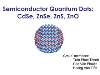
Semiconductor Quantum Dots:
    CdSe, ZnSe, ZnS, ZnO


                  Group’ members:
                        Trần Phúc Thành
                        Cao Văn Phước
                        Hoàng Văn Tiến
Outline

• Introduction
   – What is semiconductor quantum dots
   – Why quantum dots
   – Properties
• Synthesis
• Applications, challenges, and potentials
• Conclusions
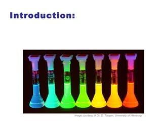
Introduction:


            Image courtesy of Dr. D. Talapin, University of Hamburg
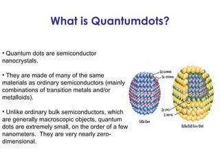
What is Quantumdots?

• Quantum dots are semiconductor
nanocrystals.

• They are made of many of the same
materials as ordinary semiconductors (mainly
combinations of transition metals and/or
metalloids).

• Unlike ordinary bulk semiconductors, which
are generally macroscopic objects, quantum
dots are extremely small, on the order of a few
nanometers. They are very nearly zero-
dimensional.
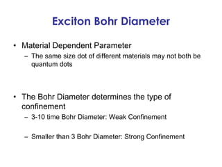
Exciton Bohr Diameter

• Material Dependent Parameter
  – The same size dot of different materials may not both be
    quantum dots


• The Bohr Diameter determines the type of
  confinement
  – 3-10 time Bohr Diameter: Weak Confinement

  – Smaller than 3 Bohr Diameter: Strong Confinement
Experimental Observation of
            Confinement
• Just imaging a small dot is not enough to say it is
  confined
• Optical data allows insight into confinement
   – Optical Absorption
   – Raman Vibration Spectroscopy
   – Photoluminescence Spectroscopy
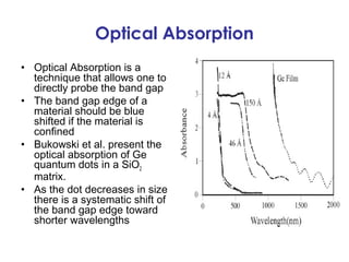
Optical Absorption
• Optical Absorption is a
  technique that allows one to
  directly probe the band gap
• The band gap edge of a
  material should be blue
  shifted if the material is
  confined
• Bukowski et al. present the
  optical absorption of Ge
  quantum dots in a SiO2
  matrix.
• As the dot decreases in size
  there is a systematic shift of
  the band gap edge toward
  shorter wavelengths
Raman Vibrational Spectroscopy
• Raman vibrational
  spectroscopy probes the
  vibrational modes of a
  sample using a laser
• As the nanocrystal becomes
  more confined the peak will
  broaden and shrink
• Here we see a peak shift
  toward the laser line
• Various Ge dots of different
  sizes on an Alumina film
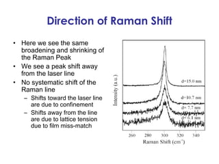
Direction of Raman Shift
• Here we see the same
  broadening and shrinking of
  the Raman Peak
• We see a peak shift away
  from the laser line
• No systematic shift of the
  Raman line
   – Shifts toward the laser line
     are due to confinement
   – Shifts away from the line
     are due to lattice tension
     due to film miss-match
Photoluminescence Spectroscopy
• Photoluminescence
  spectroscopy is a
  technique to probe the
  quantum levels of
  quantum dots
• Here we see dots of
  various size in a
  quantum well
   – (a) is quantum well
     spectrum
   – (d) is smallest particles
     80 nm
Properties of Quantum Dots Compared to
           Organic Fluorphores?
           High quantum yield; often 20 times brighter
            Narrower and more symmetric emission spectra
            100-1000 times more stable to photobleaching
            High resistance to photo-/chemical degradation
           Tunable wave length range 400-4000 nm


                           CdSe

                                                                                           CdTe


http://www.sussex.ac.uk/Users/kaf18/QDSpectra.jpg
                                                    J. Am. Chem. Soc. 2001, 123, 183-184
Why
Excitation in a Semiconductor
                The excitation of an electron from the valance band
                to the conduction band creates an electron hole pair
                                       E

                                                                       ECB           hυ E
                                                                                       =g


      −
       ( ) + )
    h↔ BhV
    υ e C+ ( B
Creation of an electron hole pair
where hν is the photon energy                                          EVB


                semiconductor                                           Band Gap
     optical
     detector                                                           (energy barrier)
                                    E=hυ


                                           exciton: bound electron and hole pair
                                           usually associated with an electron trapped in a
                                           localized state in the band gap
Recombination of Electron Hole Pairs
                           Recombination can happen two ways:

                                           radiative and non-radiative
                                                                    E

                                                                                                        ECB
                                    recombination processes


                                                                                                       EVB

E
                                                                           band-to-band     recom bination
                                                                           recom bination   atinterband trap states
                                                          ECB                               (e.g. dopants, impurities)
    E = hυ


                                                                radiative recombination → photon
                                                          EVB
                                                                non-radiative recombination → phonon (lattice
                                                                vibrations)
                                                                        −
                                                                           ) + ) υ
             ra d ia tive              n o n -ra d ia tive
             re co m b in a tio n      re c o m b in a tio n            e C+ ( B h
                                                                         ( BhV→
Effective Mass Model

                Developed in 1985 By Louis Brus

                Relates the band gap to particle size of a spherical
                quantum dot


Band gap of spherical particles
The average particle size in suspension can be obtained from the absorption
onset using the effective mass model where the band gap E* (in eV) can be
approximated by:
                          −
        π   .e 1 
       h2 1 1 1 03 1 1
         2
               8 .42e     
                          1
    E + + 
    =         − −     + 
    *b
     u
     l
     k
     E 2 m hπ h 2 ε 0 h
            m ε ( 0m m
                     )
             m ε 4 2e m
     g
          0
       2 e
        e
        r     0
           m 04 r  π
                    ε m0  

Egbulk - bulk band gap (eV),               h - Plank’s constant (h=6.626x10⁻³⁴ J·s)
r - particle radius                        e - charge on the electron (1.602x10⁻¹⁹ C)
me - electron effective mass               ε - relative permittivity
mh - hole effective mass                   ε0 - permittivity of free space (8.854 x10⁻¹⁴ F cm-1)
m0 - free electron mass (9.110x10⁻³¹ kg)
                                                              Brus, L. E. J. Phys. Chem. 1986, 90, 2555
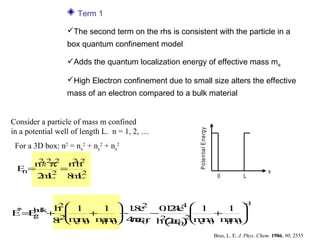
Term 1

                  The second term on the rhs is consistent with the particle in a
                  box quantum confinement model

                  Adds the quantum localization energy of effective mass me

                  High Electron confinement due to small size alters the effective
                  mass of an electron compared to a bulk material


Consider a particle of mass m confined


                                                        P oten tia l E nergy
in a potential well of length L. n = 1, 2, …
 For a 3D box: n2 = nx2 + ny2 + nz2
     2
        π
    n h2 2 n h
            22
 E=
  n     2
          =                                                                                            x
    2 L 8 L
     m      m2                                                                  0           L


                                              −
         h 1    1  1e
                      . 2 0 2e  1         1 
          2                                    1
                       8    . 44
                             1
E = g lk+ 2
 *
   Eu
    b
               +   −     −             +   
          r m 0 m 0 4 ε 0 h ( ε 0 2 e 0 m 0
         8  em  hm   πεr 2 2ε ) m     m   hm
                                                                               Brus, L. E. J. Phys. Chem. 1986, 90, 2555
Term 2

               The Coulombic attraction between electrons and holes lowers
              the energy

              Accounts for the interaction of a positive hole me+ and a negative
              electron me-

                Electrostatic force (N) between two charges (Coulomb’s Law):
                              qq
                       F= 1 2 2                   Work, w = ∫F·dr
                               εε
                            4π 0r
Consider an electron (q=e-) and a hole (q=e+)
The decrease in energy on bringing a positive                    r
charge to distance r from a negative charge is:
                                     2        2
                                    e        e
                             ∆ =∫
                              E         d=
                                         r −
                                  4 ε0
                                   πε r2    4 ε0
                                             πε r
                                                 −
            h 1    1  1e
                         . 2 0 2e  1         1 
             2                                    1
                          8    . 44
                                1
   E = g l + 2
    *
      Euk
       b
                  +   −     −             +   
             r m 0 m 0 4 ε 0 h ( ε 0 2 e 0 m 0
            8  em  hm   πεr 2 2ε ) m     m   hm

                                                         Brus, L. E. J. Phys. Chem. 1986, 90, 2555
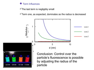
Term Influences

The last term is negligibly small

Term one, as expected, dominates as the radius is decreased


     Energy (eV )
      Modulus       1                                             term 1

                                                                  term 2

                                                                  term 3

                    0
                        0              5            10
                                     d (nm)

                            Conclusion: Control over the
                            particle’s fluorescence is possible
                            by adjusting the radius of the
                            particle
Quantum Confinement of ZnO
                         ZnO has small effective masses  quantum effects can be
                         observed for relatively large particle sizes

                         Confinement effects are observed for particle sizes <~8 nm


                                                          ZnO               CdSe
                                        ZnO               λbulk = 365 nm    λbulk = 709 nm
                                                          ε = 8.66          ε = 10.6
   Eg (eV)


                4
                                                          me* = 0.24        me* = 0.13
                                                          mh* = 0.59        mh* = 0.45

                 3
               400
λ onset (nm)


               350


               300


               250
                     0        5               10
                             d (nm)
Fabrication Methods

• Goal: to engineer potential energy barriers to confine
  electrons in 3 dimensions


• 3 primary methods
   – Lithography
   – Colloidal chemistry
   – Epitaxy
2. Fabrication of Quantum Dots


      How to Make Quantum Dots

• There are three main ways to confine excitons in
  semiconductors:
   – Lithography
   – Colloidal synthesis
   – Epitaxy:
             » Patterned Growth
             » Self-Organized Growth


21
2. Fabrication of Quantum Dots


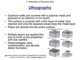
                                 Lithography
• Quantum wells are covered with a polymer mask and
  exposed to an electron or ion beam.
• The surface is covered with a thin layer of metal, then
  cleaned and only the exposed areas keep the metal layer.
• Pillars are etched into the entire surface.

• Multiple layers are applied this
  way to build up the properties
  and size wanted.
• Disadvantages: slow,
  contamination, low density,
  defect formation.

Resulting quantum dot etched in GaAs/AlGaAs superlattice.
22
    L. Jacak, P. Hawrylak, A. Wojs. Quantum dots fig. 2.2.
2. Fabrication of Quantum Dots


              Colloidal Synthesis

• Immersion of semiconductor microcrystals in glass
  dielectric matrices.
• Taking a silicate glass with 1% semiconducting phase
  (CdS, CuCl, CdSe, or CuBr).
• Heating for several hours at high temperature.
⇒ Formation of microcrystals of nearly equal size.


• Typically group II-VI materials (e.g. CdS, CdSe)
• Size variations (“size dispersion”).


23
2. Fabrication of Quantum Dots


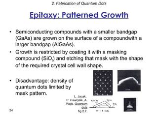
         Epitaxy: Patterned Growth

• Semiconducting compounds with a smaller bandgap
  (GaAs) are grown on the surface of a compoundwith a
  larger bandgap (AlGaAs).
• Growth is restricted by coating it with a masking
  compound (SiO2) and etching that mask with the shape
  of the required crystal cell wall shape.

• Disadvantage: density of
  quantum dots limited by
  mask pattern.            L. Jacak,
                          P. Hawrylak, A.
                          Wojs. Quantum
                                     dots
24                                fig 2.7.
2. Fabrication of Quantum Dots


     Epitaxy: Self-Organized Growth
• Uses a large difference in the lattice constants of the
  substrate and the crystallizing material.
• When the crystallized layer is thicker than the critical
  thickness, there is a strong strain on the layers.
• The breakdown results in randomly distributed islets of
  regular shape and size.

• Disadvantages: size and
  shape fluctuations, ordering.

        Schematic drawing of lens-shaped self-
                      organized quantum dot.
                                    L. Jacak,
                                P. Hawrylak,
                            A. Wojs. Quantum
                                          dots
25                                     fig 8.1.
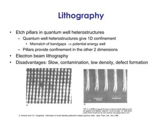
Lithography
•   Etch pillars in quantum well heterostructures
     – Quantum well heterostructures give 1D confinement
             • Mismatch of bandgaps ⇒ potential energy well
     – Pillars provide confinement in the other 2 dimensions
•   Electron beam lithography
•   Disadvantages: Slow, contamination, low density, defect formation


     A. Scherer and H.G. Craighead. Fabrication of small laterally patterned multiple quantum wells. Appl. Phys. Lett., Nov 1986.
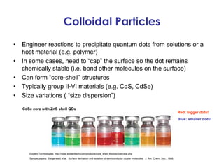
Colloidal Particles
•   Engineer reactions to precipitate quantum dots from solutions or a
    host material (e.g. polymer)
•   In some cases, need to “cap” the surface so the dot remains
    chemically stable (i.e. bond other molecules on the surface)
•   Can form “core-shell” structures
•   Typically group II-VI materials (e.g. CdS, CdSe)
•   Size variations ( “size dispersion”)

    CdSe core with ZnS shell QDs
                                                                                                                                         Red: bigger dots!
                                                                                                                                         Blue: smaller dots!


       Evident Technologies: http://www.evidenttech.com/products/core_shell_evidots/overview.php
       Sample papers: Steigerwald et al. Surface derivation and isolation of semiconductor cluster molecules. J. Am. Chem. Soc., 1988.
Epitaxy: Patterned Growth
•   Growth on patterned
    substrates
    – Grow QDs in pyramid-shaped
      recesses
    – Recesses formed by selective
      ion etching
    – Disadvantage: density of QDs
      limited by mask pattern


                                     T. Fukui et al. GaAs tetrahedral quantum dot structures fabricated using selective area metal
                                     organic chemical vapor deposition. Appl. Phys. Lett. May, 1991
Epitaxy: Self-Organized Growth
•   Self-organized QDs through epitaxial growth strains
     – Stranski-Krastanov growth mode (use MBE, MOCVD)
               • Islands formed on wetting layer due to lattice mismatch (size ~10s nm)
     – Disadvantage: size and shape fluctuations, ordering
     – Control island initiation
               • Induce local strain, grow on dislocation, vary growth conditions, combine
                 with patterning
                                                                                                                   AFM images of islands
                                                                                                                   epitaxiall grown on GaAs
                                                                                                                   substrate.
                                                                                                               (a) InAs islands randomly
                                                                                                                   nucleate.
                                                                                                               (b) Random distribution of
                                                                                                                   InxGa1­xAs ring­shaped
                                                                                                                   islands.
                                                                                                               (c) A 2D lattice of InAs islands on
                                                                                                                   a GaAs substrate.


    P. Petroff, A. Lorke, and A. Imamoglu. Epitaxially self-assembled quantum dots. Physics Today, May 2001.
APPLICATIONS
Quantum computing


A quantum computer is a computer design which uses the principles of quantum physi
to increase the computational power beyond what is attainable by a traditional compute
The tiny seven-atom quantum dot created by scientists (left), with a close-up of
 that dot forming an atomic-scale transistor (right)


 essential for the creation of semiconductor­based quantum computers,
which could be faster and provide more memory than conventional
technology.
Rules:

-By applying small voltages to the leads, the flow of electrons through the
quantum dot can be controlled and thereby precise measurements of the
spin and other properties therein can be made.

-With several entangled quantum dots, or qubits , plus a way of performing
operations, quantum calculations and the computers that would perform
them might be possible.

 Bits :a bit can be defined as a variable or computed quantity that can have
 only two possible values : 0/1 or on/off…
 Qubits: -quantum mechanics allows the qubit to be in a superposition of
 both states at the same time, a property which is fundamental to quantum
 computing.
            - a qubit can be 0, 1, or a superposition of both.
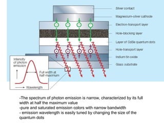
Quantum-dot light-emmiting
     diodes ( QDLED)
-The spectrum of photon emission is narrow, characterized by its full
width at half the maximum value
-pure and saturated emission colors with narrow bandwidth
- emission wavelength is easily tuned by changing the size of the
quantum dots
• Advantages :
   – Low power consumption
   – Ranger and accuracy color
   – Brightness: 50~100 times brighter than CRT and LCD
     displays ~40,000 cd/m2
   – QLED screens are said to be twice as power efficient as
     OLED screens, and offer 30 to 40% improved brightness.
• Disadvantages :
   – Less saturated blue
   – expensive
Quantum dot solar cell

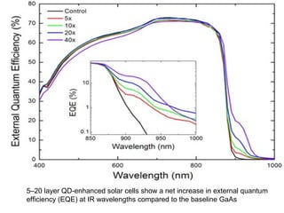
• Quantum dots have bandgaps that are tunable across a
  wide range of energy levels by changing the quantum
  dot size.
5–20 layer QD-enhanced solar cells show a net increase in external quantum
efficiency (EQE) at IR wavelengths compared to the baseline GaAs
How Can Quantum Dots Improve
            the Efficiency?
• Quantum dots can generate multiple exciton (electron-
  hole pairs) after collision with one photon.


39
                                                          39
Spin­cast quantum dot solar cell       roll-to-roll solar cell fabrication.


• Results:
   – -conversion efficiencies up to a record-breaking 7 percent efficiency.
   – The efficiency of solar cells could be increased to more than 60%
     from the current limit of just 30%...
Another applications

•   Photodetector devices
•   Quantum dots laser
•   Colloidal quantum dots
•   Uses in biology:use of QDs as passive labels in sensor
    applications, gene technology, pathogen and toxin
    detection…
Challenges and potentials
•   Potentials :
     – The composition and very small size of quantum dots (5–8
       nm) gives them unique and very stable fluorescent optical
       properties that are readily tunable by changing their physical
       composition or size.
     – Their broad absorption spectra but very narrow emission
       spectra allows multiplexing of many quantum dots of
       different colors in the same sample.
     – quantum dots can be made from many different elements,
       and come in many different shapes and sizes,
•   Challenges :
     – Hard to control the side of dots.
     – Cytotoxic Effect
     – Environmental toxicity:
         • Phytotoxicity
         • Marine toxicity
conclusion
•   Quantum dot are the new and inovative perspective on the
    traditional semiconductor
•   Quantum dot can be synthesized to be essentially any size,
    and therefore produce essentially any wavelength of light
•   Application of Quantum Dots that they are useful in many
    conditions due to their physiochemical properties Quantum
    Dots may used in different fields by altering their surface
    property, internal structures, preparation techniques, coating
    material etc.
•   The future looks bright and exciting on all the possible
    applications of quantum dots
references
 1, http://en.wikipedia.org/wiki/Quantum_dot
2. http://nature.com
3. http://google.com
4. Y. Masumoto and T. Takagahara. Semiconductor Quantum Dots: Physics,
   Spectroscopy, and Applications. New York: Springer-Verlag, 2002.
5. Synthesis and Applications of Nanoparticles and
   Quantum Dots-Richard D. Tilley
6. http://www.nanowerk.com
7. http://led-professional.com
8. http://quantumdotstech.com/
9. http://youtube.com
………
quantum dots