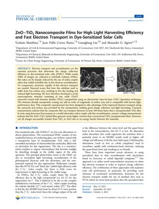
This document describes a study on developing a novel nanocomposite structure for dye-sensitized solar cells (DSSCs) consisting of zinc oxide (ZnO) nanorods coated with titanium dioxide (TiO2) nanoparticles. The ZnO nanorods provide fast electron transport while the TiO2 nanoparticles add high surface area for dye adsorption. Transient measurements show the composite film can transport electrons over 100 times faster than TiO2 nanoparticle films alone. When tested with an alternative redox couple that has fast recombination (ferrocene/ferrocenium), the ZnO-TiO2 films generate higher currents than TiO2 films, demonstrating their ability to better collect injected electrons. However, not all charges successfully transfer from TiO2 to Z
Synthesis and characterization of nano tio2 via different methodshena78
Titanium Dioxide nanoparticles are the ultra fine particles Particles of titanium dioxide (TiO2) have the diameters less than 100 nm. It is believed to be one of the three most produced nanomaterials , along with silicon dioxide nanoparticles and zinc oxide nanoparticles.
Synthesis, Characterization of ZnS nanoparticles by Coprecipitation method us...IOSR Journals
ZnS nanoparticles are prepared by coprecipitation method using various capping agents like PVP (polyvinylpyrrolidone), PVA (polyvinylalcohol) and PEG-4000 (polyethyleneglycol). These are characterized by UV-Visible spectra, X-ray diffraction (XRD) studies, Fourier Transform Infra-red spectra (FTIR) and Transmission electron microscopy (TEM). UV-Visible absorption spectra are used to find the optical band gap and the values obtained have been found to be in the range of 3.80-4.00eV. The particle size of nanoparticles calculated from XRD pattern has been in the range of 2-4 nm. It is also observed that the particle size of nanoparticle is affected by the nature of capping agent. Photo catalytic degradation of xylenol orange (XO) by the nanoparticles shows that these act as photo catalysts under sunlight irradiation. The XO dye was degraded more than 87.24, 83.42 and 73.05% in the presence of PEG-4000, PVA and PVP capped ZnS nanoparticles in 120, 150 and 180 min. respectively. The kinetics of catalyzed by synthesized ZnS nanoparticles with XO dye follows pseudo-first order kinetics with reasonable apparent rate constants.
With the increasing researches in the field of nanotechnology, various nanoparticles have become a source of interest among the nano technologists because of their great properties, like the optical properties of Cadmium Sulfide Nanoparticles are amazing and also easy to synthesize, but to make sure its quality it is equally essential to make out characterize it, this file will do the same in a lucid way!!
Synthesis and charaterization of la1 x srxmno3 perovskite nanoparticlesMai Trần
In recent times perovskite materials are extensively studied and have attracted much attention because they exhibit interesting the properties, showing potential applications in commercial, technical and biomedical. In Vietnam, perovskite materials be of interest research and applications are strong but with major research direction is to go deep into the electrical properties and the magnetic properties. The Lanthanum Strontium manganite is a perovskite-based crystal-structured ceramic material with the formula of La1-xSrxMnO3, where x describes the doping ratio. It has attracted much attention due to its good magnetic, electrical, and catalytic properties and is becoming an attractive possibility material in several biomedical applications, particularly with nano-size. In industry, this material is commonly used in as a cathode material in commercially produced solid oxide fuel cells. In this thesis, we present the Perovskite nanoparticles La1-xSrxMnO3 were successfully synthesized of the nanosize La1-xSrxMnO3 at x = 0; 0.1; 0.2; 0.3 and 0.4 which prepared by a modified sol-gel method. Structure and magnetic properties of them were systematically investigated in dependence on doped Sr ratio x. The structure was investigated by XRD and show slightly changed but magnetic properties varied strongly with changing the doping ratio x. Magnetic properties of samples were studied by Vibrating Sample Mode of Physical Properties Measurement System show at the room temperature, the samples show superparamagnetic properties with high saturated magnetization MS of 57 emu/g which strongly dependents on the doped Sr ratio x.
Synthesis and characterization of ZnO nanoparticles via aqueous solution, sol...iosrjce
ZnO nanoparticles were synthesized by aqueous solution method, sol-gel method and hydrothermal
method.The synthesized particles were characterized by XRD ,SEM ,EDX and UV .The X-ray diffraction studies
reveals that the synthesized ZnO nanoparticles have wurtzite structure and the particle size varies from 13 to 18
nm. Scanning Electron Microscopic investigation reveals that the surface morphology of ZnO nanoparticle is
spherical in hydrothermal process and varies to flower like arrangement in aqueous solution and sol-gel
process. The UV-Visible spectrum of the nanoparticles shows a blue shift compared to that of the bulk sample.
This is a power point presentation of project work on preparing Zinc oxide thin films by using SILAR technique and CBD technique and studying its characteristics.
IOSR Journal of Applied Physics (IOSR-JAP) is an open access international journal that provides rapid publication (within a month) of articles in all areas of physics and its applications. The journal welcomes publications of high quality papers on theoretical developments and practical applications in applied physics. Original research papers, state-of-the-art reviews, and high quality technical notes are invited for publications.
Characterization of different dopants in TiO2 Structure by Pulsed Laser Dep...sarmad
Characterization of different dopants in TiO2 Structure by Pulsed Laser Deposition
A thesis submitted By: Khaled Z.Yahya
Supervised by: Prof.Dr. Adawiya J.Haider Prof.Dr. Raad M.S.Al-Haddad
Nanoparticles are particles between 1 and 100 nanometres in size with a surrounding interfacial layer. The interfacial layer is an integral part of nanoscale matter, fundamentally affecting all of its properties. The interfacial layer typically consists of ions, inorganic and organic molecules.
Vapor Deposition of Semiconducting Phosphorus Allotropes into TiO2 Nanotube A...Pawan Kumar
Recent evidence of exponential environmental degradation will demand a drastic shift in research and development toward
exploiting alternative energy resources such as solar energy. Here, we
report the successful low-cost and easily accessible synthesis of hybrid
semiconductor@TiO2 nanotube photocatalysts. In order to realize its
maximum potential in harvesting photons in the visible-light range, TiO2
nanotubes have been loaded with earth-abundant, low-band-gap fibrous
red and black phosphorus (P). Scanning electron microscopy− and
scanning transmission electron microscopy−energy-dispersive X-ray
spectroscopy, X-ray diffraction, Raman spectroscopy, X-ray photoelectron microscopy, and UV−vis measurements have been performed,
substantiating the deposition of fibrous red and black P on top and
inside the cavities of 100-μm-long electrochemically fabricated nanotubes. The nanotubular morphology of titania and a vapor-transport technique are utilized to form heterojunctions of P and
TiO2. Compared to pristine anatase 3.2 eV TiO2 nanotubes, the creation of heterojunctions in the hybrid material resulted in
1.5−2.1 eV photoelectrocatalysts. An enhanced photoelectrochemical water-splitting performance under visible light compared
with the individual components resulted for the P@TiO2 hybrids. This feature is due to synergistically improved charge
separation in the heterojunction and more effective visible-light absorption. The electronic band structure and charge-carrier
dynamics are investigated in detail using ultraviolet photoelectron spectroscopy and Kelvin probe force microscopy to elucidate
the charge-separation mechanism. A Fermi-level alignment in P@TiO2 heterojunctions leads to a more reductive flat-band
potential and a deeper valence band compared to pristine P and thus facilitates a better water-splitting performance. Our results
demonstrate effective conversion efficiencies for the nanostructured hybrids, which may enable future applications in
optoelectronic applications such as photodetectors, photovoltaics, photoelectrochemical catalysts, and sensors.
Vapor growth of binary and ternary phosphorusbased semiconductors into TiO2 n...Pawan Kumar
We report successful synthesis of low band gap inorganic polyphosphide and TiO2 heterostructures with
the aid of short-way transport reactions. Binary and ternary polyphosphides (NaP7, SnIP, and (CuI)3P12)
were successfully reacted and deposited into electrochemically fabricated TiO2 nanotubes. Employing
vapor phase reaction deposition, the cavities of 100 mm long TiO2 nanotubes were infiltrated;
approximately 50% of the nanotube arrays were estimated to be infiltrated in the case of NaP7. Intensive
characterization of the hybrid materials with techniques including SEM, FIB, HR-TEM, Raman
spectroscopy, XRD, and XPS proved the successful vapor phase deposition and synthesis of the
substances on and inside the nanotubes. The polyphosphide@TiO2 hybrids exhibited superior water
splitting performance compared to pristine materials and were found to be more active at higher
wavelengths. SnIP@TiO2 emerged to be the most active among the polyphosphide@TiO2 materials. The
improved photocatalytic performance might be due to Fermi level re-alignment and a lower charge
transfer resistance which facilitated better charge separation from inorganic phosphides to TiO2.
Vapor Deposition of Semiconducting Phosphorus Allotropes into TiO2 Nanotube A...Pawan Kumar
Recent evidence of exponential environmental degradation will demand a drastic shift in research and development toward exploiting alternative energy resources such as solar energy. Here, we report the successful low-cost and easily accessible synthesis of hybrid semiconductor@TiO2 nanotube photocatalysts. In order to realize its maximum potential in harvesting photons in the visible-light range, TiO2 nanotubes have been loaded with earth-abundant, low-band-gap fibrous red and black phosphorus (P). Scanning electron microscopy– and scanning transmission electron microscopy–energy-dispersive X-ray spectroscopy, X-ray diffraction, Raman spectroscopy, X-ray photoelectron microscopy, and UV–vis measurements have been performed, substantiating the deposition of fibrous red and black P on top and inside the cavities of 100-μm-long electrochemically fabricated nanotubes. The nanotubular …
Natural Dye-Sensitized Solar Cells (NDSSCs) From Opuntia Prickly Pear Dye Usi...IJERA Editor
Natural dye-sensitized solar cells (NDSSCs) have gained considerable attention in the field of solar energy due to their simple fabrication, good efficiency, and low production cost. Natural dyes are environmentally and economically superior to ruthenium-based dyes because they are nontoxic and cheap. However, the conversion efficiency of dye-sensitized solar cells based on natural dyes is low. One way to improve the DSSC performance is to enhance the absorptivity of extracted natural dyes. We investigated the influence of various factors in the extraction process, such as utilization of different extraction approaches, the acidity of extraction solvent, and different compounds of solvents on the optical absorption spectra. It was found that we could considerably enhance the optical absorptivity of dye and consequently the performance of DSSC by choosing a proper mixture of ethanol, methanol and water. In this study, a photo electrode using ZnO doped TiO2 nanoparticles was prepared by sol-gel method. In this paper we investigate the optical absorption, functional group, surface morphology and elementary composition of pure TiO2, ZnO doped TiO2 nanoparticles and opuntia prickly pear dye extract by using UV-Visible, PL-Studies, FT-IR, FE-SEM and EDS analysis. Finally photocurrent-voltaic characterization of nanocrystaline natural dye solar cell using I-V studies. It was found that the levels of short-circuit current (Jsc), open-circuit voltage (Voc), fill factor (FF) and overall conversion efficiency (η).
Vapor growth of binary and ternary phosphorus-based semiconductors into TiO 2...Pawan Kumar
We report successful synthesis of low band gap inorganic polyphosphide and TiO2 heterostructures with the aid of short-way transport reactions. Binary and ternary polyphosphides (NaP7, SnIP, and (CuI)3P12) were successfully reacted and deposited into electrochemically fabricated TiO2 nanotubes. Employing vapor phase reaction deposition, the cavities of 100 μm long TiO2 nanotubes were infiltrated; approximately 50% of the nanotube arrays were estimated to be infiltrated in the case of NaP7. Intensive characterization of the hybrid materials with techniques including SEM, FIB, HR-TEM, Raman spectroscopy, XRD, and XPS proved the successful vapor phase deposition and synthesis of the substances on and inside the nanotubes. The polyphosphide@TiO2 hybrids exhibited superior water splitting performance compared to pristine materials and were found to be more active at higher wavelengths. SnIP …
This paper presents a Dye sensitized solar cell (DYSSC), which is called as future generation solar cell. It is a
new class of green photovoltaic cell based on photosynthesis principle in nature. DYSSCs are fabricated using
two different natural dyes as sensitizers, which extracted from the materials existing in nature and our life, such
as flowers, leaves, fruits, traditional Chinese medicines, and beverages. The use of sensitizers having a broad
absorption band in conjunction with oxide films of nanocrystalline morphology permits to harvest a large
fraction of sunlight. There are good prospects to produce these cells at lower cost and much better efficiency
than conventional semiconductor devices by introducing various chemical and natural dyes. DYSSC are
implemented with simple and new technique to overcome the energy crisis and excess cost of semiconductor
solar cells.
Impact of CuS counter electrode calcination temperature on quantum dot sensit...TELKOMNIKA JOURNAL
In place of the commercial Pt electrode used in quantum sensitized solar cells, the low-cost CuS cathode is created using electrophoresis. High resolution scanning electron microscopy and X-ray diffraction were used to analyze the structure and morphology of structural cubic samples with diameters ranging from 40 nm to 200 nm. The conversion efficiency of solar cells is significantly impacted by the calcination temperatures of cathodes at 100 °C, 120 °C, 150 °C, and 180 °C under vacuum. The fluorine doped tin oxide (FTO)/CuS cathode electrode reached a maximum efficiency of 3.89% when it was calcined at 120 °C. Compared to other temperature combinations, CuS nanoparticles crystallize at 120 °C, which lowers resistance while increasing electron lifetime.
In place of the commercial Pt electrode used in quantum sensitized solar cells, the low-cost CuS cathode is created using electrophoresis. High resolution scanning electron microscopy and X-ray diffraction were used to analyze the structure and morphology of structural cubic samples with diameters ranging from 40 nm to 200 nm. The conversion efficiency of solar cells is significantly impacted by the calcination temperatures of cathodes at 100 °C, 120 °C, 150 °C, and 180 °C under vacuum. The fluorine doped tin oxide (FTO)/CuS cathode electrode reached a maximum efficiency of 3.89% when it was calcined at 120 °C. Compared to other temperature combinations, CuS nanoparticles crystallize at 120 °C, which lowers resistance while increasing electron lifetime.
Builder.ai Founder Sachin Dev Duggal's Strategic Approach to Create an Innova...Ramesh Iyer
In today's fast-changing business world, Companies that adapt and embrace new ideas often need help to keep up with the competition. However, fostering a culture of innovation takes much work. It takes vision, leadership and willingness to take risks in the right proportion. Sachin Dev Duggal, co-founder of Builder.ai, has perfected the art of this balance, creating a company culture where creativity and growth are nurtured at each stage.
Dev Dives: Train smarter, not harder – active learning and UiPath LLMs for do...UiPathCommunity
💥 Speed, accuracy, and scaling – discover the superpowers of GenAI in action with UiPath Document Understanding and Communications Mining™:
See how to accelerate model training and optimize model performance with active learning
Learn about the latest enhancements to out-of-the-box document processing – with little to no training required
Get an exclusive demo of the new family of UiPath LLMs – GenAI models specialized for processing different types of documents and messages
This is a hands-on session specifically designed for automation developers and AI enthusiasts seeking to enhance their knowledge in leveraging the latest intelligent document processing capabilities offered by UiPath.
Speakers:
👨🏫 Andras Palfi, Senior Product Manager, UiPath
👩🏫 Lenka Dulovicova, Product Program Manager, UiPath
Software Delivery At the Speed of AI: Inflectra Invests In AI-Powered QualityInflectra
In this insightful webinar, Inflectra explores how artificial intelligence (AI) is transforming software development and testing. Discover how AI-powered tools are revolutionizing every stage of the software development lifecycle (SDLC), from design and prototyping to testing, deployment, and monitoring.
Learn about:
• The Future of Testing: How AI is shifting testing towards verification, analysis, and higher-level skills, while reducing repetitive tasks.
• Test Automation: How AI-powered test case generation, optimization, and self-healing tests are making testing more efficient and effective.
• Visual Testing: Explore the emerging capabilities of AI in visual testing and how it's set to revolutionize UI verification.
• Inflectra's AI Solutions: See demonstrations of Inflectra's cutting-edge AI tools like the ChatGPT plugin and Azure Open AI platform, designed to streamline your testing process.
Whether you're a developer, tester, or QA professional, this webinar will give you valuable insights into how AI is shaping the future of software delivery.
Neuro-symbolic is not enough, we need neuro-*semantic*Frank van Harmelen
Neuro-symbolic (NeSy) AI is on the rise. However, simply machine learning on just any symbolic structure is not sufficient to really harvest the gains of NeSy. These will only be gained when the symbolic structures have an actual semantics. I give an operational definition of semantics as “predictable inference”.
All of this illustrated with link prediction over knowledge graphs, but the argument is general.
Transcript: Selling digital books in 2024: Insights from industry leaders - T...BookNet Canada
The publishing industry has been selling digital audiobooks and ebooks for over a decade and has found its groove. What’s changed? What has stayed the same? Where do we go from here? Join a group of leading sales peers from across the industry for a conversation about the lessons learned since the popularization of digital books, best practices, digital book supply chain management, and more.
Link to video recording: https://bnctechforum.ca/sessions/selling-digital-books-in-2024-insights-from-industry-leaders/
Presented by BookNet Canada on May 28, 2024, with support from the Department of Canadian Heritage.
Kubernetes & AI - Beauty and the Beast !?! @KCD Istanbul 2024Tobias Schneck
As AI technology is pushing into IT I was wondering myself, as an “infrastructure container kubernetes guy”, how get this fancy AI technology get managed from an infrastructure operational view? Is it possible to apply our lovely cloud native principals as well? What benefit’s both technologies could bring to each other?
Let me take this questions and provide you a short journey through existing deployment models and use cases for AI software. On practical examples, we discuss what cloud/on-premise strategy we may need for applying it to our own infrastructure to get it to work from an enterprise perspective. I want to give an overview about infrastructure requirements and technologies, what could be beneficial or limiting your AI use cases in an enterprise environment. An interactive Demo will give you some insides, what approaches I got already working for real.
Generating a custom Ruby SDK for your web service or Rails API using Smithyg2nightmarescribd
Have you ever wanted a Ruby client API to communicate with your web service? Smithy is a protocol-agnostic language for defining services and SDKs. Smithy Ruby is an implementation of Smithy that generates a Ruby SDK using a Smithy model. In this talk, we will explore Smithy and Smithy Ruby to learn how to generate custom feature-rich SDKs that can communicate with any web service, such as a Rails JSON API.
The Art of the Pitch: WordPress Relationships and SalesLaura Byrne
Clients don’t know what they don’t know. What web solutions are right for them? How does WordPress come into the picture? How do you make sure you understand scope and timeline? What do you do if sometime changes?
All these questions and more will be explored as we talk about matching clients’ needs with what your agency offers without pulling teeth or pulling your hair out. Practical tips, and strategies for successful relationship building that leads to closing the deal.
UiPath Test Automation using UiPath Test Suite series, part 4DianaGray10
Welcome to UiPath Test Automation using UiPath Test Suite series part 4. In this session, we will cover Test Manager overview along with SAP heatmap.
The UiPath Test Manager overview with SAP heatmap webinar offers a concise yet comprehensive exploration of the role of a Test Manager within SAP environments, coupled with the utilization of heatmaps for effective testing strategies.
Participants will gain insights into the responsibilities, challenges, and best practices associated with test management in SAP projects. Additionally, the webinar delves into the significance of heatmaps as a visual aid for identifying testing priorities, areas of risk, and resource allocation within SAP landscapes. Through this session, attendees can expect to enhance their understanding of test management principles while learning practical approaches to optimize testing processes in SAP environments using heatmap visualization techniques
What will you get from this session?
1. Insights into SAP testing best practices
2. Heatmap utilization for testing
3. Optimization of testing processes
4. Demo
Topics covered:
Execution from the test manager
Orchestrator execution result
Defect reporting
SAP heatmap example with demo
Speaker:
Deepak Rai, Automation Practice Lead, Boundaryless Group and UiPath MVP
2. mentioned above, which tend to be large and difficult to
synthesize.
Electron transport in DSSCs is slow, due to trapping of the
electrons in the grain boundaries and the relatively long and
tortuous path of the electron to the fluorine-doped tin oxide
(FTO).6,7
In a 10 μm thick film an electron visits about 106
nanoparticles on average before reaching the FTO surface.8
The resulting slow transport is adequate in the presence of
iodide/triiodide, since its recombination kinetics are slow, but
inadequate when using an alternative redox couple with faster
recombination.
Fast electron transport can be achieved by developing 1-D
nanostructures like nanotubes, nanorods, and nanowires of
metal oxides. ZnO is a highly favorable material for application
in DSSCs, since it can be grown in monocrystalline nanorods
using facile methods, its electron mobility is high,9
and its band
edge energies are very close to those of TiO2.10
ZnO is the
metal oxide with the second highest efficiency achieved in
DSSCs.11−13
ZnO nanorods can be synthesized on various
substrates in situ by procedures such as chemical bath
deposition,14,15
electrodeposition,16−18
and chemical vapor
deposition,19,20
and in DSSCs they can transport electrons
more than an order of magnitude faster than a TiO2
nanoparticulate film.21
However, the main disadvantage of
nanorods is their lower surface area than a nanoparticle film for
adsorption of light-harvesting molecules. In addition, dyes
partially dissolve the ZnO, forming a deleterious Zn2+
−dye
surface complex.22
Previous efforts to circumvent these shortcomings have
tended to either boost the surface area of the ZnO, e.g. by
adding ZnO nanoparticles23
or secondary nanorods,24
or to
improve dye performance via, for example, a protective
conformal TiO2 encapsulation of ZnO.25
To create a structure
with both fast electron transport and high surface area, we
developed a hybrid photoanode consisting of ZnO nanorods
coated with TiO2 nanoparticles using facile wet-chemical
methods. ZnO nanorods were grown by chemical bath
deposition (CBD), a low-temperature catalyst-free process
suitable for industrial applications. TiO2 nanoparticles were
coated uniformly over the nanorods by electrostatic layer-by-
layer (LbL) deposition. The LbL technique is based on
exposing a substrate sequentially to cationic and anionic
substances, which form successive bilayers by electrostatic
attraction. The TiO2 nanoparticles greatly increase the total
surface area and provide a superior surface for dye attachment
compared to ZnO, while the nanorods can provide fast
transport of electrons from TiO2 to the conducting substrate.
In addition, the structure includes wide open channels that are
helpful for mass transport of redox species and for filling with
solid hole-transporting materials in solid-state DSSC devices.
Despite the simplicity and attractiveness of this structure and
fabrication method, it has not been done previously, although
Wang et al. added a thin layer of 5-nm TiO2 particles to ZnO
nanorods by sputtering.26
In this work, we compared hybrid films to ZnO nanorod-
only films and TiO2 nanoparticle-only films in terms of dye
loading and device performance. For the latter measure we
compared DSSC devices using two different redox couples:
iodide/triiodide (I−
/I3
−
) and ferrocene/ferrocenium (Fc/Fc+
).
We have chosen the latter as a model alternative redox couple
with fast recombination kinetics. Our tests with Fc/Fc+
show
that these hybrid photoanodes can collect more injected
electrons than a conventional TiO2 nanoparticle film with
equivalent dye loading.
■ EXPERIMENTAL METHODS
Reagents and Materials. Except where noted, all
chemicals were purchased from Sigma-Aldrich and were ACS
grade or better. N719 was purchased from Dyesol. SnO2:F glass
(FTO, transmission >80% in the visible spectrum; sheet
resistance 8 Ω/□) was purchased from Hartford Glass Co.
Electrode Fabrication. ZnO nanorods were synthesized by
a two-step chemical bath deposition (CBD) technique.27
The
nanorods were optimized for subsequent TiO2 deposition using
a modified seed layer technique that will be the subject of a
future publication. Slides of borosilicate glass with a conducting
SnO2:F (FTO) layer were cut into 25 × 50 mm pieces and
cleaned by 10 min sonication in a detergent solution (5% RBS-
25 in water) followed by ethanol. The clean FTO substrates
were coated with the seed layer and then heated at 350 °C on a
titanium hot plate for 30 min. CBD was followed by immersion
in an aqueous solution of 50 mM zinc nitrate hexahydrate, 50
mM hexamethylenetetramine, and 6 mM polyethyleneimine.
The seeded substrates were placed at an angle of 60° from
horizontal in a 100-mL glass bottle with the seeds facing the
bottom of the bottle and held in an oven at 90 °C for 24 h.
TiO2 nanoparticles were synthesized by hydrolysis of
titanium tetraisopropoxide as previously described.28,29
Electro-
static layer-by-layer (LbL) deposition was accomplished by
immersing a substrate alternately in a cationic 1 g/L polymer
solution (PDAC, polydiallyldimethyl ammonium chloride, 70
kDa) in water and in an aqueous suspension of anionic TiO2
particles with intermediate rinsing and drying steps, using a
dipping robot (DR-3, Riegler & Kirstein GmbH).29
All
solutions contained 5 mM triethylamine (resulting in a pH
near 11) to maintain negative particle surface charge. For
deposition on bare FTO, the dipping time in the TiO2
suspension was 5 min. When coating nanorods, the dipping
time was 30 min to allow penetration of the channels between
the rods. LbL was followed by sintering at 500 °C to remove
polymer layers.
Surface/Structure Characterization. The morphology of
ZnO nanorods and TiO2 nanoparticles was investigated by
scanning electron microscopy (FEI Quanta FEG250 SEM in
high vacuum mode). The ZnO nanorods and TiO2 nano-
particles were additionally characterized by X-ray powder
diffraction (XRD) using a Bruker D8 Advance X-ray
diffractometer using Cu Kα radiation (λ = 0.154 178 nm) at
a scanning rate of 0.04° s−1
in the 2θ range from 10° to 90°.
The XRD data were analyzed using the Debye−Scherrer
equation to determine the TiO2 crystallite size.
Sensitization. After sintering, films were allowed to cool to
100 °C and then immediately immersed in 0.3 mM N719 in
ethanol. After 12 h they were removed, rinsed in acetonitrile,
and dried in air. To measure the amount of N719 dye adsorbed
by a film, a dyed and twice-rinsed 4.5 cm ×2.5 cm electrode was
placed in 3 mL of 0.1 M NaOH in water. As the solvent volume
was not sufficient to immerse the electrode, solvent was
repeatedly pipetted over the electrode. After repetitions, the
dye was visibly completely desorbed from the electrode. The
spectrum of the desorbed dye was measured in a 1-cm quartz
cuvette using a Varian Cary 50 spectrophotometer. The
literature peak extinction coefficient of N719 (1.43 × 10⁴
M−1
cm−1
) in ethanol30
was used to obtain the corrected
value in basified water. The molar extinction coefficient for
The Journal of Physical Chemistry C Article
dx.doi.org/10.1021/jp304622d | J. Phys. Chem. C 2012, 116, 23864−2387023865
3. N719 in water with 0.1 M NaOH was found to be 1.65 × 10⁴
M−1
cm−1
. This value was used to quantify the amount of
desorbed dye.
Solar Cell Assembly. Each sensitized electrode was sealed
against a counter electrode on a hot plate at 120 °C using a hot-
melt plastic frame (Solaronix, Meltonix 1170, 25 μm thick), by
applying light pressure with a glass rod. The assembled cell was
filled with electrolyte through two holes in the counter
electrode. The holes were then sealed using hot-melt plastic
and a thin glass cover slide. The exposed conducting glass leads
of each electrode were coated with copper tape (3M) for
improved electrical conductivity.
Electrolyte Composition. Minimal electrolyte recipes
were used to exclude complications due to interactions with
the various additives that are commonly used. Iodide/triiodide
(I−
/I3
−
) electrolyte was prepared with 0.5 M tetrabutylammo-
nium iodide and 0.05 M iodine (I2) in 3-methoxypropionitrile.
The ferrocene/ferrocenium (Fc/Fc+
) electrolyte contained 0.1
M ferrocene and 0.05 M ferrocenium hexafluorophosphate
(Aldrich) in 3-methoxypropionitrile. The Fc/Fc+
electrolyte
was prepared fresh and deoxygenated by bubbling nitrogen 10
min prior to cell fabrication to minimize reaction of ferrocene
with oxygen.31
Transient Measurements. Measurements of electron
transport time were made using a set of National Instruments
components in a PXIe chassis capable of high-resolution analog
voltage output and digitized input. A square-wave modulation
was applied to a white-light LED that was used to illuminate a
DSSC. The modulation amplitude produced a <10% change in
DSSC current, which is linear with light intensity. The DSSC
was operated in series with a 65-Ω resistor and the voltage
across this resistor was measured. The current is determined by
I = V/R. We refer to this as a “quasi-short-circuit” mode, as the
small voltages measured (<20 mV) were close to the short-
circuit condition, compared to open circuit voltages of
hundreds of millivolts. At least 50 transients were averaged
for noise reduction.
Solar Cell Characterization. Current−voltage (J−V)
measurements were made using a Keithley 2400 source/
meter controlled by a PC, while irradiating at 100 mW/cm2
(1
sun) with AM 1.5G simulated sunlight produced by a solar
simulator (Newport 91160), calibrated against a silicon
reference cell with KG5 filter (PV Measurements, Inc., Boulder,
CO). The DSSC active area was 1 cm2
.
■ RESULTS AND DISCUSSION
ZnO Nanorods. ZnO nanorods were fabricated on FTO. A
typical example is shown in Figure 1, having nanorod
dimensions of about 5 μm length and 600 nm diameter and
a number density of 1.2 × 10⁸
rods per cm2
of FTO after 24 h
deposition. The XRD data (Figure 2a) show that the nanorods
grew as crystalline ZnO with the hexagonal wurtzite structure
[space group P63mc (186); a = 0.3249 nm, c = 0.5206 nm].
The data are in agreement with the Joint Committee on
Powder Diffraction Standards (JCPDS) card for ZnO (JCPDS
070-8070). The prominence of the peak assigned to the (002)
plane of ZnO is consistent with predominant ZnO growth
along the c-axis, perpendicular to the substrate, giving the
nanorod morphology.
ZnO−TiO2 Hybrid Films. TiO2 nanoparticles were
synthesized by an autoclave hydrolysis method and ultimately
dispersed in water. On the basis of a Scherrer analysis of the
(010) peak at 26° of an X-ray powder diffraction pattern (not
Figure 1. SEM images of ZnO nanorods in top view (a) and cross
section (b). Scale bar: 1 μm.
Figure 2. X-ray diffraction pattern of (a) ZnO nanorods and (b) ZnO
nanorods coated with TiO2 nanoparticles, on a fluorine-doped tin
oxide substrate. Z and A denote wurtzite ZnO and anatase TiO2,
respectively.
The Journal of Physical Chemistry C Article
dx.doi.org/10.1021/jp304622d | J. Phys. Chem. C 2012, 116, 23864−2387023866
4. shown), the crystallite size of the TiO2 nanoparticles was found
to be 16 nm, and only the anatase phase was observed. Particle
size is generally similar to crystallite size for this synthesis
method.32
LbL deposition was used to deposit these nano-
particles over ZnO nanorods. Initial trials used a TiO2
deposition time of 5 min per LbL cycle. XRD spectra for
these samples (Figure 2b) have added peaks indicating the
anatase phase of TiO2, while retaining the same ZnO wurtzite
peaks, indicating that the ZnO nanorod crystal structures were
not affected by the deposition and sintering.
Scanning electron micrographs showing the results of
different numbers of LbL layers of TiO2 are shown in Figure
3. The first layer of TiO2 coats the nanorods well, with
successive layers increasing the TiO2 film thickness while a
conformal coating is maintained. However, cross-sectional
images (not shown) revealed that the TiO2 particles did not
reach the bottom of the nanorods. We therefore lengthened the
TiO2 dipping time to 30 min in each LbL cycle. With this
modification, the TiO2 nanoparticles completely penetrate the
nanorod film and evenly coat all surfaces. An example using
three layers is shown in top view and in cross section, in Figure
4.
Dye Loading. If small spheres form a monolayer with
simple square packing over a large cylinder of area A (not
considering the end faces), the added area will be πA. This
implies that three monolayers would increase the surface area
by about an order of magnitude. Dye desorption measurements
(Figure 5) following sensitization with N719 showed that a
ZnO nanorod array (Z) adsorbed 3.5 nmol of dye/cm2
of
geometric film area, whereas a nanorod array coated with three
layers of TiO2 nanoparticles (ZT) adsorbed 13.9 nmol/cm2
, for
a difference of nearly a factor of 4. That this is less than the
factor of ∼10 calculated above is not surprising given the
approximation of square packing and the fact that an LbL film
has considerable porosity.29
We found that 30 layers of TiO2
deposited on a flat FTO substrate had a dye loading
comparable to that of the ZT hybrid film. Therefore, 30-layer
TiO2 films (T) were used in the device performance
experiments for comparison with the composite films. The
thickness of the 30-layer TiO2 film is approximately 0.6 μm as
measured by scanning electron microscopy (not shown). LbL
TiO2 films have similar morphology to doctor-bladed TiO2
films29
and similar performance in DSSCs when deposited at
comparable thickness.33
For reference, a dye loading for a
typical 10-μm film would be ca. 100 nmol/cm2
.34,35
Electron Transport. Figure 6a shows representative current
transients at quasi-short-circuit conditions for Z, ZT, and T
films. Each transient is well-fit by a single exponential decay of
Figure 3. SEM images of ZnO nanorods coated with zero (a), one (b),
three (c), or five (d) layers of TiO2 with 5-min immersion periods.
Scale bar: 1 μm.
Figure 4. ZnO nanorods coated with three layers of TiO2
nanoparticles using 30-min dipping times shown in top view (a) and
cross section (b). Scale bar: 1 μm.
Figure 5. Uptake of N719 by a ZnO nanorod array (Z), a nanorod
array coated with three layers of TiO2 nanoparticles (ZT), and film of
30 layers of TiO2 nanoparticles (T), all on FTO.
The Journal of Physical Chemistry C Article
dx.doi.org/10.1021/jp304622d | J. Phys. Chem. C 2012, 116, 23864−2387023867
5. the form y = y0 + A exp(−t/τtr), where τtr is the characteristic
time for electron transport. The fitted time constants τtr over a
range of light intensities are plotted against the corresponding
short-circuit current density JSC in Figure 6b. For TiO2, the
power-law decrease of τtr with increasing JSC is typical of DSSCs
and is well-described by a trapping−detrapping model.36
Time
constants for the other samples are relatively constant at about
0.29 ms for ZnO nanorods and 0.46 ms for ZnO nanorods
coated with TiO2 nanoparticles. The invariability of τtr with JSC
for the Z and ZT samples strongly suggests that a limit of the
measurement has been reached, most likely due to an RC time
based on the resistance of the cell and resistor connected in
series and the capacitance of the semiconductor/electrolyte
interface.21
These time constants should therefore be taken as
an upper limit on the electron transport time of the ZnO
nanorod-based materials. Since the RC time may differ for
different samples, the results shown in Figure 6b cannot
differentiate between the τtr value of Z and ZT films, but they
do demonstrate that electron transport in these samples is at
least 2 orders of magnitude faster than transport through
nanoparticulate TiO2.
Device Performance. Figure 7a compares the current−
voltage characteristics of the DSSCs made from the three
different films in a conventional iodide/triiodide electrolyte.
Each trace represents the mean of triplicate measurements, and
the dotted lines indicate one standard deviation from the mean
at each voltage. The ZT hybrid film strongly outperforms the Z
film, indicating that the higher surface area and dye loading of
the ZT film translate into higher photocurrents. Under these
conditions, the TiO2-only film T outperforms both Z and ZT,
which is to be expected since TiO2 nanoparticles are known to
give the best performance of any material when recombination
rates are low.
The benefit of the hybrid structure is revealed when using
ferrocene/ferrocenium as a model alternative redox couple with
high recombination rates (Figure 7b). We focus here on the
changes in the short circuit current (JSC), as these report on the
electron collection efficiency. We note that faster electron
transport can improve JSC due to higher electron collection
efficiency, but it cannot improve the open-circuit voltage (VOC)
since no electron transport occurs at open circuit. Values of JSC
extracted from Figure 7 are compared in Figure 8. The rapid
Figure 6. (a) Transients for decay of quasi-short-circuit current in
response to square-wave modulation of light intensity, with single-
exponential fits. The inset shows TiO2 transient at a longer time scale.
(b) Fitted electron transport time constants versus quasi-short-circuit
current for T, ZT, and Z films.
Figure 7. Current−voltage (J−V) characteristics for solar cells using
ZT, Z, and T films and electrolyte based on (a) I−
/I3
−
or (b) Fc/Fc+
,
under illumination with 100 mW/cm2
AM1.5G simulated sunlight.
Solid and dotted lines show mean ± SD for triplicate samples. The
inset in part b magnifies the T trace.
Figure 8. Short circuit current of DSSCs constructed with I−
/I3
−
and
Fc/Fc+
electrolyte using Z, ZT (hybrid), and T films under
illumination with 100 mW/cm2
AM1.5G simulated sunlight.
The Journal of Physical Chemistry C Article
dx.doi.org/10.1021/jp304622d | J. Phys. Chem. C 2012, 116, 23864−2387023868
6. scavenging of conduction band electrons by Fc+
almost
completely short-circuits a cell with a conventional TiO2
nanoparticulate film (T), resulting in a barely visible J−V
trace with a short-circuit current of only 16 μA/cm2
. A ZnO
nanorod film (Z) has much better performance, with JSC = 0.72
mA/cm2
. The hybrid film ZT has the best short circuit current
(0.93 mA/cm2
) due to its higher surface area and dye loading.
The difference in performance here is smaller than with I−
/I3
−
,
which we attribute to (1) recombination of electrons from the
TiO2 with the Fc+
during the time between electron injection
and electron transfer from TiO2 to the ZnO, and/or (2)
impeded electron transfer from the TiO2 into the ZnO, as will
be discussed below. The surprising result that the Z film obtains
a higher current in an Fc/Fc+
electrolyte than in an I−
/I3
−
electrolyte may be the result of corrosion of ZnO by the latter
electrolyte,37
which we have observed in SEM images (not
shown) of ZnO nanorods before and after exposure to I−
/I3
−
.
Energy Barrier. Transfer of electrons from the TiO2
nanoparticles to the ZnO nanorods must be downhill in
energy. Assuming that electron transfer occurs between the
conduction bands of the two materials and that electrons are
rapidly thermalized within the conduction bands, this requires
that the conduction band minimum (CBM) of ZnO lie at a
more positive potential than that of TiO2. The conduction band
edges of ZnO and TiO2 would be expected to lie quite close to
each other in energy, and the relative difference between the
two is difficult to predict. As an indirect measure of this band
edge offset, we measured current−voltage curves in the dark
and in the absence of dye. The measured “dark current” is due
entirely to recombination at the semiconductor/electrolyte
interface.
In this measurement, electrons flow from the FTO into the
semiconductor and reduce triiodide to iodide, which is opposite
in sense to a photocurrent at voltages below VOC. As TiO2
nanoparticles are added to ZnO nanorods, if the CBM of ZnO
is more negative than that of TiO2, then electrons should
transfer easily from ZnO into TiO2, and the added surface area
provided by the TiO2 nanoparticles should increase the dark
current. On the other hand, if TiO2 has the more negative
CBM, electron transfer into TiO2 should be impeded, and the
TiO2 should reduce the dark current by reducing the ZnO
surface area that is in contact with the electrolyte. The result
shown in Figure 9a is that the ZT film has more dark current
than the Z film, which is consistent with ZnO having the more
negative CBM. The dark current from ZT is close to that of a
TiO2-only film (T) of comparable surface area, based on the
above dye desorption measurements. We note that some of the
differences seen in Figure 9 may reflect different reactivities of
ZnO and TiO2 toward I3
−
, as suggested by the longer electron
lifetime observed in ZnO.9
For the reverse experiment, we grew short (1-μm) ZnO
nanorods on a TiO2 film by adding two layers of a standard
seed layer (drop-coating 5 mM zinc acetate in ethanol, allowing
to evaporate, and heating at 350 °C) to a TiO2 film followed by
immersion in a ZnO CBD solution (the same as for the longer
rods) at 90 °C for 4 h (Figure 10). This TZ hybrid film should
have more dark current than a plain T film if and only if ZnO
has the more positive CBM. On the contrary, the addition of
ZnO significantly reduces the dark current (Figure 9b). Both
sets of results, then, are consistent with a more negative CBM
for ZnO, which would tend to pose a barrier to the desired
electron transfer from TiO2 to ZnO (Figure 11). Given the
good TiO2 coverage in the ZT films (see Figure 4), it is likely
that electrons photoinjected into TiO2 can travel to the
conducting glass substrate along a purely TiO2 path on the
outside of the nanorod. This allows high current in ZT samples
in an I−
/I3
−
electrolyte, where electron diffusion lengths38
are
much longer than the nanorods in these samples (about 5 μm).
However, in the presence of Fc/Fc+
, recombination claims
many of these electrons, reducing the benefit of the TiO2
nanoparticulate coating. The fact that ZT still outperforms Z
(and T) in a Fc/Fc+
electrolyte suggests that some electrons are
able to transfer from TiO2 to ZnO, perhaps due to a small
energy barrier that can be thermally overcome by a fraction of
the conduction band electrons at room temperature, resulting
in slow transfer kinetics. Our laboratory is currently at work on
strategies to eliminate this energy barrier.
Figure 9. Dark currents of dye-free films: (a) Z, ZT, and T and (b) TZ
and T.
Figure 10. ZnO nanorods (1 μm) grown atop a 30-layer LbL TiO2
nanoparticulate film. Scale bar: 1 μm.
The Journal of Physical Chemistry C Article
dx.doi.org/10.1021/jp304622d | J. Phys. Chem. C 2012, 116, 23864−2387023869
7. ■ CONCLUSION
We have successfully synthesized a composite nanostructure
consisting of ZnO nanorods coated with TiO2 nanoparticles,
using facile wet-chemical methods. A coating of three
monolayers of TiO2 nanoparticles increased the dye uptake
of the film by a factor of 4 compared to ZnO nanorods only.
Although a TiO2-only film of similar dye loading outperforms
the ZnO−TiO2 film with I−
/I3
−
electrolyte, the nanocomposite
film dramatically outperforms the TiO2 film when using the
fast-recombining Fc/Fc+
electrolyte and modestly outperforms
the ZnO nanorod-only film. Transfer of electrons from the
TiO2 to the ZnO is impeded by an energy barrier, as the
conduction band minimum of ZnO lies at a slightly more
negative potential than that of TiO2, and more work is needed
to remove this barrier. This nanocomposite photoanode points
to a class of structures that can provide both fast transport and
high surface area, enabling DSSCs that are tolerant of
electrolytes with higher recombination rates than are found
with the conventional iodide/triiodide couple.
■ AUTHOR INFORMATION
Corresponding Author
*E-mail: agrios@engr.uconn.edu.
Notes
The authors declare no competing financial interest.
■ ACKNOWLEDGMENTS
This work was funded by the University of Connecticut
Research Foundation. The authors thank Dr. Teresa Lana-
Villarreal for providing preliminary samples of ZnO nanorods.
■ REFERENCES
(1) O’Regan, B.; Grätzel, M. Nature 1991, 353, 737.
(2) Boschloo, G.; Hagfeldt, A. Acc. Chem. Res. 2009, 42, 1819.
(3) Feldt, S. M.; Gibson, E. A.; Gabrielsson, E.; Sun, L.; Boschloo, G.;
Hagfeldt, A. J. Am. Chem. Soc. 2010, 132, 16714.
(4) Daeneke, T.; Kwon, T.-H.; Holmes, A. B.; Duffy, N. W.; Bach,
U.; Spiccia, L. Nat. Chem. 2011, 3, 211.
(5) Yella, A.; Lee, H.-W.; Tsao, H. N.; Yi, C.; Chandiran, A. K.;
Nazeeruddin, M. K.; Diau, E. W.-G.; Yeh, C.-Y.; Zakeeruddin, S. M.;
Grätzel, M. Science 2011, 334, 629.
(6) Bisquert, J.; Cahen, D.; Hodes, G.; Rühle, S.; Zaban, A. J. Phys.
Chem. B 2004, 108, 8106.
(7) Nissfolk, J.; Fredin, K.; Hagfeldt, A.; Boschloo, G. J. Phys. Chem. B
2006, 110, 17715.
(8) Kopidakis, N.; Benkstein, K. D.; van de Lagemaat, J.; Frank, A. J.
J. Phys. Chem. B 2003, 107, 11307.
(9) Quintana, M.; Edvinsson, T.; Hagfeldt, A.; Boschloo, G. J. Phys.
Chem. C 2007, 111, 1035.
(10) Keis, K.; Bauer, C.; Boschloo, G.; Hagfeldt, A.; Westermark, K.;
Rensmo, H.; Siegbahn, H. J. Photochem. Photobiol., A 2002, 148, 57.
(11) Xu, F.; Sun, L. Energy Environ. Sci. 2011, 4, 818.
(12) Keis, K.; Magnusson, E.; Lindström, H.; Lindquist, S.-E.;
Hagfeldt, A. Sol. Energy Mater. Sol. Cells 2002, 73, 51.
(13) Saito, M.; Fujihara, S. Energy Environ. Sci. 2008, 1, 280.
(14) O’Brien, P.; Saeed, T.; Knowles, J. J. Mater. Chem. 1996, 6, 1135.
(15) Vayssieres, L.; Keis, K.; Hagfeldt, A.; Lindquist, S.-E. Chem.
Mater. 2001, 13, 4395.
(16) Yoshida, T.; Tochimoto, M.; Schlettwein, D.; Wöhrle, D.;
Sugiura, T.; Minoura, H. Chem. Mater. 1999, 11, 2657.
(17) O’Regan, B.; Sklover, V.; Gratzel, M. J. Electrochem. Soc. 2001,
148, C498.
(18) Xu, L.; Chen, Q.; Xu, D. J. Phys. Chem. C 2007, 111, 11560.
(19) Bacsa, R. R.; Dexpert-Ghys, J.; Verelst, M.; Falqui, A.; Machado,
B.; Bacsa, W. S.; Chen, P.; Zakeeruddin, S. M.; Graetzel, M.; Serp, P.
Adv. Funct. Mater. 2009, 19, 875.
(20) Huang, M. H.; Wu, Y.; Feick, H.; Tran, N.; Weber, E.; Yang, P.
Adv. Mater. 2001, 13, 113.
(21) Galoppini, E.; Rochford, J.; Chen, H.; Saraf, G.; Lu, Y.; Hagfeldt,
A.; Boschloo, G. J. Phys. Chem. B 2006, 110, 16159.
(22) Horiuchi, H.; Katoh, R.; Hara, K.; Yanagida, M.; Murata, S.;
Arakawa, H.; Tachiya, M. J. Phys. Chem. B 2003, 107, 2570.
(23) Ku, C.-H.; Wu, J.-J. Nanotechnology 2007, 18, 505706.
(24) Park, J. Y.; Choi, S.-W.; Asokan, K.; Kim, S. S. J. Am. Ceram. Soc.
2010, 93, 3190.
(25) Law, M.; Greene, L. E.; Radenovic, A.; Kuykendall, T.; Liphardt,
J.; Yang, P. J. Phys. Chem. B 2006, 110, 22652.
(26) Wang, M.; Huang, C.; Cao, Y.; Yu, Q.; Deng, Z.; Liu, Y.; Huang,
Z.; Huang, J.; Huang, Q.; Guo, W.; Liang, J. J. Phys. D: Appl. Phys.
2009, 42, 155104.
(27) Vayssieres, L. Adv. Mater. 2003, 15, 464.
(28) Wang, P.; Zakeeruddin, S. M.; Comte, P.; Charvet, R.;
Humphry-Baker, R.; Grätzel, M. J. Phys. Chem. B 2003, 107, 14336.
(29) Agrios, A. G.; Cesar, I.; Comte, P.; Nazeeruddin, M. K.; Grätzel,
M. Chem. Mater. 2006, 18, 5395.
(30) Nazeeruddin, M. K.; Zakeeruddin, S. M.; Humphry-Baker, R.;
Jirousek, M.; Liska, P.; Vlachopoulos, N.; Shklover, V.; Fischer, C.-H.;
Grätzel, M. Inorg. Chem. 1999, 38, 6298.
(31) Hamann, T. W.; Farha, O. K.; Hupp, J. T. J. Phys. Chem. C 2008,
112, 19756.
(32) Vijayalakshmi, R.; Rajendran, V. Arch. Appl. Sci. Res. 2012, 4,
1183.
(33) He, J.-A.; Mosurkal, R.; Samuelson, L. A.; Li, L.; Kumar, J.
Langmuir 2003, 19, 2169.
(34) Dell’Orto, E.; Raimondo, L.; Sassella, A.; Abbotto, A. J. Mater.
Chem. 2012, 22, 11364.
(35) Xin, X.; Scheiner, M.; Ye, M.; Lin, Z. Langmuir 2011, 27, 14594.
(36) Peter, L. M.; Walker, A. B.; Boschloo, G.; Hagfeldt, A. J. Phys.
Chem. B 2006, 110, 13694.
(37) Williams, V. O.; Jeong, N. C.; Prasittichai, C.; Farha, O. K.;
Pellin, M. J.; Hupp, J. T. ACS Nano 2012, 6, 6185.
(38) Dunn, H. K.; Peter, L. M. J. Phys. Chem. C 2009, 113, 4726.
Figure 11. Energy level schematic of the ZT hybrid film showing the
energetics of the individual components used in the cell.
The Journal of Physical Chemistry C Article
dx.doi.org/10.1021/jp304622d | J. Phys. Chem. C 2012, 116, 23864−2387023870