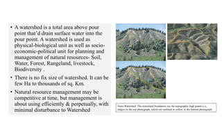
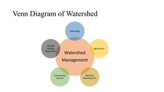
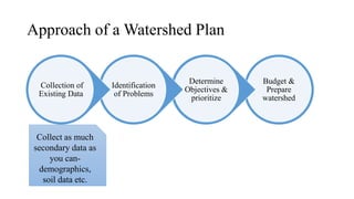
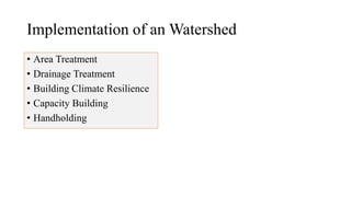
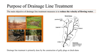
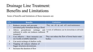
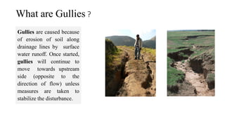
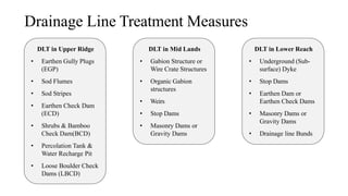
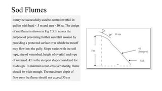
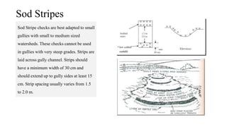
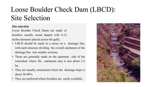
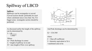
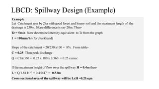
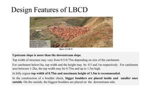
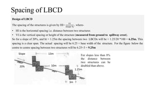
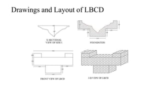
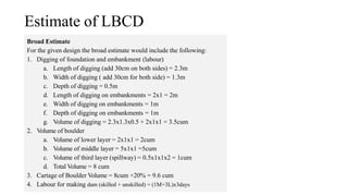
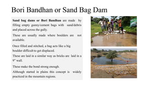
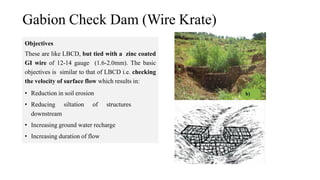
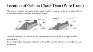
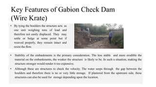
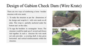
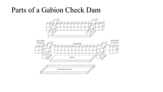
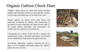
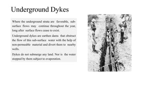
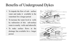
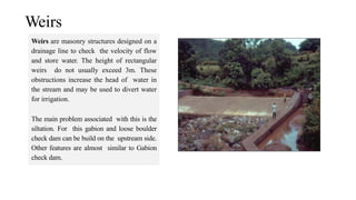
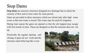
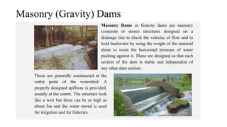
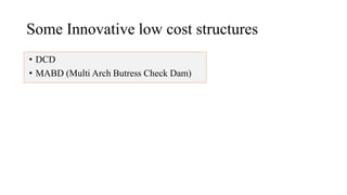
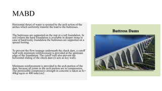
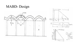
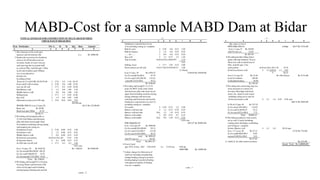
NABARD TRAINING
PROGRAM
Watershed Project
On
2nd February, 2024
Deoghar, Jharkhand
Basic terms before diving
• Topology: Natural design of surface
of land is topology
• Hydrological Cycle: Rotation of
water between earth surface,
subsurface & atmosphere is
Hydrological cycle
• Hydrological Budget: Change in
Storage = Inflow - Outflow
• A watershed is a total area above pour
point that’d drain surface water into the
pour point. A watershed is used as
physical-biological unit as well as socio-
economic-political unit for planning and
management of natural resources- Soil,
Water, Forest, Rangeland, livestock,
Biodiversity .
• There is no fix size of watershed. It can be
few Ha to thousands of sq. Km.
• Natural resource management may be
competitive at time, but management is
about using efficiently & perpetually, with
minimal disturbance to Watershed
Nano Watershed. The watershed boundaries are the topographic high points (i.e.,
ridges) in the top photograph, which are outlined in yellow in the bottom photograph
Watershed
Management
Hydrology
Agriculture
Business
Development
Community
Service
Climate
Change
Adaptation
Venn Diagram of Watershed
Approach of a Watershed Plan
Budget &
Prepare
watershed
Determine
Objectives &
prioritize
Identification
of Problems
Collection of
Existing Data
Collect as much
secondary data as
you can-
demographics,
soil data etc.
Implementation of an Watershed
• Area Treatment
• Drainage Treatment
• Building Climate Resilience
• Capacity Building
• Handholding
Purpose of Drainage Line Treatment
Drainage line treatment is primarily done by the construction of gully plugs or check dams
The main objective of drainage line treatment measures is to reduce the velocity of flowing water.
Drainage Line Treatment:
Benefits and Limitations
Some of benefits and limitations of these measures are
S.No. Benefits Limitations
1 Reduces erosion and prevents
unwanted gully formation during a flood
They can silt up and will need maintenance
2 Allows groundwater recharge and
sediment to settle out (reduces sediment
transport)
Levels of infiltration can be slowed due to silt build-
up
3 Cost effective – these measures can
use locally available materials
They can reduce the flow of lower basin water
bodies.
4 Can assist recharge of shallow wells
5 Trapping silt reduces siltation of
bigger structures downstream.
6 Increases the duration of flow
What are Gullies ?
Gullies are caused because
of erosion of soil along
drainage lines by surface
water runoff. Once started,
gullies will continue to
move towards upstream
side (opposite to the
direction of flow) unless
measures are taken to
stabilize the disturbance.
Drainage Line Treatment:
Basic Design Principles
The design of treatment structures depends upon certain principles:
• Area and Terrain : The catchment area, rainfall and slope are the
main factors affecting the design of such structures.
• Availability of Materials: The design depends upon the local conditions and
availability of raw materials and the skill for construction.
• Temporary or Permanent: The design would change depending on whether a
temporary solution is been planned or a permanent one. Temporary structures last
for 2-4 years.
• Vegetative treatment: Even the permanent structures do not last for ever. They
also have a life span. To make the structures sustain for longer time, vegetative
measures should be integrated.
Drainage Line Treatment Measures
DLT in Upper Ridge
• Earthen Gully Plugs
(EGP)
• Sod Flumes
• Sod Stripes
• Earthen Check Dam
(ECD)
• Shrubs & Bamboo
Check Dam(BCD)
• Percolation Tank &
Water Recharge Pit
• Loose Boulder Check
Dams (LBCD)
DLT in Mid Lands
• Gabion Structure or
Wire Crate Structures
• Organic Gabion
structures
• Weirs
• Stop Dams
• Masonry Dams or
Gravity Dams
DLT in Lower Reach
• Underground (Sub-
surface) Dyke
• Stop Dams
• Earthen Dam or
Earthen Check Dams
• Masonry Dams or
Gravity Dams
• Drainage line Bunds
Sod Flumes
It may be successfully used to control overfall in
gullies with head < 3 m and area <10 ha. The design
of sod flume is shown in Fig 7.3. It serves the
purpose of preventing further waterfall erosion by
providing a protected surface over which the runoff
may flow into the gully. Slope varies with the soil
type, size of watershed, height of overfall and type
of sod used. 4:1 is the steepest slope considered for
its design. To maintain a non-erosive velocity, flume
should be wide enough. The maximum depth of
flow over the flume should not exceed 30 cm
Sod Stripes
Sod Stripe checks are best adapted to small
gullies with small to medium sized
watersheds. These checks cannot be used
in gullies with very steep grades. Strips are
laid across gully channel. Strips should
have a minimum width of 30 cm and
should extend up to gully sides at least 15
cm. Strip spacing usually varies from 1.5
to 2.0 m.
Loose Boulder Check Dam (LBCD):
Site Selection
Site selection
Loose Boulder Check Dams are made of
boulders usually round shaped with 6-12
inches diameter placed across the gully.
• LBCD should be made in a series on a drainage line,
with each structure dividing the overall catchment of the
drainage line into smaller sections.
• These are generally made on the upstream side of the
watershed where the catchment area is less about 2-3
ha.
• They are usually constructed where the drainage slope is
about 30-40%.
• They are preferred where boulders are easily available.
KEY POINTS
1. The top level of a gully plug and the
base level of structure just above it
should be in a same plane.
2. Spillway should be provided to avoid overtopping.
3. The structure should be properly anchored at the bottom
and on two sides (banks) by at least 0.5m.
Loose Boulder Check Dam (LBCD):
Key Features
Spillway of LBCD
And Peak discharge can be determined by
Q = CIA/360
where
C = Run-off coefficient
I = Intensity equivalent to TcA
=catchment area in ha
Spillway
Spillways can be rectangular or curved.
Curved section should preferably be used
where catchment area is less than 1ha. For
bigger areas rectangular section should be
preferred.
As discussed earlier the length of the spillway
can be determined by
L = Q
1.84H3/2
Where
Q = Peak discharge in cumec
L = length of spillway in m and
H = max height of flow over spillway
LBCD: Spillway Design (Example)
Example
Let Catchment area be 2ha with good forest and loamy soil and the maximum length of the
drainage is 250m. Slope difference is say 20m. Then-
Tc = 5min Now determine Intensity equivalent to Tc from the graph
I = 180mm/hr (for Jharkhand)
Slope of the catchment = 20/250 x100 = 8% . From table-
C = 0.25 Then peak discharge
Q = CIA/360 = 0.25 x 180 x 2/360 = 0.25 cumec
If the maximum height of flow over the spillway H = 0.4m then-
L = Q/1.84 H3/2 = 0.4/0.47 = 0.53m
Cross sectional area of the spillway will be LxH =0.21sqm
Design Features of LBCD
Upstream slope is more than the downstream slope.
Top width of structure may vary from 0.5-0.75m depending on size of the catchment.
For catchment below1ha, top width and the height may be 0.5 and 1m respectively. For catchment
area between 1-2ha, the top width may be 0.75m and up to 1.5m high.
In hilly region top width of 0.75m and maximum height of 1.5m is recommended.
In the construction of a boulder check, bigger boulders are placed inside and smaller ones
outside. On the outside, the biggest boulders are placed on the downstream side.
figure of LBCD
Spacing of LBCD
Design of LBCD
The spacing of the structures is given by HI=
𝑉𝐼
𝑆𝑙𝑜𝑝𝑒 %
, where-
• HI is the horizontal spacing i.e. distance between two structures
• VI is the vertical spacing or height of the structure (measured from ground to spillway crest).
So for a slope of 20%, and ht = 1.25m the spacing between two LBCDs will be = 1.25/20 *100 = 6.25m. This
spacing is a clear span. The actual spacing will be 6.25 + base width of the structure. For the figure below the
centre to centre spacing between two structures will be 6.25+3 = 9.25m
10m
1.25m
20%
3m
Slope 13m For slopes less than 8%
the distance between
two structures can be
doubled than above.
Drawings and Layout of LBCD
Estimate of LBCD
Broad Estimate
For the given design the broad estimate would include the following:
1. Digging of foundation and embankment (labour)
a. Length of digging (add 30cm on both sides) = 2.3m
b. Width of digging ( add 30cm for both side) = 1.3m
c. Depth of digging = 0.5m
d. Length of digging on embankments = 2x1 = 2m
e. Width of digging on embankments = 1m
f. Depth of digging on embankments = 1m
g. Volume of digging = 2.3x1.3x0.5 + 2x1x1 = 3.5cum
2. Volume of boulder
a. Volume of lower layer = 2x1x1 = 2cum
b. Volume of middle layer = 5x1x1 =5cum
c. Volume of third layer (spillway) = 0.5x1x1x2 = 1cum
d. Total Volume = 8 cum
3. Cartage of Boulder Volume = 8cum +20% = 9.6 cum
4. Labour for making dam (skilled + unskilled) = (1M+3L)x3days
• The foundation of the dam is dug so that the length of the foundation will be more than the
length of the spillway.
• The width of the foundation depends upon the reservoir level height.
• The dam should be properly keyed across its base and up the abutments to the crest elevation.
• An adequate spillway should be provided for safe disposal of water.
• An apron of non erodible material should be provided at the base, to dissipate the energy of water
falling through the spillway.
• Proper spacing between the successive dams should be ensured
• The height of the dam should be properly planned
• Stones should be placed such that they interlock easily and form a denser structure. If small stones
are to be used they should be placed in the center and the outer surface covered with large stones to
strengthen the dams.
• Loose stone check-dams can be strengthened by covering the upstream wall and the crest with
bamboo/reed-mat.
Design and Construction of LBCD
Bori Bandhan or Sand Bag Dam
Sand bag dams or Bori Bandhan are made by
filling empty gunny/cement bags with sand/debris
and placed across the gully.
These are usually made where boulders are not
available.
Once filled and stitched, a bag acts like a big
boulder difficult to get displaced.
These are laid in a similar way as bricks are laid in a
9” wall.
These make the bond strong enough.
Although started in plains this concept is widely
practiced in the mountain regions.
Gabion Check Dam (Wire Krate)
Objectives
These are like LBCD, but tied with a zinc coated
GI wire of 12-14 gauge (1.6-2.0mm). The basic
objectives is similar to that of LBCD i.e. checking
the velocity of surface flow which results in:
• Reduction in soil erosion
• Reducing siltation of structures
downstream
• Increasing ground water recharge
• Increasing duration of flow
Location of Gabion Check Dam (Wire Krate)
These are constructed in a manner that the top of the structures should never be higher than the
embankments.
Ensure that the flow does not overtop the spillway. The peak flow therefore needs to be assessed
before hand.
The gabion structures are located in the middle reaches (sometimes at the lower reaches also) of
a watershed where the catchment area is large 20-50ha.
Key Features of Gabion Check Dam
(Wire Krate)
• By tying the boulders the structure acts as
one unit weighing tons of load and
therefore not easily displaced. They may
settle or bulge at some point but if
weaved properly, they remain intact and
resist the flow.
• Stability of the embankments is the primary consideration. The less stable and more erodible the
material on the embankments, the weaker the structure is likely to be. In such a situation, making the
structure stronger would render it too expensive.
• Although these are structures to check the velocity. The water seeps through the gap between the
boulders and therefore there is no or very little storage. If plastered from the upstream side, these
structures can also be used for storage depending upon the location.
Design of Gabion Check Dam (Wire Krate)
There are two ways of reinforcing a loose boulder
structure with wire mesh:
1. To make the structure as per the dimensions of
the design and wrap/tie it with wire mesh on all
sides. This wrap is partially anchored under the
bottom and on the sides.
2. To cage the boulders in rectangular boxes. The
structure would be made up of several such boxes
tied together. In such a structure the wire mesh
not only provides a covering shell, it also gives
horizontal and vertical reinforcements within the
structure.
Parts of a Gabion Check Dam
“Organic” gabion boxes are made from locally available
bamboo and reed strips, which are woven and tied together
to form cubic, permeable boxes to be filled with stone.
Organic gabions are placed across gully floors, and
buttressed downstream for stability. The characteristic of
the specific location determines the height and the width of
the organic gabion check-dam, and consequently the
number and size of gabions to be utilized for.
Consequently, the velocity of the run-off is reduced, and
sedimentation creates a favorable atmosphere/ environment
for the establishment of permanent biological structures.
Accordingly, appropriate vegetative structures are put in
place so as to strengthen and finally replace the "organic"
gabion that rots over time.
Organic Gabion Check Dam
Underground Dykes
Where the underground strata are favorable, sub-
surface flows may continue throughout the year,
long after surface flows cease to exist.
Underground dykes are earthen dams that obstruct
the flow of this sub-surface water with the help of
non-permeable material and divert them to nearby
wells.
Dykes do not submerge any land. Nor is the water
stopped by them subject to evaporation.
Benefits of Underground Dykes
• To impede the flow of sub- surface
water and make it available in the
watershed for a longer period
• To increase the water level in wells
by redirection of this sub-surface
water to nearby wells and tubewells
• To make surface flows in the
drainage line available for a longer
period.
Weirs
Weirs are masonry structures designed on a
drainage line to check the velocity of flow
and store water. The height of rectangular
weirs do not usually exceed 3m. These
obstructions increase the head of water in
the stream and may be used to divert water
for irrigation.
The main problem associated with this is the
siltation. For this gabion and loose boulder
check dam can be build on the upstream side.
Other features are almost similar to Gabion
check dam.
Stop Dams
Stop dams are masonry structures designed on a drainage line to check the
velocity of flow and to store water for some period.
Gates are provided in these structures which are closed only after high water
event so that rain water is stored. This water may be used for irrigation.
During lean season the gates are opened so that the silt trapped may escape
with first month of rains. These are designed so that the structure does not silt
up.
Practically the regular opening and
closing of gates do not work and the
structure starts behaving like a weir.
Masonry (Gravity) Dams
Masonry Dams or Gravity dams are masonry
(concrete or stone) structures designed on a
drainage line to check the velocity of flow and to
hold backwater by using the weight of the material
alone to resist the horizontal pressure of water
pushing against it. These are designed so that each
section of the dam is stable and independent of
any other dam section.
These are generally constructed at the
outlet point of the watershed. A
properly designed spillway is provided,
usually at the centre. The structure look
like a weir but these can be as high as
about 5m and the water stored is used
for irrigation and for fisheries.
Some Innovative low cost structures
• DCD
• MABD (Multi Arch Butress Check Dam)
MABD
Horizontal thrust of water is resisted by the arch action of the
arches which uniformly transfer the load to the buttresses.
The buttresses are supported on the mat or a raft foundation. In
soil (where the hard foundation is available in deeper strata in
case of hard/rocky foundation the buttresses are supported on a
spread footing.
To prevent the flow/seepage underneath the check dam, a cutoff
wall with minimum reinforcement is provided at the upstream
edge of the foundation. The cutoff wall also prevent the
horizontal sliding of the check dam (it acts as key wall).
Minimum reinforcement is provided in the arch portion of the
dam, because all joints in the arch portion are in compression.
The permissible compressive strength in concrete is taken as fc=
40kg/sqcm or 400 tone/cm2.
MABD- Design
MABD-Cost for a sample MABD Dam at Bidar
References & Further Reading
1. Fundamentals of Watershed Hydrology *Pamela J. Edwards1, Karl W.J.
Williard2, and Jon E. Schoonover2 1USDA Forest Service, Northern Research
Station, Parsons, WV 2Southern Illinois University, Carbondale, IL
2. Watershed Hydrology K.Suresh
3. Watershed management field manual, FAO, Rome 1998
4. https://hassan.nic.in/en/information-on-buttress-checkdam/
References

NABARD TRAINING PROGRAM_for NABARDDDMS.pdf

  • 1.
    NABARD TRAINING PROGRAM Watershed Project On 2ndFebruary, 2024 Deoghar, Jharkhand
  • 2.
    Basic terms beforediving • Topology: Natural design of surface of land is topology • Hydrological Cycle: Rotation of water between earth surface, subsurface & atmosphere is Hydrological cycle • Hydrological Budget: Change in Storage = Inflow - Outflow
  • 3.
    • A watershedis a total area above pour point that’d drain surface water into the pour point. A watershed is used as physical-biological unit as well as socio- economic-political unit for planning and management of natural resources- Soil, Water, Forest, Rangeland, livestock, Biodiversity . • There is no fix size of watershed. It can be few Ha to thousands of sq. Km. • Natural resource management may be competitive at time, but management is about using efficiently & perpetually, with minimal disturbance to Watershed Nano Watershed. The watershed boundaries are the topographic high points (i.e., ridges) in the top photograph, which are outlined in yellow in the bottom photograph
  • 4.
  • 5.
    Approach of aWatershed Plan Budget & Prepare watershed Determine Objectives & prioritize Identification of Problems Collection of Existing Data Collect as much secondary data as you can- demographics, soil data etc.
  • 6.
    Implementation of anWatershed • Area Treatment • Drainage Treatment • Building Climate Resilience • Capacity Building • Handholding
  • 7.
    Purpose of DrainageLine Treatment Drainage line treatment is primarily done by the construction of gully plugs or check dams The main objective of drainage line treatment measures is to reduce the velocity of flowing water.
  • 8.
    Drainage Line Treatment: Benefitsand Limitations Some of benefits and limitations of these measures are S.No. Benefits Limitations 1 Reduces erosion and prevents unwanted gully formation during a flood They can silt up and will need maintenance 2 Allows groundwater recharge and sediment to settle out (reduces sediment transport) Levels of infiltration can be slowed due to silt build- up 3 Cost effective – these measures can use locally available materials They can reduce the flow of lower basin water bodies. 4 Can assist recharge of shallow wells 5 Trapping silt reduces siltation of bigger structures downstream. 6 Increases the duration of flow
  • 9.
    What are Gullies? Gullies are caused because of erosion of soil along drainage lines by surface water runoff. Once started, gullies will continue to move towards upstream side (opposite to the direction of flow) unless measures are taken to stabilize the disturbance.
  • 10.
    Drainage Line Treatment: BasicDesign Principles The design of treatment structures depends upon certain principles: • Area and Terrain : The catchment area, rainfall and slope are the main factors affecting the design of such structures. • Availability of Materials: The design depends upon the local conditions and availability of raw materials and the skill for construction. • Temporary or Permanent: The design would change depending on whether a temporary solution is been planned or a permanent one. Temporary structures last for 2-4 years. • Vegetative treatment: Even the permanent structures do not last for ever. They also have a life span. To make the structures sustain for longer time, vegetative measures should be integrated.
  • 11.
    Drainage Line TreatmentMeasures DLT in Upper Ridge • Earthen Gully Plugs (EGP) • Sod Flumes • Sod Stripes • Earthen Check Dam (ECD) • Shrubs & Bamboo Check Dam(BCD) • Percolation Tank & Water Recharge Pit • Loose Boulder Check Dams (LBCD) DLT in Mid Lands • Gabion Structure or Wire Crate Structures • Organic Gabion structures • Weirs • Stop Dams • Masonry Dams or Gravity Dams DLT in Lower Reach • Underground (Sub- surface) Dyke • Stop Dams • Earthen Dam or Earthen Check Dams • Masonry Dams or Gravity Dams • Drainage line Bunds
  • 12.
    Sod Flumes It maybe successfully used to control overfall in gullies with head < 3 m and area <10 ha. The design of sod flume is shown in Fig 7.3. It serves the purpose of preventing further waterfall erosion by providing a protected surface over which the runoff may flow into the gully. Slope varies with the soil type, size of watershed, height of overfall and type of sod used. 4:1 is the steepest slope considered for its design. To maintain a non-erosive velocity, flume should be wide enough. The maximum depth of flow over the flume should not exceed 30 cm
  • 13.
    Sod Stripes Sod Stripechecks are best adapted to small gullies with small to medium sized watersheds. These checks cannot be used in gullies with very steep grades. Strips are laid across gully channel. Strips should have a minimum width of 30 cm and should extend up to gully sides at least 15 cm. Strip spacing usually varies from 1.5 to 2.0 m.
  • 14.
    Loose Boulder CheckDam (LBCD): Site Selection Site selection Loose Boulder Check Dams are made of boulders usually round shaped with 6-12 inches diameter placed across the gully. • LBCD should be made in a series on a drainage line, with each structure dividing the overall catchment of the drainage line into smaller sections. • These are generally made on the upstream side of the watershed where the catchment area is less about 2-3 ha. • They are usually constructed where the drainage slope is about 30-40%. • They are preferred where boulders are easily available.
  • 15.
    KEY POINTS 1. Thetop level of a gully plug and the base level of structure just above it should be in a same plane. 2. Spillway should be provided to avoid overtopping. 3. The structure should be properly anchored at the bottom and on two sides (banks) by at least 0.5m. Loose Boulder Check Dam (LBCD): Key Features
  • 16.
    Spillway of LBCD AndPeak discharge can be determined by Q = CIA/360 where C = Run-off coefficient I = Intensity equivalent to TcA =catchment area in ha Spillway Spillways can be rectangular or curved. Curved section should preferably be used where catchment area is less than 1ha. For bigger areas rectangular section should be preferred. As discussed earlier the length of the spillway can be determined by L = Q 1.84H3/2 Where Q = Peak discharge in cumec L = length of spillway in m and H = max height of flow over spillway
  • 17.
    LBCD: Spillway Design(Example) Example Let Catchment area be 2ha with good forest and loamy soil and the maximum length of the drainage is 250m. Slope difference is say 20m. Then- Tc = 5min Now determine Intensity equivalent to Tc from the graph I = 180mm/hr (for Jharkhand) Slope of the catchment = 20/250 x100 = 8% . From table- C = 0.25 Then peak discharge Q = CIA/360 = 0.25 x 180 x 2/360 = 0.25 cumec If the maximum height of flow over the spillway H = 0.4m then- L = Q/1.84 H3/2 = 0.4/0.47 = 0.53m Cross sectional area of the spillway will be LxH =0.21sqm
  • 18.
    Design Features ofLBCD Upstream slope is more than the downstream slope. Top width of structure may vary from 0.5-0.75m depending on size of the catchment. For catchment below1ha, top width and the height may be 0.5 and 1m respectively. For catchment area between 1-2ha, the top width may be 0.75m and up to 1.5m high. In hilly region top width of 0.75m and maximum height of 1.5m is recommended. In the construction of a boulder check, bigger boulders are placed inside and smaller ones outside. On the outside, the biggest boulders are placed on the downstream side. figure of LBCD
  • 19.
    Spacing of LBCD Designof LBCD The spacing of the structures is given by HI= 𝑉𝐼 𝑆𝑙𝑜𝑝𝑒 % , where- • HI is the horizontal spacing i.e. distance between two structures • VI is the vertical spacing or height of the structure (measured from ground to spillway crest). So for a slope of 20%, and ht = 1.25m the spacing between two LBCDs will be = 1.25/20 *100 = 6.25m. This spacing is a clear span. The actual spacing will be 6.25 + base width of the structure. For the figure below the centre to centre spacing between two structures will be 6.25+3 = 9.25m 10m 1.25m 20% 3m Slope 13m For slopes less than 8% the distance between two structures can be doubled than above.
  • 20.
  • 21.
    Estimate of LBCD BroadEstimate For the given design the broad estimate would include the following: 1. Digging of foundation and embankment (labour) a. Length of digging (add 30cm on both sides) = 2.3m b. Width of digging ( add 30cm for both side) = 1.3m c. Depth of digging = 0.5m d. Length of digging on embankments = 2x1 = 2m e. Width of digging on embankments = 1m f. Depth of digging on embankments = 1m g. Volume of digging = 2.3x1.3x0.5 + 2x1x1 = 3.5cum 2. Volume of boulder a. Volume of lower layer = 2x1x1 = 2cum b. Volume of middle layer = 5x1x1 =5cum c. Volume of third layer (spillway) = 0.5x1x1x2 = 1cum d. Total Volume = 8 cum 3. Cartage of Boulder Volume = 8cum +20% = 9.6 cum 4. Labour for making dam (skilled + unskilled) = (1M+3L)x3days
  • 22.
    • The foundationof the dam is dug so that the length of the foundation will be more than the length of the spillway. • The width of the foundation depends upon the reservoir level height. • The dam should be properly keyed across its base and up the abutments to the crest elevation. • An adequate spillway should be provided for safe disposal of water. • An apron of non erodible material should be provided at the base, to dissipate the energy of water falling through the spillway. • Proper spacing between the successive dams should be ensured • The height of the dam should be properly planned • Stones should be placed such that they interlock easily and form a denser structure. If small stones are to be used they should be placed in the center and the outer surface covered with large stones to strengthen the dams. • Loose stone check-dams can be strengthened by covering the upstream wall and the crest with bamboo/reed-mat. Design and Construction of LBCD
  • 23.
    Bori Bandhan orSand Bag Dam Sand bag dams or Bori Bandhan are made by filling empty gunny/cement bags with sand/debris and placed across the gully. These are usually made where boulders are not available. Once filled and stitched, a bag acts like a big boulder difficult to get displaced. These are laid in a similar way as bricks are laid in a 9” wall. These make the bond strong enough. Although started in plains this concept is widely practiced in the mountain regions.
  • 24.
    Gabion Check Dam(Wire Krate) Objectives These are like LBCD, but tied with a zinc coated GI wire of 12-14 gauge (1.6-2.0mm). The basic objectives is similar to that of LBCD i.e. checking the velocity of surface flow which results in: • Reduction in soil erosion • Reducing siltation of structures downstream • Increasing ground water recharge • Increasing duration of flow
  • 25.
    Location of GabionCheck Dam (Wire Krate) These are constructed in a manner that the top of the structures should never be higher than the embankments. Ensure that the flow does not overtop the spillway. The peak flow therefore needs to be assessed before hand. The gabion structures are located in the middle reaches (sometimes at the lower reaches also) of a watershed where the catchment area is large 20-50ha.
  • 26.
    Key Features ofGabion Check Dam (Wire Krate) • By tying the boulders the structure acts as one unit weighing tons of load and therefore not easily displaced. They may settle or bulge at some point but if weaved properly, they remain intact and resist the flow. • Stability of the embankments is the primary consideration. The less stable and more erodible the material on the embankments, the weaker the structure is likely to be. In such a situation, making the structure stronger would render it too expensive. • Although these are structures to check the velocity. The water seeps through the gap between the boulders and therefore there is no or very little storage. If plastered from the upstream side, these structures can also be used for storage depending upon the location.
  • 27.
    Design of GabionCheck Dam (Wire Krate) There are two ways of reinforcing a loose boulder structure with wire mesh: 1. To make the structure as per the dimensions of the design and wrap/tie it with wire mesh on all sides. This wrap is partially anchored under the bottom and on the sides. 2. To cage the boulders in rectangular boxes. The structure would be made up of several such boxes tied together. In such a structure the wire mesh not only provides a covering shell, it also gives horizontal and vertical reinforcements within the structure.
  • 28.
    Parts of aGabion Check Dam
  • 29.
    “Organic” gabion boxesare made from locally available bamboo and reed strips, which are woven and tied together to form cubic, permeable boxes to be filled with stone. Organic gabions are placed across gully floors, and buttressed downstream for stability. The characteristic of the specific location determines the height and the width of the organic gabion check-dam, and consequently the number and size of gabions to be utilized for. Consequently, the velocity of the run-off is reduced, and sedimentation creates a favorable atmosphere/ environment for the establishment of permanent biological structures. Accordingly, appropriate vegetative structures are put in place so as to strengthen and finally replace the "organic" gabion that rots over time. Organic Gabion Check Dam
  • 30.
    Underground Dykes Where theunderground strata are favorable, sub- surface flows may continue throughout the year, long after surface flows cease to exist. Underground dykes are earthen dams that obstruct the flow of this sub-surface water with the help of non-permeable material and divert them to nearby wells. Dykes do not submerge any land. Nor is the water stopped by them subject to evaporation.
  • 31.
    Benefits of UndergroundDykes • To impede the flow of sub- surface water and make it available in the watershed for a longer period • To increase the water level in wells by redirection of this sub-surface water to nearby wells and tubewells • To make surface flows in the drainage line available for a longer period.
  • 32.
    Weirs Weirs are masonrystructures designed on a drainage line to check the velocity of flow and store water. The height of rectangular weirs do not usually exceed 3m. These obstructions increase the head of water in the stream and may be used to divert water for irrigation. The main problem associated with this is the siltation. For this gabion and loose boulder check dam can be build on the upstream side. Other features are almost similar to Gabion check dam.
  • 33.
    Stop Dams Stop damsare masonry structures designed on a drainage line to check the velocity of flow and to store water for some period. Gates are provided in these structures which are closed only after high water event so that rain water is stored. This water may be used for irrigation. During lean season the gates are opened so that the silt trapped may escape with first month of rains. These are designed so that the structure does not silt up. Practically the regular opening and closing of gates do not work and the structure starts behaving like a weir.
  • 34.
    Masonry (Gravity) Dams MasonryDams or Gravity dams are masonry (concrete or stone) structures designed on a drainage line to check the velocity of flow and to hold backwater by using the weight of the material alone to resist the horizontal pressure of water pushing against it. These are designed so that each section of the dam is stable and independent of any other dam section. These are generally constructed at the outlet point of the watershed. A properly designed spillway is provided, usually at the centre. The structure look like a weir but these can be as high as about 5m and the water stored is used for irrigation and for fisheries.
  • 35.
    Some Innovative lowcost structures • DCD • MABD (Multi Arch Butress Check Dam)
  • 36.
    MABD Horizontal thrust ofwater is resisted by the arch action of the arches which uniformly transfer the load to the buttresses. The buttresses are supported on the mat or a raft foundation. In soil (where the hard foundation is available in deeper strata in case of hard/rocky foundation the buttresses are supported on a spread footing. To prevent the flow/seepage underneath the check dam, a cutoff wall with minimum reinforcement is provided at the upstream edge of the foundation. The cutoff wall also prevent the horizontal sliding of the check dam (it acts as key wall). Minimum reinforcement is provided in the arch portion of the dam, because all joints in the arch portion are in compression. The permissible compressive strength in concrete is taken as fc= 40kg/sqcm or 400 tone/cm2.
  • 37.
  • 38.
    MABD-Cost for asample MABD Dam at Bidar
  • 39.
    References & FurtherReading 1. Fundamentals of Watershed Hydrology *Pamela J. Edwards1, Karl W.J. Williard2, and Jon E. Schoonover2 1USDA Forest Service, Northern Research Station, Parsons, WV 2Southern Illinois University, Carbondale, IL 2. Watershed Hydrology K.Suresh 3. Watershed management field manual, FAO, Rome 1998 4. https://hassan.nic.in/en/information-on-buttress-checkdam/ References