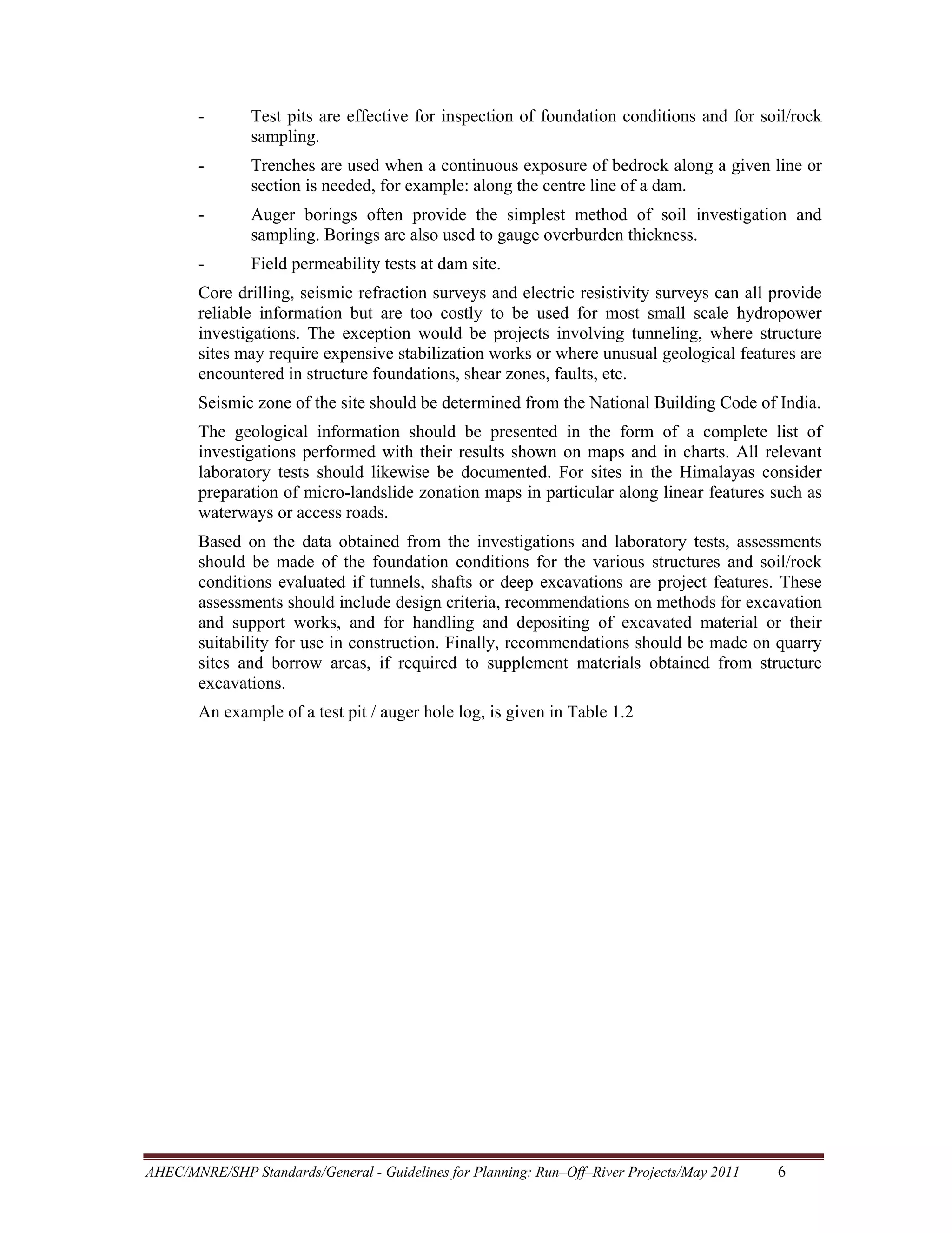
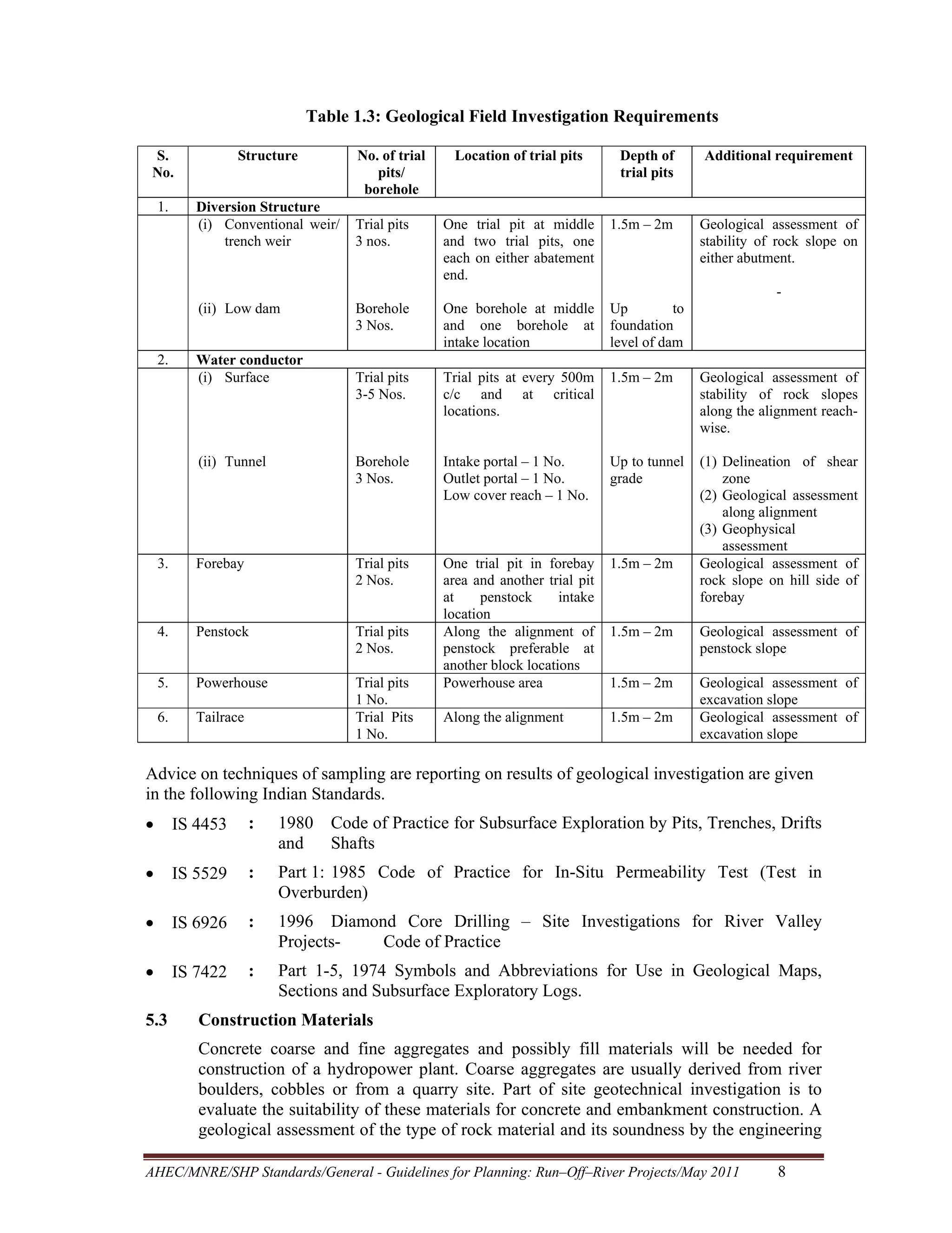
This document provides guidelines for planning site reconnaissance and detailed field investigations for small hydroelectric projects. It recommends establishing a survey control network and conducting topographic surveys, geological investigations, and materials searches. Topographic surveys should map reservoirs, structures, waterways, and infrastructure. Geological investigations should identify subsurface conditions through test pits, trenches, and samples. These investigations provide essential data for design and cost estimates.
Reconnaissance for Hydrographic Surveying ProjectNzar Braim
Reconnaissance for Hydrographic
Surveying Project
This report talks about how the reconnaissance will be and it is effectively important the place that we survey and observation so the surveyor should prepare himself or herself for the project visiting site and site survey and planning and so on.
Observer visiting the site many times daily to see what is the situation and the condition and booking his or her notes recording them such as is the site ready to start the observation? Or is the site has safety to start? I mean replace safety conditions and also must have collected all this information and choose which instrument this site or this project and many other conditions should be considered after all above that I have mentioned he or she decides to start and beginning Project and surveying or not. This is the idea or this the outline recognizes.
The first phase of the Northern Collector Water Tunnel project is located along the eastern fringes of the Aberdare Conservation area approximately 60 kilometer north of Nairobi county.
The works are located in Kangema and Kigumo sub counties of Murang'a county
Runoff modelling using hec hms for rural watershedEditorIJAERD
Due to climate change it is very essential to do hydrological modelling. Reliable models are essential for planning,
developmental works, prediction and safety of the population. Hydrological models are used to determine catchment
discharge/flow through an efficient way. HEC-HM (Hydrological engineering centre Hydrological modelling system) is
one of hydrological modelling tool developed by United States army corps of engineer (USACE) for event as well as for
continuous simulations. Models, especially continuous simulations are useful for future predictions of stream flow due to
land-use changes or extreme events phenomenon. In this study continuous hydrologic modellingwas carried out using
HEC HMS modelling tool.
Deficit and Constant Loss methods with Clark transform methods were selected. The calibrated model (period
1986-1988) was validated with data set of the period of 2009-2013. Study concluded that the model recommended and
can be used for stated River as decision support tool in the design and operation.
This presentation was given as part of the EPA-funded Catchment Science and Management Course focusing on Integrated Catchment Management, held in June 2015. This course was delivered by RPS Consultants. If you have any queries or comments, or wish to use the material in this presentation, please contact catchments@epa.ie
It is increasingly being recognised internationally that integrated catchment management (ICM) is a useful organising framework for tackling the ongoing challenge of balancing sustainable use and development of our natural resource, against achieving environmental goals. The basic principles of ICM (Williams, 2012) are to:
• Take a holistic and integrated approach to the management of land, biodiversity, water and community resources at the water catchment scale;
• Involve communities in planning and managing their landscapes; and
• Find a balance between resource use and resource conservation
ICM is now well established in Australia, New Zealand, and the United States. In Europe the ICM approach has been proposed as being required to achieve effective water and catchment management, and is the approach being promoted by DEFRA for the UK, where it is called the “Catchment Based Approach” (CaBA). The principles and methodologies behind ICM sit well within the context of the Water Framework Directive with its aims and objectives for good water quality, sustainable development and public participation in water resource management. In Ireland it is proposed that the ICM approach will underlie the work and philosophy in developing and implementing future River Basin Management Plans.
Impacts of hydropower on farmers' livelihoods in the Sre Pok River in Vietnam...CPWF Mekong
By Chau Thi Minh Long, The Western Highlands Agriculture and Forestry Science and Technology Institute, M-POWER Fellow
Presented at the Mekong Forum on Water, Food and Energy
Phnom Penh, Cambodia
December 7-9, 2011
Session 8a: Presenting the Work of the M-POWER Fellows
Practices in Planning, Design and Construction of Head Race Tunnel of a Hydro...Mohit Shukla
This paper has been selected for oral presentation as well as inclusion in the conference proceedings of the ICCCGE 2016 : 18th International Conference on Civil,Construction and Geological Engineering held in Toronto, Canada during June,
13-14, 2016. This paper was also able to find a position in the international conference of Dams and Hydropower held at Laos in May 2016.
IPWEA Groundwater Separation Distances - Jun 17 - UrbAquaRichard Connell
Draft IPWEA Specification - Separation Distances for Groundwater Controlled Urban Development. Presented by Helen Brookes from UrbAqua at Engineers Australia WA - June 2017
Kubernetes & AI - Beauty and the Beast !?! @KCD Istanbul 2024Tobias Schneck
As AI technology is pushing into IT I was wondering myself, as an “infrastructure container kubernetes guy”, how get this fancy AI technology get managed from an infrastructure operational view? Is it possible to apply our lovely cloud native principals as well? What benefit’s both technologies could bring to each other?
Let me take this questions and provide you a short journey through existing deployment models and use cases for AI software. On practical examples, we discuss what cloud/on-premise strategy we may need for applying it to our own infrastructure to get it to work from an enterprise perspective. I want to give an overview about infrastructure requirements and technologies, what could be beneficial or limiting your AI use cases in an enterprise environment. An interactive Demo will give you some insides, what approaches I got already working for real.
State of ICS and IoT Cyber Threat Landscape Report 2024 previewPrayukth K V
The IoT and OT threat landscape report has been prepared by the Threat Research Team at Sectrio using data from Sectrio, cyber threat intelligence farming facilities spread across over 85 cities around the world. In addition, Sectrio also runs AI-based advanced threat and payload engagement facilities that serve as sinks to attract and engage sophisticated threat actors, and newer malware including new variants and latent threats that are at an earlier stage of development.
The latest edition of the OT/ICS and IoT security Threat Landscape Report 2024 also covers:
State of global ICS asset and network exposure
Sectoral targets and attacks as well as the cost of ransom
Global APT activity, AI usage, actor and tactic profiles, and implications
Rise in volumes of AI-powered cyberattacks
Major cyber events in 2024
Malware and malicious payload trends
Cyberattack types and targets
Vulnerability exploit attempts on CVEs
Attacks on counties – USA
Expansion of bot farms – how, where, and why
In-depth analysis of the cyber threat landscape across North America, South America, Europe, APAC, and the Middle East
Why are attacks on smart factories rising?
Cyber risk predictions
Axis of attacks – Europe
Systemic attacks in the Middle East
Download the full report from here:
https://sectrio.com/resources/ot-threat-landscape-reports/sectrio-releases-ot-ics-and-iot-security-threat-landscape-report-2024/
Generating a custom Ruby SDK for your web service or Rails API using Smithyg2nightmarescribd
Have you ever wanted a Ruby client API to communicate with your web service? Smithy is a protocol-agnostic language for defining services and SDKs. Smithy Ruby is an implementation of Smithy that generates a Ruby SDK using a Smithy model. In this talk, we will explore Smithy and Smithy Ruby to learn how to generate custom feature-rich SDKs that can communicate with any web service, such as a Rails JSON API.
DevOps and Testing slides at DASA ConnectKari Kakkonen
My and Rik Marselis slides at 30.5.2024 DASA Connect conference. We discuss about what is testing, then what is agile testing and finally what is Testing in DevOps. Finally we had lovely workshop with the participants trying to find out different ways to think about quality and testing in different parts of the DevOps infinity loop.
Builder.ai Founder Sachin Dev Duggal's Strategic Approach to Create an Innova...Ramesh Iyer
In today's fast-changing business world, Companies that adapt and embrace new ideas often need help to keep up with the competition. However, fostering a culture of innovation takes much work. It takes vision, leadership and willingness to take risks in the right proportion. Sachin Dev Duggal, co-founder of Builder.ai, has perfected the art of this balance, creating a company culture where creativity and growth are nurtured at each stage.
Elevating Tactical DDD Patterns Through Object CalisthenicsDorra BARTAGUIZ
After immersing yourself in the blue book and its red counterpart, attending DDD-focused conferences, and applying tactical patterns, you're left with a crucial question: How do I ensure my design is effective? Tactical patterns within Domain-Driven Design (DDD) serve as guiding principles for creating clear and manageable domain models. However, achieving success with these patterns requires additional guidance. Interestingly, we've observed that a set of constraints initially designed for training purposes remarkably aligns with effective pattern implementation, offering a more ‘mechanical’ approach. Let's explore together how Object Calisthenics can elevate the design of your tactical DDD patterns, offering concrete help for those venturing into DDD for the first time!
Dev Dives: Train smarter, not harder – active learning and UiPath LLMs for do...UiPathCommunity
💥 Speed, accuracy, and scaling – discover the superpowers of GenAI in action with UiPath Document Understanding and Communications Mining™:
See how to accelerate model training and optimize model performance with active learning
Learn about the latest enhancements to out-of-the-box document processing – with little to no training required
Get an exclusive demo of the new family of UiPath LLMs – GenAI models specialized for processing different types of documents and messages
This is a hands-on session specifically designed for automation developers and AI enthusiasts seeking to enhance their knowledge in leveraging the latest intelligent document processing capabilities offered by UiPath.
Speakers:
👨🏫 Andras Palfi, Senior Product Manager, UiPath
👩🏫 Lenka Dulovicova, Product Program Manager, UiPath
Neuro-symbolic is not enough, we need neuro-*semantic*Frank van Harmelen
Neuro-symbolic (NeSy) AI is on the rise. However, simply machine learning on just any symbolic structure is not sufficient to really harvest the gains of NeSy. These will only be gained when the symbolic structures have an actual semantics. I give an operational definition of semantics as “predictable inference”.
All of this illustrated with link prediction over knowledge graphs, but the argument is general.
LF Energy Webinar: Electrical Grid Modelling and Simulation Through PowSyBl -...DanBrown980551
Do you want to learn how to model and simulate an electrical network from scratch in under an hour?
Then welcome to this PowSyBl workshop, hosted by Rte, the French Transmission System Operator (TSO)!
During the webinar, you will discover the PowSyBl ecosystem as well as handle and study an electrical network through an interactive Python notebook.
PowSyBl is an open source project hosted by LF Energy, which offers a comprehensive set of features for electrical grid modelling and simulation. Among other advanced features, PowSyBl provides:
- A fully editable and extendable library for grid component modelling;
- Visualization tools to display your network;
- Grid simulation tools, such as power flows, security analyses (with or without remedial actions) and sensitivity analyses;
The framework is mostly written in Java, with a Python binding so that Python developers can access PowSyBl functionalities as well.
What you will learn during the webinar:
- For beginners: discover PowSyBl's functionalities through a quick general presentation and the notebook, without needing any expert coding skills;
- For advanced developers: master the skills to efficiently apply PowSyBl functionalities to your real-world scenarios.
Slack (or Teams) Automation for Bonterra Impact Management (fka Social Soluti...Jeffrey Haguewood
Sidekick Solutions uses Bonterra Impact Management (fka Social Solutions Apricot) and automation solutions to integrate data for business workflows.
We believe integration and automation are essential to user experience and the promise of efficient work through technology. Automation is the critical ingredient to realizing that full vision. We develop integration products and services for Bonterra Case Management software to support the deployment of automations for a variety of use cases.
This video focuses on the notifications, alerts, and approval requests using Slack for Bonterra Impact Management. The solutions covered in this webinar can also be deployed for Microsoft Teams.
Interested in deploying notification automations for Bonterra Impact Management? Contact us at sales@sidekicksolutionsllc.com to discuss next steps.
Epistemic Interaction - tuning interfaces to provide information for AI supportAlan Dix
Paper presented at SYNERGY workshop at AVI 2024, Genoa, Italy. 3rd June 2024
https://alandix.com/academic/papers/synergy2024-epistemic/
As machine learning integrates deeper into human-computer interactions, the concept of epistemic interaction emerges, aiming to refine these interactions to enhance system adaptability. This approach encourages minor, intentional adjustments in user behaviour to enrich the data available for system learning. This paper introduces epistemic interaction within the context of human-system communication, illustrating how deliberate interaction design can improve system understanding and adaptation. Through concrete examples, we demonstrate the potential of epistemic interaction to significantly advance human-computer interaction by leveraging intuitive human communication strategies to inform system design and functionality, offering a novel pathway for enriching user-system engagements.
1. Version 2
STANDARDS/MANUALS/
GUIDELINES FOR
SMALL HYDRO DEVELOPMENT
General–
Planning: Run–Off–River Projects
Lead Organization:
Sponsor:
Alternate Hydro Energy Center
Indian Institute of Technology Roorkee
Ministry of New and Renewable Energy
Govt. of India
May 2011
2. CONTENTS
S.No.
TITLE
Page No.
1. INTRODUCTION
1
2. SCOPE
1
3. OTHER DATA REQUIREMENTS
1
4. RECONNAISSANCE
1
5. DETAILED SITE INVESTIGATIONS
3
5.1. TOPOGRAPHIC SURVEY
3
5.1.1. Reservoir Survey
3
5.1.2. Diversion Dam And Head Works
4
5.1.3. River Downstream Of Diversion Dam
4
5.1.4. Waterway Survey
4
5.1.5. Structure Surveys
4
5.1.6. River Downstream Of Tailrace Outlet
4
5.1.7. Access Roads, T.L. Routes And Project Infrastructure
4
5.1.8. Flow Gauging
4
5.2. GEOLOGICAL INVESTIGATIONS
5
5.3. CONSTRUCTION MATERIALS
8
6. POWER MARKET SURVEY
9
7. REFERENCES
9
7.1. OTHER REFERENCES
10
3. GUIDELINES FOR PLANNING THE PROJECTS ON RUN OF
RIVER PROJECTS
1
INTRODUCTION
Design of a hydropower facility requires the collection of a substantial data base. Data
required may be classified into the following categories:
•
Hydrology
•
Sediments
•
Power market survey
•
Topographic surveys
•
Geology
•
Construction material
•
Materials testing
Data collection is an on going process starting with the preliminary phase of studies, as
below:
Step 1: Preliminary Studies: Collection and review of all available and pertinent
documents. Air photo or G.I.S. interpretation is often employed at this stage to
assess site features.
Step 2: Reconnaissance survey: On site visit to assess site conditions, to confirm basic
findings from desk / map studies and to identify the scope of detailed site
investigations.
Step 3: Detailed site investigations to develop data for final layouts, feasibility (and
detailed designs) and preparation of cost estimates and construction schedules.
Scheduling of the field investigation program during the dry reason is recommended as
site access will be easier and crossing of rivers less difficult and dangerous.
2
SCOPE
The scope of this section provides guidelines on the planning of site reconnaissance and
detailed field investigation programs.
3
OTHER DATA REQUIREMENTS
Guidelines on other data requirements are given in the following sections of this
Standard, as below:
•
:
Section 1.4
•
Sediment
:
Section 2.2.3 / 2.1
•
4
Hydrology
Power and Market Survey:
Section 1.2
RECONNAISSANCE
The purpose of a site reconnaissance visit is to gain an understanding of site
characteristics, potential problems as well as solutions, and for input to site selection of
the main project structures.
AHEC/MNRE/SHP Standards/General - Guidelines for Planning: Run–Off–River Projects/May 2011
1
4. Prior to undertaking a site reconnaissance visit available data should be reviewed and
preliminary conceptual designs prepared and laid out on available mapping for guidance
during the field visit. It is further recommended that an outline of the preliminary
studies report be made at this time and a check list prepared from it before going into
the field. This will help to identify important information that is lacking in order to
search for it during the site visit.
The site visit provides an opportunity to obtain an appreciation of site topography, flow
regime, geology and access for roads and transmission lines. From these on-site
observations it is often possible to identify practical locations for temporary facilities,
head-works, desilting tank and powerhouse and to decide the side of the river best suited
for routing of the waterways, preliminary access roads and transmission line (T.L.)
routes. These locations, their elevations and co-ordinates can be determined with
portable GPS equipment. GPS equipment capable of giving elevation and spatial
measurement with accuracies of +/- 0.3m and 1.0 m respectively (or better) should be
used. It is also recommended that the inspection team include at least three
professionals: a hydrologist, an engineering geologist/geotechnical engineer and a
hydropower engineer. It is also recommended that the team include local
representatives. Their practical knowledge of the area and its people could be
invaluable. This initial contact could also be an opportunity for developing the interest
and support of local residents for the project. Typically, a field visit will require 1-3
days depending on the remoteness, size and complexity of the site.
The following generic checklist is recommended for assistance in planning the
reconnaissance visit.
Table 1.1:
Check List on Site Conditions
Factors to consider:
•
Climate
•
Condition of main road to the project site, weight and width limitations on
bridges.
•
Access and site roads and suitable areas for structures, stock-pile, waste disposal.
•
Routes for transmission / distribution lines.
•
Visual assessment of foundation conditions and slope stability along waterways
and at structure sites.
•
Developable head.
•
Penstock / head length ratio.
•
Availability of construction
impermeable fill, as required)
•
Local services and skills available.
•
High water marks in tail water and head pond areas.
•
Location of important lateral water courses
•
Population of villages within the probable service radius of the plant and types
of industries, existing or planned.
•
Location of buildings or other structures that may require relocation, etc.
materials
(sand,
aggregates,
lumber
AHEC/MNRE/SHP Standards/General - Guidelines for Planning: Run–Off–River Projects/May 2011
2
and
5. A site reconnaissance relies mainly upon visual assessment of site conditions and
therefore it is important that the findings be supported by photographs of key features.
Finally, it is recommended that a site reconnaissance report be prepared outlining the
observations and findings from site reconnaissance. At this stage a preliminary report is
usually prepared combining the findings of office studies and site reconnaissance visit.
If this report concludes that the project is likely to be viable then a feasibility study
would be recommended and a scope of work prepared for further office and field
investigations. Projects deemed infeasible would usually be abandoned at the stage
although a report summarizing these findings should still be prepared to record the work
done for future reference.
5
DETAILED SITE INVESTIGATIONS
Detailed site investigations usually comprise the following activities:
•
•
Geotechnical investigations
•
5.1
Topographic survey
Construction materials search
Topographic Survey
The scope of topo mapping should be decided following the field reconnaissance when
locations of major structures have been approximately decided. In general, the extent of
mapping should be sufficient to cover all alternatives envisaged and to allow for
reasonable realignments of structures, waterways, access roads and transmission line
(T.L) routes.
It is recommended that the first activity in the topographic survey program be the
establishment of a control network of reference points and benchmarks. The network
should provide coverage of the complete hydro scheme from intake to tailrace channel
including related switchyards, laydown (stockpile) areas and site roads. While the initial
use of this network is for control of topographic surveying, the same benchmarks will
eventually be needed for control of construction. Much difficulty and expense can be
avoided later, in the construction phase, if these benchmarks are solidly installed so that
they will be available whenever construction starts up: within months or years, as the
case may be. Once the benchmarks have been installed a first order survey should be
carried out to establish elevations and coordinates at each control point. If possible the
control survey should be based on the survey of India, for new run-off river schemes, or
based on existing project grids for toe of dam or canal fall schemes.
The following notes discuss the scope of topographic surveying as it applies to various
components of a typical small hydro project. The suggested scope attempts to be
comprehensive; however, the scope can be tailored to fit the requirements of a particular
project.
5.1.1 Reservoir Survey
A cross section survey should be carried out upstream of the diversion dam to
establish the limits of the head pond reservoir, extent of over bank flooding (if
any) and reservoir area and volume. The survey should extend upstream to the
point where the river bottom elevation and reservoir maximum flood level are
the same. Spacing between cross sections should be between 2 to 5 times the
breadth of the river channel, but not greater than 500m apart. Cross sections
should extent to the maximum flood level (MFL) plus 1.0 m (plus 10.0 m for
potentially unstable bank slopes especially in areas likely to affect village homes
AHEC/MNRE/SHP Standards/General - Guidelines for Planning: Run–Off–River Projects/May 2011
3
6. or fields). Current water levels and high water marks should be noted. Cross
sections should be referenced to a control / centre line. If water flow is too fast
or too deep for wading, the depth should be estimated visually or by sounding
from a boat.
5.1.2 Diversion dam and Head works
Three to five cross sections should be taken through the dam centre line and
upstream and downstream of the dam. Additional cross-section may be required
to cover the river channel area in front of the head works. Surface mapping
should be sufficient to cover dam abutment and head regulator (intake) areas.
5.1.3 River downstream of diversion dam
Survey of the river channel downstream of the dam is required to establish a
head / discharge rating curve at the toe of the diversion dam. The survey should
also be continued far enough downstream to establish an adequate drop between
the desilter and river for input to siting of the desilter. The hydro engineer should
advise the extent (length) of survey required.
5.1.4 Waterway survey
It is recommended that a control traverse be laid out along the route of the
waterways. This traverse should be traced along the contour corresponding to the
normal water level in the canals. Cross sections should extend (typically) 30m
up hill and 20m down hill as appropriate. Cross sections should be located at 50
m intervals, at abrupt changes in topography and at gullies (nalas) crossing the
waterway centre line. A minimum of three cross sections should also be taken at
gully (nala) crossings sufficient to describe these features for design of culverts.
It is preferable that the control traverse be “closed” on a pre-established survey
control point. This traverse will also be useful for tying in geological features,
test pits, etc.
5.1.5
Structure Surveys
Structure surveys should provide coverage for the structure plan forms
(footprints) with allowances for re-alignment, slope stabilization works or
retaining walls, if required.
5.1.6 River downstream of tailrace outlet
A river cross section survey should be carried out below the tailrace outlet
sufficient to permit establishment of a head / discharge rating curve at this
location. Spacing and extent of survey would follow suggestions given in (c)
above.
5.1.7 Access roads, T.L. routes and project infrastructure
Routes surveys along access roads and T.L. routes should also be included. It is
also desirable to survey project infrastructure sites such as: stockpile areas, camp
and office areas, disposal areas and temporary (construction) roads. In some
cases pre-existing quarries or commercial areas may be available for stockpiling,
offices and the like. Surveys of such areas would not be required.
5.1.8 Flow gauging
If practical, it is desirable to carry out flow measurements for low, medium and
high flows to aid in establishing flow rating curves at tailrace and diversion dam.
Such measurements can be done conveniently from a bridge crossing the river
AHEC/MNRE/SHP Standards/General - Guidelines for Planning: Run–Off–River Projects/May 2011
4
7. and located close to the project site, by wading or from a boat (in areas of slow
flow).
It is also recommended that surveyors note on their maps all important cultural features
(villages, houses, roads and foot paths) and ground conditions (ephemeral or perennial)
streams, grass land, sparse or heavy forest, soil type, broken or solid rock). Date of
survey should be noted on all cross section plots and maps.
Measurements taken in the field should be plotted up in the form of longitudinal profiles
and cross-section for linear facilities such as waterways, roads and transmission lines. In
addition contour maps should be prepared covering all components of the development.
The following contour intervals are suggested:
-
Steep areas, such as hillside canals: 2.0 m intervals
-
Moderate slopes:
1.0 m intervals
-
Flat areas:
0.5 m intervals
Finally, it is recommended that all cross section and mapping developed in the
topographic survey be produced in CADD files to facilitate reproduction at appropriate
scales for use in preparation of plans and construction drawings.
5.2
Geological Investigations
The first step in a geological investigation of a project site is the preparation of a
geological map. Such a map is usually based on surface observations supplemented by
information from laboratory analyses of collected samples. When the geology is
complex or bedrock not exposed, subsurface investigation may be needed. However,
such investigations are very costly are rarely justified for small hydro projects. For small
hydro schemes much of the appraisal of site geologic conditions will be based upon
informed visual inspection of site features. This should be done by an experienced
engineering geologist; preferably one familiar with geology of the area.
According to the specific geological conditions of the site, the scope of site
investigations may vary considerably. A well thought out and flexible program should
be established before subsurface investigations begin, including a definition of their
purpose. Geological features likely to necessitate special attention are summarized
below :
-
Major geological features affecting the site, such as faults, fractured and shear
zones and the contacts between the different types of rock.
-
Areas of deeply weathered or heavily altered zones.
-
Permeable strata, large open cracks, limestone caves or fissures and location of
springs.
-
Active processes showing evidence of erosion, slope-creep, screes, landslides,
rockfalls and rockbursts.
The characteristics of theses features should be elucidated and implications for design
established. Where bedrock exposures are limited geophysical methods of investigation
may be required depending on the importance of the structure. Sampling and laboratory
testing of soils and rocks is also required for classification of soil and rock masses.
Site investigations for small hydro normally include:
AHEC/MNRE/SHP Standards/General - Guidelines for Planning: Run–Off–River Projects/May 2011
5
8. -
Test pits are effective for inspection of foundation conditions and for soil/rock
sampling.
-
Trenches are used when a continuous exposure of bedrock along a given line or
section is needed, for example: along the centre line of a dam.
-
Auger borings often provide the simplest method of soil investigation and
sampling. Borings are also used to gauge overburden thickness.
-
Field permeability tests at dam site.
Core drilling, seismic refraction surveys and electric resistivity surveys can all provide
reliable information but are too costly to be used for most small scale hydropower
investigations. The exception would be projects involving tunneling, where structure
sites may require expensive stabilization works or where unusual geological features are
encountered in structure foundations, shear zones, faults, etc.
Seismic zone of the site should be determined from the National Building Code of India.
The geological information should be presented in the form of a complete list of
investigations performed with their results shown on maps and in charts. All relevant
laboratory tests should likewise be documented. For sites in the Himalayas consider
preparation of micro-landslide zonation maps in particular along linear features such as
waterways or access roads.
Based on the data obtained from the investigations and laboratory tests, assessments
should be made of the foundation conditions for the various structures and soil/rock
conditions evaluated if tunnels, shafts or deep excavations are project features. These
assessments should include design criteria, recommendations on methods for excavation
and support works, and for handling and depositing of excavated material or their
suitability for use in construction. Finally, recommendations should be made on quarry
sites and borrow areas, if required to supplement materials obtained from structure
excavations.
An example of a test pit / auger hole log, is given in Table 1.2
AHEC/MNRE/SHP Standards/General - Guidelines for Planning: Run–Off–River Projects/May 2011
6
9. Table 1.2 – Example Log of Test Pit or Auger Hole.
71336-A (1-86)
HOLE NO. TP-103a
Bureau of Reclamation
LOG OF TEST PIT OR AUGER HOLE
FEATURE __________________________________
PROJECT ______Dohickhy Central_______________
AREA DESIGNATION___Spillway Foundation ____
GROUND ELEVATION ____376 m ___________
Coordinates N ______111___________E _____2222_
METHOD OF EXPLORATION ____backhoe ______
APPROXIMATE DIMENSIONS ______ 2.43 m × 3.65 m__ LOGGED BY _______A. Purson ________________
DEPTH WATER ENCOUNTERED 1/_none_Date___
DATE(S) LOGGED ______1-25 to 1-26,____1986___
CLASSIFICATION
CLASSIFICATION AND DESCRIPTION OF
% Plus 3 in
GROUP SYMBOL
MATERIAL
(by volume)
(describe sample taken)
3-5
5-12
Plus 12
in
in
in
CL
0.0 to 1.28 m LEAN CLAY: About 90% fines with medium
Three sack
plasticity, high dry strength, medium toughness; about 10%
samples
predominantly fine sand; maximum size, medium sand;
strong reaction with HCL.
IN-PLACE CONDITION: Soft, homogeneous, wet, brown.
1.28 m
(SC)g
block sample
Three 50-lbm sack samples taken from 12-inch-wide
sampling trench for entire interval on north side of test pit.
Samples mixed and quartered.
1.28 m to 2.98 m ft CLAYEY SAND WITH GRAVEL:
About 50% coarse to fine, hard, subangular to subrounded
sand; about; 25% fine, hard, subangular to subrounded
gravel; about 25% fines with medium plasticity, high dry
strength, medium toughness; maximum size, 20mm; weak
reaction with HCL.
IN-PLACE CONDITION: Firm, homogeneous except for
occasional lenses of clean fine sand ¼ inch to 1 inch thick,
moist, reddish-brown.
2.98 m
12- by 12-inch block sample taken at 1.82 m to 2.13 m depth,
at centre of south side of test pit.
Remarks: Excavated with Yonka 67Z backhoe
Observation well installed
Date
1-31-86
4-13-86
8-28-86
Depth of water
2.25 m
1.28 m
2.95 m
Test pits should be taken at representative locations along the water ways and at structure
locations.
Table 1.3 suggest minimum requirements for sampling by test pits, auger holes or diamond drill
holes.
AHEC/MNRE/SHP Standards/General - Guidelines for Planning: Run–Off–River Projects/May 2011
7
10. Table 1.3: Geological Field Investigation Requirements
S.
No.
Structure
1.
Diversion Structure
(i) Conventional weir/
trench weir
No. of trial
pits/
borehole
Location of trial pits
Depth of
trial pits
Additional requirement
Geological assessment of
stability of rock slope on
either abutment.
Trial pits
3 nos.
One trial pit at middle
and two trial pits, one
each on either abatement
end.
1.5m – 2m
Borehole
3 Nos.
One borehole at middle
and one borehole at
intake location
Up
to
foundation
level of dam
Trial pits
3-5 Nos.
Trial pits at every 500m
c/c and at critical
locations.
1.5m – 2m
Geological assessment of
stability of rock slopes
along the alignment reachwise.
(ii) Tunnel
Borehole
3 Nos.
Intake portal – 1 No.
Outlet portal – 1 No.
Low cover reach – 1 No.
Up to tunnel
grade
3.
Forebay
Trial pits
2 Nos.
1.5m – 2m
4.
Penstock
Trial pits
2 Nos.
1.5m – 2m
Geological assessment of
penstock slope
5.
Powerhouse
1.5m – 2m
6.
Tailrace
Trial pits
1 No.
Trial Pits
1 No.
One trial pit in forebay
area and another trial pit
at
penstock
intake
location
Along the alignment of
penstock preferable at
another block locations
Powerhouse area
(1) Delineation of shear
zone
(2) Geological assessment
along alignment
(3) Geophysical
assessment
Geological assessment of
rock slope on hill side of
forebay
Along the alignment
1.5m – 2m
Geological assessment of
excavation slope
Geological assessment of
excavation slope
(ii) Low dam
2.
Water conductor
(i) Surface
Advice on techniques of sampling are reporting on results of geological investigation are given
in the following Indian Standards.
•
IS 4453
:
1980 Code of Practice for Subsurface Exploration by Pits, Trenches, Drifts
and
Shafts
•
IS 5529
:
Part 1: 1985 Code of Practice for In-Situ Permeability Test (Test in
Overburden)
•
IS 6926
:
1996 Diamond Core Drilling – Site Investigations for River Valley
ProjectsCode of Practice
•
IS 7422
:
Part 1-5, 1974 Symbols and Abbreviations for Use in Geological Maps,
Sections and Subsurface Exploratory Logs.
5.3
Construction Materials
Concrete coarse and fine aggregates and possibly fill materials will be needed for
construction of a hydropower plant. Coarse aggregates are usually derived from river
boulders, cobbles or from a quarry site. Part of site geotechnical investigation is to
evaluate the suitability of these materials for concrete and embankment construction. A
geological assessment of the type of rock material and its soundness by the engineering
AHEC/MNRE/SHP Standards/General - Guidelines for Planning: Run–Off–River Projects/May 2011
8
11. geologist is usually sufficient for small hydro projects. This opinion can be further
supported by examination of structures that may have been built in the area using the
same source materials. Two basic tests are recommended nonetheless:
•
A “quick” test to assess the possibility of alkali aggregate reactivity (AAR) of
proposed aggregates and project cement.
•
Sieve analyses to establish the gradation of fine aggregate and percentage of
objectionable fines.
For larger stations a fuller range of tests should be considered to evaluate the following
coarse aggregate properties.
•
Specific gravity and absorption
•
Abrasion
•
Soundness
In special cases other tests may be recommended depending on the finding of initial
tests.
Guidelines on the performance of these tests are given in the following Indian
Standards.
IS 2386 (Part III)
IS 2386 (Part IV)
Part IV: Mechanical Properties
IS 2386 (Part V)
Part V: Soundness
IS 2386 (Part VII)
6
Methods of Test for Aggregates for Concrete - Part II: Specific
Gravity, Density, Voids, Absorption and Bulking
Part VII: Alkali Aggregate Reactivity
POWER MARKET SURVEY
It may be necessary to extend or update the initial power survey data previously derived
in the initial planning study. For isolated plants this would involve taking an inventory
of homes, business and factories in the proposed service area (see Section 1.2 of this
Standard). For plants interconnected to the national grid one can assume that there will
be a market for all the electricity the plant would produce, but this should be verified
with the appropriate authority.
7
REFERENCES
The following IS references are cited in this section
IS 4453 :
IS 5529 :
IS 6926 :
IS 7422 :
IS 2386 (Part III):
IS 2386 (Part IV):
IS 2386 (Part V):
IS 2386 (Part VII):
1980 Code of Practice for Subsurface Exploration by Pits,
Trenches, Drifts and Shafts
Part 1: 1985 Code of Practice for In-Situ Permeability Test (Test
in Overburden)
1996 Diamond Core Drilling – Site Investigations for River
Valley ProjectsCode of Practice
Part 1-5, 1974 Symbols and Abbreviations for Use in Geological
Maps, Sections and Subsurface Exploratory Logs.
Methods of Test for Aggregates for Concrete - Part II: Specific
Gravity, Density, Voids, Absorption and Bulking
Part IV: Mechanical Properties
Part V: Soundness
Part VII: Alkali Aggregate Reactivity
AHEC/MNRE/SHP Standards/General - Guidelines for Planning: Run–Off–River Projects/May 2011
9
12. 7.1
OTHER REFERENCES
IS 13578 (1996)
USBR (1987)
CBIP (2001)
IS 13365 (Part I)
IS 13365(Part II)
Subsurface Exploration for Barrages and Weirs - Code of Practice
Design of Small Dams (Third edition)
Manual on Planning and Design of Small Hydroelectric Schemes
(Publication No. 280), Editors: S.P. Kaushish and T.S. Murthy
Quantitative Classification Systems of Rock Mass – Rock Mass Rating
for Predicting Engineering Properties (1998)
Rock Mass Quality for Prediction of Support Pressures in Underground
Openings. (1992).
AHEC/MNRE/SHP Standards/General - Guidelines for Planning: Run–Off–River Projects/May 2011
10