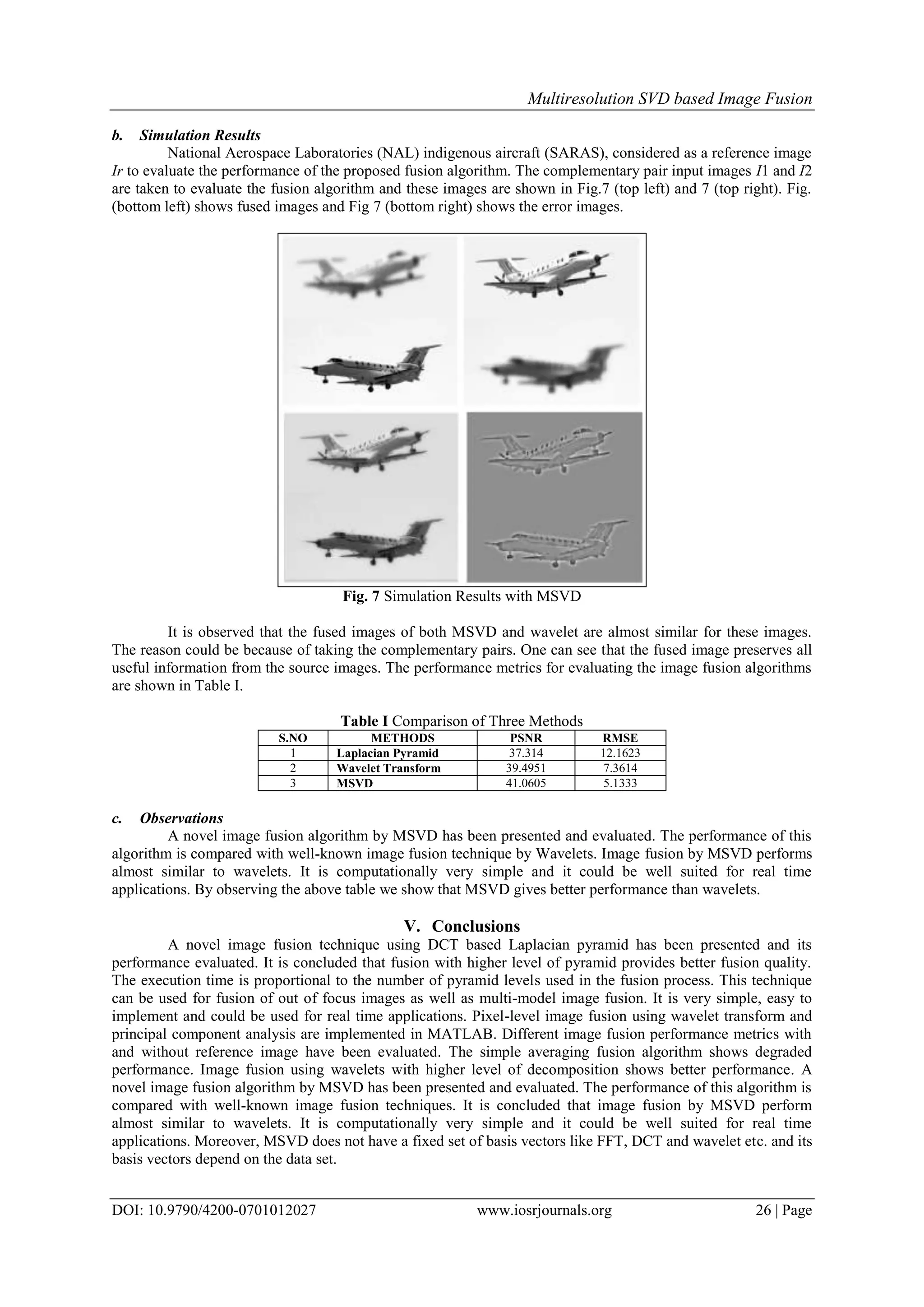
The document discusses multiresolution image fusion techniques using singular value decomposition (SVD) in the context of remote sensing and imaging applications. It compares performance metrics of various image fusion methods, including Laplacian pyramid and wavelet techniques, highlighting that the SVD-based approach offers improved fusion quality. The study concludes that the proposed image fusion technique outperforms existing methods in terms of objective quality assessment metrics.
![IOSR Journal of VLSI and Signal Processing (IOSR-JVSP)
Volume 7, Issue 1, Ver. I (Jan. - Feb. 2017), PP 20-27
e-ISSN: 2319 – 4200, p-ISSN No. : 2319 – 4197
www.iosrjournals.org
DOI: 10.9790/4200-0701012027 www.iosrjournals.org 20 | Page
Multiresolution SVD based Image Fusion
Dr. G.A.E. Satish Kumar1
, Jaya Krishna Sunkara2
1
Professor, Department of ECE, Vardhaman College of Engineering (Autonomous), Hyderabad, INDIA
2
PG Scholar, Department of ECE, Sri Venkateswara University College of Engineering, Tirupati, INDIA
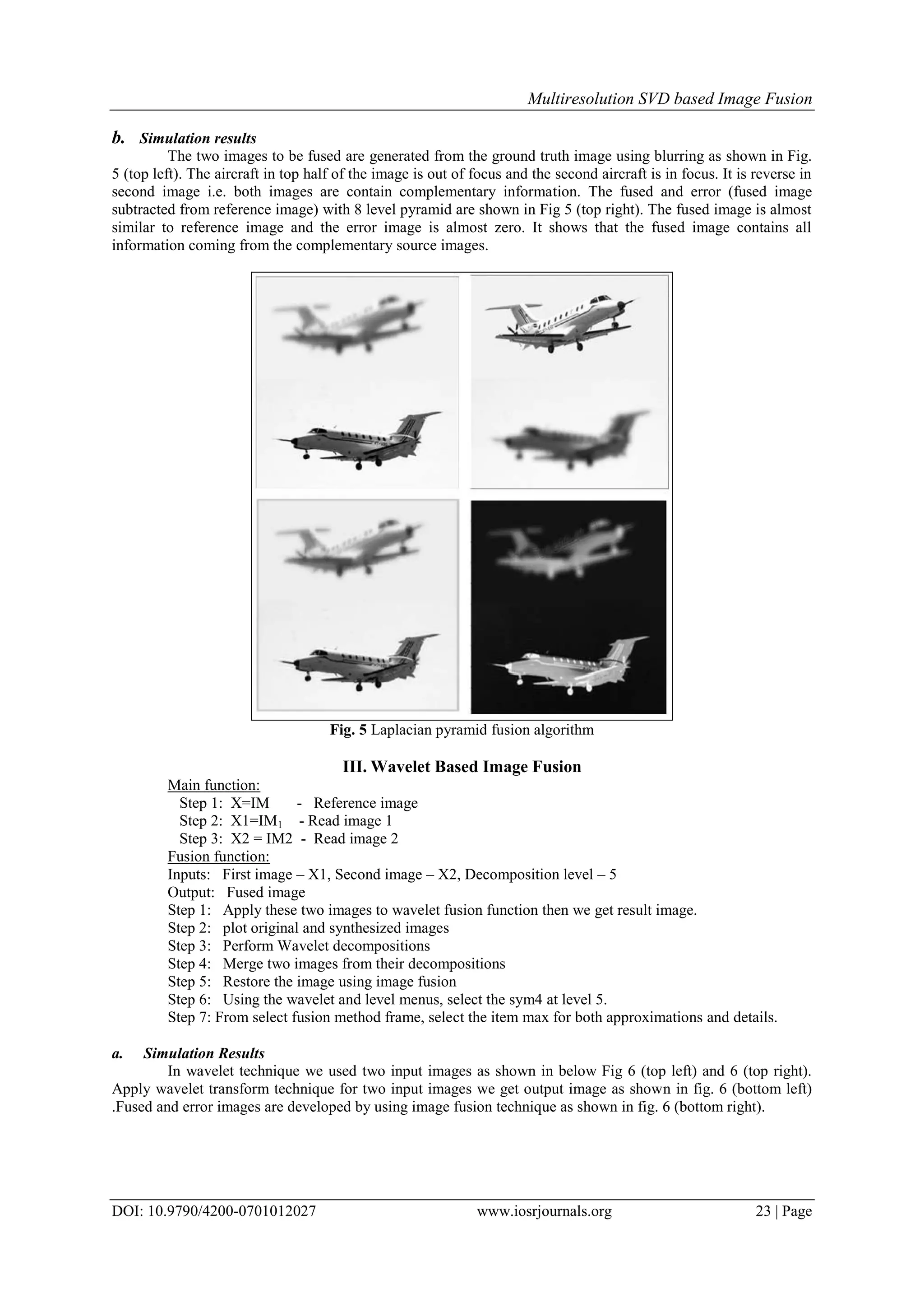
Abstract: Image fusion is the process of combining two or more images with specific objects with more
precision. It is very common that when one object is focused remaining objects will be less highlighted. To get
an image highlighted in all areas, a different means is necessary. This is done by the Image Fusion. In remote
sensing, the increasing availability of Space borne images and synthetic aperture radar images gives a
motivation to different kinds of image fusion algorithms. In the literature a number of time domain image fusion
techniques are available. Few transform domain fusion techniques are proposed. In transform domain fusion
techniques, the source images will be decomposed, then integrated into a single data and will be reconstructed
back into time domain. In this paper, singular value decomposition as a tool to have transform domain data will
be utilized for image fusion. In the literature, the quality assessment of fusion techniques is mainly by subjective
tests. In this paper, objective quality assessment metrics are calculated for existing and proposed techniques. It
has been found that the new image fusion technique outperformed the existing ones.
Keywords: Image fusion, Laplacian Pyramid, SVD, Wavelet.
I. Introduction
Extracting more information from multi-source images is a gorgeous thing in remotely sensed image
processing, which is called data fusion. There are many image fusion methods such as WS, PCA, WT, GLP etc.
Among these methods WT and GLP methods can preserve more image spectral characteristics than the others.
So here we adopt – wavelet method [1][2][3].
Fig. 1 Image Fusion
With the recent rapid developments in the field of sensor technologies multi-sensor systems have
become a certainty in a growing number of fields such as remote sensing, medical imaging, machine vision and
the military applications for which they were first developed [2]. Image fusion provides an effective way of
reducing this increasing volume of information while at the same time mining all the useful information from
the source images.Multi-sensor data often presents complementary information about the region charted, so
image fusion delivers an effective method to enable comparison and analysis of such data. The role of image
fusion apart from recognition is in applications such as remote sensing and medical imaging [4][5][6]. For
example, visible-band and infrared images may be fused to aid pilots landing aircraft in poor visibility. Multi-
sensor images often have different geometric representations, which have to be transformed to a common
representation for fusion. Multi-sensor registration is also affected by the differences in the sensor images.
However, image fusion does not necessarily imply multi-sensor sources, there are interesting applications for
both single-sensor and multi-sensor image fusion system [7][8].
a. Single Sensor Image Fusion System
An illustration of a single sensor image fusion system is shown in Figure .The sensor shown could be a
visible-band sensor such as a digital camera. This sensor captures the real world as a sequence of images [9].
The sequence is then fused in one single image and used either by a human operator or by a computer to do
some task. For example in object detection, a human operator searches the scene to detect objects such intruders
in a security area [10][11][12].](https://image.slidesharecdn.com/d0701012027-170711060124/75/Multiresolution-SVD-based-Image-Fusion-1-2048.jpg)
![Multiresolution SVD based Image Fusion
DOI: 10.9790/4200-0701012027 www.iosrjournals.org 21 | Page
Fig. 2 Single-Sensor Image Fusion System
This kind of systems has some limitations due to the capability of the imaging sensor that is being used.
The conditions under which the system can operate, the dynamic range, resolution, etc. are all limited by the
capability of the sensor. For example, a visible-band sensor such as the digital camera is appropriate for a
brightly illuminated environment such as daylight scenes but is not suitable for poorly illuminated situations
found during night, or under adverse conditions such as in fog or rain [13].
b. Multi-Sensor Image Fusion System
Multi-sensor image fusion systems overcomes the limitations of a single sensor vision system by
combining the images from these sensors to form a composite image Multiple images of same scene will be
taken by two or more capturing devices and then be fused. It is sufficient to each capturing device to capture one
image with better focus on one possible object. All the objects in the scene will be focused well, because of
more capturing devices. The multi-sensor image fusion system is more efficient comparing to the single sensor
image fusion system [14]. The multi sensor image fusion system is more accurate. The multi sensor image
fusion system is shown in below figure. The multi sensor image fusion system is more robust and gives accurate
results. Finally by comparing both single sensor image fusion system and multi sensor image system, the multi
sensor image fusion system has more advantages.
c. Performance Evaluation
The performance of image fusion algorithms can be evaluated when the reference image is available.
Here two performance metrics are considered. They are Peak signal to noise ratio (PSNR) and Root mean
square error(RMSR)
M
x
N
y
fr
yxyx
MN
PSNR
II
L
1 1
2
2
10
)),(),((
1
20log
Fig. 3 Multi Sensor Image Fusion System
where, L in the number of gray levels in the image This value will be high when the fused and reference images
are alike and higher value implies better fusion.
RMSE=
M
x
N
y
fr
yxyx
MN II1 1
2
)),(),((
1
It is computed as the root mean square error (RMSE) of the corresponding pixels in the reference
image Ir and the fused image If. It will be nearly zero when the reference and fuse images are alike and it will
increase when the dissimilarity increases [15].](https://image.slidesharecdn.com/d0701012027-170711060124/75/Multiresolution-SVD-based-Image-Fusion-2-2048.jpg)
![Multiresolution SVD based Image Fusion
DOI: 10.9790/4200-0701012027 www.iosrjournals.org 22 | Page
II. Laplacian Pyramid based Image Fusion
This work focuses on both these requirements and proposes a method that integrates the Laplacian
pyramid algorithm, wavelets and spatial frequency. Although the fusion can be performed with more than two
input images, this study considers only two input images. The algorithm decomposes the input image using 2D-
DWT. The lower approximations are subjected to Laplacian pyramid algorithm. The SF algorithm combined
with wavelet fusion algorithm is used for higher approximations. The new sets of detailed and approximate
coefficients from each image are then added to get the new fused coefficients.
The final step performs Inverse DWT with the new coefficients to construct the fused image. The two
main components of the proposed algorithm are the Laplacian Pyramid algorithm and the wavelet algorithm and
are explained in the following sub-sections. The Laplacian Pyramid [6] implements a ―pattern selective
approach to image fusion, so that the composite image is constructed not a pixel at a time, but a feature at a
time. The basic idea is to perform a pyramid decomposition on each source image, then integrate all these
decompositions to form a composite representation, and finally reconstruct the fused image by performing an
inverse pyramid transform [16].
The first step is to construct a pyramid for each source image. The fusion is then implemented for each
level of the pyramid using a feature selection decision mechanism. The feature selection method selects the most
salient pattern from the source and copies it to the composite pyramid, while discarding the least significant
salient pattern. In order to eliminate isolated points after fusion, a consistency filter is applied.
FN(X,Y) =
2
),(),( YXBYXA NN
Fig. 4 Laplacian pyramid fusion algorithm
a. Laplacian algorithm
Main Function:
Step 1: IM Read reference image.
IM1 Read the first image.
IM2 Read the second image.
Step 2: Apply the two input images to the fusion function which gives the resultant image.
Step 3: Calculate MSE and PSNR between the reference and resulting image.
Fusion Function:
Inputs: First image – IM1, Second image – IM2, Pyramid Levels – 2.
Output: Fused image.
Step 1: for i=1 to k
Step 2: IM reduced version of IM1 using DCT
Step 3: TEMP expanded version of IM using DCT
Step 4: Id1 IM1 – TEMP
Step 5: IM1 IM
Step 6: Repeat steps 2 to 5 for image 2.
Step 7: B [(Id1-Id2)≥0]
Step 8: Idf(i) Image with pixels from Id1 or Id2 whichever is high.
Step 9: end for
Step 10: imf = ½ (IM1 + IM2)
Step 11: for i=k to 1
Step 12: imf = Idf(i) + expand(imf)
Step 13: end for
Reduce Function:
Input: Image – I
Output: Reduced image – Ir
Step 1: mn size(I)/2
Step 2: II dct(I)
Step 3: Iridct(II, 1 to mn, 1 to mn)](https://image.slidesharecdn.com/d0701012027-170711060124/75/Multiresolution-SVD-based-Image-Fusion-3-2048.jpg)
![Multiresolution SVD based Image Fusion
DOI: 10.9790/4200-0701012027 www.iosrjournals.org 24 | Page
Fig. 6 Screenshots of Image Fusion with wavelets
In comparison table in next section compare the design metrics of laplacian pyramid and wavelet
transform technique. Wavelet transform gives high PSNR value 39.4951 and low RMSE value 7.3614.compare
to laplacian pyramid wavelet gives better result. The performance metrics for evaluating the image fusion
algorithms are shown in Table.
b. Observations
In this wavelet technique we observe both techniques are same but design metrics different. Laplacian
gives low PSNR value 37.3154 and high RMSE value 12.1623 compare to wavelet transform. Wavelet
transform gives high PSNR 39.4951 and low RSME 7.3614 .wavelet gives better result compare to laplacian.
IV. Multiresolution SVD
Multi-resolution singular value decomposition is very similar to wavelets transform, where signal is
filtered separately by low pass and high pass finite impulse response (FIR) filters and the output of each filter is
decimated by a factor of two to achieve first level of decomposition. The decimated low pass filtered output is
filtered separately by low pass and high pass filter followed by decimation by a factor of two provides second
level of decomposition.
)()4()2(
)1()3()1(
1
Nxxx
Nxxx
X
Denote the scatter matrix T1=X1X1
T
and let u1 be the Eigen vector matrix that brings T1 into diagonal
metrics. Let X = [x(1), x(2),..., x(N)] represent a 1D signal of length N and it is assumed that N is divisible by 2K
for K ≥1 21-26. Rearrange the samples in such a way that the top row contains the odd number indexed samples
and the bottom row contains the even number indexed samples. Let the resultant matrix called data matrix is:
The diagonal matrix
2
2
2
12
1
)1(0
0)1(
S
S
S
contains the square of the singular values, with S1(1)>S2(2).Let X1=U1
T
X1 so that X1=U1X1.The top row of 1 ˆX
, denoted 1 ˆX(1,:) contains approximation component that corresponds to the largest eigenvalue. The bottom
row of 1 ˆX, denoted 1 Xˆ(2,:) contains detail component that corresponds to the smallest eigenvalue. Let 1 1 Φ
= Xˆ (1,:) and 1 1 Ψ = Xˆ (2,:) represent the approximation and detail components respectively. The successive
levels of decomposition repeats the procedure described above by placing the approximation component Φ1 in
place of X. The above outlined procedure can be described formally. This procedure can be repeated recursively
K times. Let Φ0(1,:) = X so that the initial approximation component is the original signal. For each level l, the
approximation component vector Φl has l l N = N / 2 elements that are represented as:
The K-level MSVD for l=1,2,......k-1 as follows:
)2()4()2(
)2()3()1(
111
1111
llll
llll
l
N
N
X
](https://image.slidesharecdn.com/d0701012027-170711060124/75/Multiresolution-SVD-based-Image-Fusion-5-2048.jpg)
![Multiresolution SVD based Image Fusion
DOI: 10.9790/4200-0701012027 www.iosrjournals.org 25 | Page
T1=XlXl
T
=UlSl
2
Ul
T
, where singular values to be changed as Sl(l) >Sl(2). Xl = Ul
T
X1 :),1(ll X and
:),2(ll X . In general, it is sufficient to store the lowest resolution approximation component vector ΦL , the
details component vectors Ψl for l =1,2,...,L and the eigenvector matrices Ul for =1,2,..., L . Hence the MSVD
can be written as: 2
11
2
1
)(,,
lllL UX . The original signal X can be reconstructed from the right hand side,
since the steps are reversible. 1D multi-resolution singular value decomposition (MSVD) can be easily extended
to 2D MSVD and even for higher dimensions. The first level decomposition of the image proceeds as follows.
Divide the M × N image X into non-overlapping 2× 2 blocks and arrange each block into a 4×1 vector by
stacking columns to form the data matrix X1.
The blocks may be taken in transpose raster scan manner or in other words proceeding downwards first
and then to right. The Eigen-decomposition of the 4× 4 scatter matrix is: T 2 T 1 1 1 1 1 1 T =X X =U S U (12)
where the singular values are arranged in decreasing order as s1(1) ≥ s2 (2) ≥ s3 (3) ≥ s4 (4) Let T 1 1 1 Xˆ =U
X . The first row of 1 Xˆ corresponds to the largest eigenvalue and considered as approximation component. The
remaining rows contain the detail component that may correspond to edges or texture in an image. The elements
in each row may be rearranged to form M / 2×N / 2 matrix.
Before proceeding to next level of decomposition, let Φ1 denote M / 2×N / 2matrix formed by
rearranging the row 1 ˆX(1,:) into matrix by first filling in the columns and then rows. Similarly, each of the
three rows 1 Xˆ (2,:) , 1 Xˆ ( 3,:) and 1 Xˆ (4,:)may be arranged into M / 2×N / 2matrices that are denoted as 1 ΨV
, 1 ΨH and 1 ΨD respectively. The next level of decomposition proceeds as above where X is replaced by Φ1.
The complete L level decompositions may be represented as: L
l
L
l
DHV
L UX 111111 ,,,,
The original image X can be reconstructed from the right hand side, since the steps are reversible.
a. Algorithm
Main Function:
Step 1: IM Read reference image.
IM1 Read the first image.
IM2 Read the second image.
Step 2: Apply the two input images to the fusion function which gives the resultant image.
Step 3: [X1, U1] MSVD(IM1)
Step 4: [X2, U2] MSVD(IM2)
Step 5: Prepare LL, LH, HL and HH components (of an image say X) from the
corresponding parts of the images X1 and X2 by using the following rule.
i) For LL component take average of that of X1 and X2.
ii) For the remaining components take from X1 or X2 whichever is high.
Step 6: U ½ (U1 + U2)
Step 7: imf IMSVD(X, U)
Step 8: Calculate RMSE and PSNR between the reference and resulting image.
MSVD Function:
Input: Image – x
Outputs:MSVD coefficients – Y, Unitary matrix (U in SVD)
Step 1: m, n size(x)/2
Step 2: A Zero matrix of order 4xm*n
Step 3: A x (reshape x into the format of x)
Step 4: [U,S] svd(x)
Step 5: T U*A
Step 6: Y.LL First row of T (reshaped into mxn matrix)
Y.LH Second row of T (reshaped into mxn matrix)
Y.HL Third row of T (reshaped into mxn matrix)
Y.HH Fourth row of T (reshaped into mxn matrix)
IMSVD Function:
Inputs: MSVD coefficients – Y, Unitary matrix (U in SVD)
Output: Fused Image – X
Step 1: m, n size(Y.LL)
Step 2: mn m*n
Step 3: T Zero matrix of order 4xm*n
Step 4: T Y (each of four components as rows, so that T is a matrix of order 4xm*n)
Step 5: A U*T
Step 6: X Zero matrix of order 2mx2n
Step 7: X A (by reshape)](https://image.slidesharecdn.com/d0701012027-170711060124/75/Multiresolution-SVD-based-Image-Fusion-6-2048.jpg)
![Multiresolution SVD based Image Fusion
DOI: 10.9790/4200-0701012027 www.iosrjournals.org 27 | Page
References
[1] Pajares, Gonzalo & Manuel, Jesus de la Cruz, A wavelet based image fusion tutorial, Pattern Recognition, 37, 1855-872, 2007.
[2] Varsheny, P.K., Multi-sensor data fusion, Elec. Comm. Engg., Journal, 9(12), 245-53, 1997.
[3] Burt, P.J. & Lolczynski, R.J. Enhanced image capture through fusion, Proc. of 4th International Conference on Computer Vision,
Berlin, Germany, 173-82, 1993.
[4] Mallet, S.G. A theory for multiresolution signal decomposition: The wavelet representation. IEEE Trans. Pattern Anal. Mach.
Intel., 11(7), 674-93, 1989.
[5] Wang, H.; Peng, J. & W. Wu. Fusion algorithm for multi-sensor image based on discrete multiwavelet transform, IEEE Pro. Vis.
Image Signal Process, 149(5), 2002.
[6] Li, H.; Manjunath, B.S. & Mitra, S.K. Multisensor image fusion using wavelet transform, Graph models image process, 5, 57(3),
235-45, 2005.
[7] Pu. T. & Ni, G. Contrast-based image fusion using discrete wavelet transform. Optical Engineering, 39(8), 2075-2082, 2000.
[8] Yocky, D.A. Image merging and data fusion by means of the discrete two-dimensional wavelet transform. J. Opt. Soc. Am. A, 12(9),
1834-841, 1995.
[9] Nunez, J.; Otazu, X.; Fors, O.; Prades, A.; Pala, V. & Arbiol, R. Image fusion with additive multiresolution wavelet decomposition:
applications to spot1 landsat images. J. Opt. Soc. Am. A, 16, 467-74, 1999.
[10] Rockinger, O. Image sequence fusion using a shift invariant wavelet transform. Proceedings of IEEE Int. Conf. on Image
Processing, 13, 288-91, 1997.
[11] Qu, G.H.; Zang, D.L. & Yan P.F. Medical image fusion by wavelet transform modulus maxima. J. of the Opt. Soc. Of America, 9,
184-90, 2001.
[12] Chipman, L.J.; Orr, T.M. & Graham, L.N. Wavelets and Image fusion. Proceedings SPIE, 2529, 208-19, 1995.
[13] Jahard, F.; Fish, D.A.; Rio, A.A. & Thompson, C.P. Far/near infrared adapted pyramid-based fusion for automotive night vision.
IEEE Proc. 6th Int. Conf. on Image Processing and its Applications (IPA97), 886-90, 1997.
[14] Ajazzi, B.; Alparone, L.; Baronti, S. & Carla, R. Assessment pyramid-based multisensor image data fusion. Proceedings SPIE,
3500, 237-48, 1998.
[15] Akerman, A. Pyramid techniques for multisensory fusion. Proc. SPIE, 2828, 124-31, 1992.
[16] Toet, A.; Van Ruyven, L.J. & Valeton, J.M. Merging thermal and visual images by a contrast pyramid. Optical Engineering, 28(7),
789-92, 1989.](https://image.slidesharecdn.com/d0701012027-170711060124/75/Multiresolution-SVD-based-Image-Fusion-8-2048.jpg)