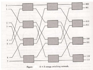
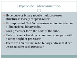
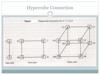
Introduction and Characteristics of Multiprocessor
Interconnection Structures
Inter Processor Arbitration
Inter Processor communication and synchronization
Cache Coherence
Multiprocessor
Introduction
 A multiprocessor system is an interconnection of two
or more CPUs with memory and I/O equipment.
 IOPs are generally not included in the definitions of
multiprocessor system unless they have
computational facilities comparable to CPUs.
 Multiprocessor are MIMD system.
 Multicomputer system includes number of
computers connected together by means of
communication lines.
 It improves reliability.
 If one system fails, the whole system continue to
function with perhaps low efficiency.
 The computation can proceed in parallel in two
ways:
 Multiple independent jobs operate in parallel
 A single job can be partitioned into multiple parallel tasks
 Multiprocessor are classified by the way their
memory is organized:
 Shared memory or tightly coupled microprocessor
 Distributed memory or loosely coupled microprocessor
Interconnection Structures
 The components that forms the multiprocessor
system are:
 CPUs
 IOPs
 I/O devices
 Memory
 Physical forms available for establishing an
interconnection network are:
 Time Shared Common Bus
 Multiport Memory
 Crossbar Switch
 Multistage switching network
 Hypercube System
Time Shared Common Bus
Multistage Switching Network
Hypercube Interconnection
 Hypercube or binary n-cube multiprocessor
structure is loosely coupled system.
 It composed of N=2^n processors interconnected in
n-dimensional binary cube.
 Each processor form the node of the cube.
 Each processor has direct communication path with
n other neighbor processor.
 There are 2^n distinct n-bit binary address that can
be assigned to each processor.
Hypercube Connection
Interprocessor Arbitration
 Computer system contain a number of buses at
various levels to facilitate the transfer of information.
 A bus that connects major components in a
multiprocessor system such as CPU, IOP and
memory, is called system bus.
 Arbitration logic is the part of system bus controller
placed between local bus and system bus that resolve
the multiple contention for shared resources.
System Bus
 A typical system consists of approximately 100 signal
lines.
 These lines are divided into three functional groups:
data, address and control.
 In addition there are power distribution lines that
supply power to the components.
 Example IEEE standard 796 multi bus system has 16
data lines, 24 address lines, 26 control lines and 20
power lines for total of 86 lines.
 Data lines provide a path for the transfer of data
between processor and common memory.
 The number of data lines are usually multiple of 8,
with 16 and 32 being most common.
 Address lines are used to indentify memory location
or any other source and destination units.
 The number of address lines determine the
maximum possible memory capacity in the system.
 The control lines provides signal for controlling
information transfer.
 Timing signals indicate validity of data and address.
 Command signal specify the operation to be
performed.
 Data transfer on the system can be
 Synchronous
 Asynchronous
Arbitration Procedure
 Arbitration procedure service all processor requests
on the basis of established priorities.
 It can be implemented in two ways:
 Serial Connection of Units
 Parallel Connection of Units
Serial Arbitration Procedure
 It is obtained from daisy chain connection of bus
arbitration circuit similar to the case of priority
interrupt.
 Each bus has its own arbiter logic which are
arranged according to the priorities from highest to
the lowest.
Parallel Arbitration Logic
 It uses an external priority encoder and decoder.
 Each bus arbiter has a bus request output lines and a
bus acknowledge input lines.
 Each arbiter enables request lines when its processor
is requesting the system bus.
 The one with highest priority determine by the
output of the decoder get access to the bus.
Dynamic Arbitration Algorithm
 Serial and parallel bus arbitration are static since the
priorities assigned is fixed.
 In dynamic arbitration priorities of the system
changes while the system is in operation.
 The various algorithms used are:
 Time Slice
 Polling
 Least Recently Used(LRU)
 First In First Out(FIFO)
 Rotating Daisy Chain
Inter processor Communication
 All the processors in the multi processor system need
to communicate with each other.
 The most common way is to set aside portion of
memory that is accessible to all processor.
 Sending processor puts the data and the address of
the receiving processor in the memory.
 All the processor periodically check the memory for
any information.
 If they find their address they read the data.
 This procedure is time consuming.
 Another procedure is to send the interrupt signal to
the receiving processor whenever the sending
processor leaves the message.
 In addition to shared memory, multiprocessor
system may have other shared resources.
 To prevent the conflicting use of shared resources by
several processor there must be provision for
assigning resources to processor.
 This task is handled by the Operating System.
 There are three organization that have been used in
design of OS of multiprocessor:
 Master-Slave Configuration
 Separate OS
 Distributed OS
 In master slave configuration, one processor
designated as master execute OS function. If slave
processor need OS service, it must request to the
master processor.
 In separate OS configuration, each processor can
execute the OS routine it needed.
 This organization is suited for loosely coupled system
where every processor have its own copy of the entire
OS.
 In distributed OS, the OS routines are distributed
among the processor.
 Each particular OS function is assigned to only one
processor at a time.
 Since the routines float from one processor to
another it is also called floating OS.
Inter processor Synchronization
 Synchronization is special case of communication
where data used to communicate between processor
is control information.
 It is needed to enforce correct sequence of process
and to ensure mutually exclusive access to shared
writable data.
 A number of hardware mechanisms for mutual
exclusion have been developed. One of the most
popular is through the use of binary semaphore.
Mutual Exclusion with Semaphore
 Proper functioning multi-processor should
guarantee orderly access to shared resources. So that
data can not be changed simultaneously by two
processor.
 This is called mutual exclusion.
 Mutual exclusion must be provided in multi
processor to enable one processor to lock out access
to shared resources once it entered in critical section.
 Critical section is a program sequence, that must be
completed once begun.
 Binary variable semaphore is used to indicate
whether the processor is in critical section.
 Semaphore is software controlled flag stored in
common memory.
 If it is 1, processor is executing critical section. If it is
0, it indicate memory is available for the other
processor.
 Testing and setting semaphore is itself a critical task
and must be performed in single indivisible task.
 A semaphore can be initialized by means of test and
set instruction in conjunction with a hardware lock
mechanism.
 A hardware lock is processor generated signal that
prevent other processor from using system bus as
long as signal is active.
 Test and set instruction test and set semaphore and
activate lock mechanism during the time that it is
testing and setting it.
 The last instruction in the program must be clear
location SEM to 0 to released shared resource to
other processor.
 Lock signal must be active during execution of test
and set instruction.
 It does not have to be active once semaphore is set.
Cache Coherence
 In shared memory multi-processor system, processor
share memory and they have local memory(part or
all of which is cache).
 To ensure ability of the system to execute memory
instruction independently, multiple copies of the
data must be identical which is called cache
coherence.
Condition to Incoherence
 This condition arise when the processor need to
share the writable data.
 In both policy write back and write through
incoherence condition is created.
 In case of DMA also, IOP modify the data in main
memory which reside in the cache and can’t be
updated.
Solution using Software
 A simple way is to disallow to have private cache and
use the common memory for shared resources.
 Another way is to cache only the read only data in
the local cache and use the common memory for
writable data.
 A scheme that allow writable data to reside in at least
in one cache is the use of centralized global table.
 In this table status of each memory block as read
only(RO) or read write(RW) is stored.
 All local cache can store RO memory blocks.
 RW memory blocks are stored only one cache that is
shared by all.
Hardware Solution
 Snoopy cache controller is a hardware specially
designed to watch the system bus for write
operation.
 When a word is updated in cache, main memory is
also updated.
 Local snoopy controller watch the cache if they have
the address updated.
 If the copy exist, it is marked invalid.
 If CPU request the same address, it is fetch from the
main memory and updated in cache.

Multiprocessor

  • 1.
    Introduction and Characteristicsof Multiprocessor Interconnection Structures Inter Processor Arbitration Inter Processor communication and synchronization Cache Coherence Multiprocessor
  • 2.
    Introduction  A multiprocessorsystem is an interconnection of two or more CPUs with memory and I/O equipment.  IOPs are generally not included in the definitions of multiprocessor system unless they have computational facilities comparable to CPUs.  Multiprocessor are MIMD system.  Multicomputer system includes number of computers connected together by means of communication lines.
  • 3.
     It improvesreliability.  If one system fails, the whole system continue to function with perhaps low efficiency.  The computation can proceed in parallel in two ways:  Multiple independent jobs operate in parallel  A single job can be partitioned into multiple parallel tasks
  • 4.
     Multiprocessor areclassified by the way their memory is organized:  Shared memory or tightly coupled microprocessor  Distributed memory or loosely coupled microprocessor
  • 5.
    Interconnection Structures  Thecomponents that forms the multiprocessor system are:  CPUs  IOPs  I/O devices  Memory  Physical forms available for establishing an interconnection network are:  Time Shared Common Bus  Multiport Memory
  • 6.
     Crossbar Switch Multistage switching network  Hypercube System
  • 7.
  • 12.
  • 15.
    Hypercube Interconnection  Hypercubeor binary n-cube multiprocessor structure is loosely coupled system.  It composed of N=2^n processors interconnected in n-dimensional binary cube.  Each processor form the node of the cube.  Each processor has direct communication path with n other neighbor processor.  There are 2^n distinct n-bit binary address that can be assigned to each processor.
  • 16.
  • 17.
    Interprocessor Arbitration  Computersystem contain a number of buses at various levels to facilitate the transfer of information.  A bus that connects major components in a multiprocessor system such as CPU, IOP and memory, is called system bus.  Arbitration logic is the part of system bus controller placed between local bus and system bus that resolve the multiple contention for shared resources.
  • 18.
    System Bus  Atypical system consists of approximately 100 signal lines.  These lines are divided into three functional groups: data, address and control.  In addition there are power distribution lines that supply power to the components.  Example IEEE standard 796 multi bus system has 16 data lines, 24 address lines, 26 control lines and 20 power lines for total of 86 lines.
  • 19.
     Data linesprovide a path for the transfer of data between processor and common memory.  The number of data lines are usually multiple of 8, with 16 and 32 being most common.  Address lines are used to indentify memory location or any other source and destination units.  The number of address lines determine the maximum possible memory capacity in the system.  The control lines provides signal for controlling information transfer.
  • 20.
     Timing signalsindicate validity of data and address.  Command signal specify the operation to be performed.  Data transfer on the system can be  Synchronous  Asynchronous
  • 22.
    Arbitration Procedure  Arbitrationprocedure service all processor requests on the basis of established priorities.  It can be implemented in two ways:  Serial Connection of Units  Parallel Connection of Units
  • 23.
    Serial Arbitration Procedure It is obtained from daisy chain connection of bus arbitration circuit similar to the case of priority interrupt.  Each bus has its own arbiter logic which are arranged according to the priorities from highest to the lowest.
  • 25.
    Parallel Arbitration Logic It uses an external priority encoder and decoder.  Each bus arbiter has a bus request output lines and a bus acknowledge input lines.  Each arbiter enables request lines when its processor is requesting the system bus.  The one with highest priority determine by the output of the decoder get access to the bus.
  • 27.
    Dynamic Arbitration Algorithm Serial and parallel bus arbitration are static since the priorities assigned is fixed.  In dynamic arbitration priorities of the system changes while the system is in operation.  The various algorithms used are:  Time Slice  Polling  Least Recently Used(LRU)  First In First Out(FIFO)  Rotating Daisy Chain
  • 28.
    Inter processor Communication All the processors in the multi processor system need to communicate with each other.  The most common way is to set aside portion of memory that is accessible to all processor.  Sending processor puts the data and the address of the receiving processor in the memory.  All the processor periodically check the memory for any information.  If they find their address they read the data.  This procedure is time consuming.
  • 29.
     Another procedureis to send the interrupt signal to the receiving processor whenever the sending processor leaves the message.  In addition to shared memory, multiprocessor system may have other shared resources.  To prevent the conflicting use of shared resources by several processor there must be provision for assigning resources to processor.  This task is handled by the Operating System.
  • 30.
     There arethree organization that have been used in design of OS of multiprocessor:  Master-Slave Configuration  Separate OS  Distributed OS  In master slave configuration, one processor designated as master execute OS function. If slave processor need OS service, it must request to the master processor.
  • 31.
     In separateOS configuration, each processor can execute the OS routine it needed.  This organization is suited for loosely coupled system where every processor have its own copy of the entire OS.  In distributed OS, the OS routines are distributed among the processor.  Each particular OS function is assigned to only one processor at a time.  Since the routines float from one processor to another it is also called floating OS.
  • 32.
    Inter processor Synchronization Synchronization is special case of communication where data used to communicate between processor is control information.  It is needed to enforce correct sequence of process and to ensure mutually exclusive access to shared writable data.  A number of hardware mechanisms for mutual exclusion have been developed. One of the most popular is through the use of binary semaphore.
  • 33.
    Mutual Exclusion withSemaphore  Proper functioning multi-processor should guarantee orderly access to shared resources. So that data can not be changed simultaneously by two processor.  This is called mutual exclusion.  Mutual exclusion must be provided in multi processor to enable one processor to lock out access to shared resources once it entered in critical section.  Critical section is a program sequence, that must be completed once begun.
  • 34.
     Binary variablesemaphore is used to indicate whether the processor is in critical section.  Semaphore is software controlled flag stored in common memory.  If it is 1, processor is executing critical section. If it is 0, it indicate memory is available for the other processor.  Testing and setting semaphore is itself a critical task and must be performed in single indivisible task.
  • 35.
     A semaphorecan be initialized by means of test and set instruction in conjunction with a hardware lock mechanism.  A hardware lock is processor generated signal that prevent other processor from using system bus as long as signal is active.  Test and set instruction test and set semaphore and activate lock mechanism during the time that it is testing and setting it.
  • 37.
     The lastinstruction in the program must be clear location SEM to 0 to released shared resource to other processor.  Lock signal must be active during execution of test and set instruction.  It does not have to be active once semaphore is set.
  • 38.
    Cache Coherence  Inshared memory multi-processor system, processor share memory and they have local memory(part or all of which is cache).  To ensure ability of the system to execute memory instruction independently, multiple copies of the data must be identical which is called cache coherence.
  • 39.
    Condition to Incoherence This condition arise when the processor need to share the writable data.  In both policy write back and write through incoherence condition is created.  In case of DMA also, IOP modify the data in main memory which reside in the cache and can’t be updated.
  • 43.
    Solution using Software A simple way is to disallow to have private cache and use the common memory for shared resources.  Another way is to cache only the read only data in the local cache and use the common memory for writable data.  A scheme that allow writable data to reside in at least in one cache is the use of centralized global table.  In this table status of each memory block as read only(RO) or read write(RW) is stored.
  • 44.
     All localcache can store RO memory blocks.  RW memory blocks are stored only one cache that is shared by all.
  • 45.
    Hardware Solution  Snoopycache controller is a hardware specially designed to watch the system bus for write operation.  When a word is updated in cache, main memory is also updated.  Local snoopy controller watch the cache if they have the address updated.  If the copy exist, it is marked invalid.  If CPU request the same address, it is fetch from the main memory and updated in cache.