The document discusses the 8085 microprocessor instruction set and addressing modes. It contains the following key points:
1) The 8085 has 74 instructions that are grouped into 5 categories - data transfer, arithmetic, logical, branch, and machine control operations. Most instructions have multiple formats.
2) Instructions are 1, 2, or 3 bytes in size depending on the operands. The opcode specifies the operation and registers while the operands provide data or addresses.
3) There are 5 addressing modes including register, immediate, direct, indirect, and implied that specify how operands are addressed in memory.
4) A sample program is provided to add two numbers and display the result using MVI, ADD, and
The document discusses the various instruction groups and addressing modes supported by the 8085 microprocessor. It describes 5 groups of instructions - data transfer, arithmetic, logical, branch/control, and stack/I/O. It also explains the 5 addressing modes - register, immediate, direct, indirect and implicit. For each addressing mode, it provides examples of instructions and explains their operation, machine cycles, and effect on flags. It also provides examples of 8085 assembly language programs using different instructions and addressing modes.
The document discusses microprocessors and the 8085 microprocessor. It provides details on:
1) The internal architecture and components of microprocessors and the 8085 microprocessor.
2) The different types of operations microprocessors can perform including internal data operations, microprocessor initiated operations, and peripheral initiated operations.
3) The addressing modes, instruction set, registers, and instruction types/formats of the 8085 microprocessor.
The document discusses Microprocessor and its Applications. It contains 28 questions related to microprocessors, their basic units, addressing modes, interrupts, assembly language instructions, and more. Specifically, it discusses the 8085 and 8051 microcontrollers, explaining concepts like multiplexing, flags, machine cycles, timing diagrams, and memory mapping.
1. The document discusses basic programming of the 8085 microprocessor. It covers the different types of programming languages including machine language, assembly language, and high-level languages.
2. The 8085 instruction set is classified into different groups like data transfer, arithmetic, logical, branch, and machine control instructions. Common instructions like MOV, ADD, SUB, and CALL are described.
3. The document provides examples of 8085 programs and instructions to load data, perform arithmetic operations, manage the stack, handle I/O, and control program flow. It also discusses assembler format and use of registers like the accumulator, flag register, and stack pointer.
The document defines timing diagrams, machine cycles, and T-states. It then discusses the specific machine cycles of the 8085 microprocessor, including the opcode fetch cycle, memory read/write cycles, I/O read/write cycles, and interrupt acknowledge cycle. It provides examples of timing diagrams for various instructions like STA, INR, and discusses registers and instructions like STAX, MVI, LHLD.
The 8085 microprocessor uses several addressing modes to specify the operands in instructions. These include implied, immediate, direct, register, and register indirect addressing modes. Implied addressing mode does not specify operands as they are implicit in the instruction. Immediate addressing mode embeds the operand in the instruction itself. Direct addressing directly specifies the memory location of the operand. Register addressing uses register operands. Register indirect addressing specifies the operand address using a register pair like the HL register.
The document provides an overview of microprocessors and microcontrollers. It discusses the basic concepts of microprocessors including the definition, components like the ALU, registers, control unit, memory and system bus. It describes how a microprocessor works and introduces machine language and 8085 assembly language. The later lectures discuss the internal architecture, registers, pin configuration and instruction set of the 8085 microprocessor. It also covers addressing modes, classification of instructions and use of the stack in 8085.
This document provides information about the 8085 and 8086 microprocessors. It begins with definitions of a microprocessor and details about the 8085 such as its power supply, clock frequency, and functions of the accumulator. It then discusses the 8085's registers, allowed register pairs, purpose of SID and SOD lines, and function of the IO/M signal. The document lists the categories of 8085 instructions and examples. It explains the differences between JMP and CALL instructions and shift and rotate instructions. Other topics covered include wait states, 8085 interrupts, its signal classification, operations performed on data, and the steps to fetch a byte. The document concludes with questions about the 8086's software aspects, multiprocessor
This document discusses the basics of microprocessors and the 8085 microprocessor. It begins with definitions of a microprocessor and its basic units. It then discusses multiplexing and how the 8085 demultiplexes address and data lines. It explains the functions of the IO/M, READY, HOLD and HLDA signals in the 8085. It defines flags and lists the flags in the 8085. It also defines terms like mnemonics, machine cycles, instruction cycles, fetch and execute cycles. It lists the machine cycles of the 8085 and explains the need for timing diagrams. It defines terms like T-state, opcode and operand. It discusses addressing modes in the 8085. It compares memory mapped I/
The document discusses microprocessors, their architecture, instructions, operations, interfacing and the 8085 and 8086 microprocessors. It provides details on the functional blocks, registers, addressing modes, procedures, calling conventions, and stack usage of the 8086 microprocessor. It also describes various assembler directives, operators, and concepts like logical segments, procedures, and passing parameters in registers vs memory for procedures.
The document discusses timing diagrams and machine cycles in the 8085 microprocessor. It provides details on the different machine cycles - opcode fetch, memory read, memory write, I/O read, and I/O write. It explains that the 8085 has a clock signal divided into T-states that represent portions of machine cycle operations. Examples are given of timing diagrams for instructions like MOV B,C, MVI B,43, and STA 526A to illustrate the sequence of events over multiple T-states.
The document provides an overview of the 8085 microprocessor programming model. It describes the hardware model including the ALU, accumulator, registers, buses, and flags. It also discusses the programming model, instruction set classification including data transfer, arithmetic, logical, and branching operations. Finally, it covers instruction word sizes, opcode format, and data formats like ASCII, BCD, signed and unsigned integers.
This document provides information about the 8-bit microprocessor unit REE602, including its instruction format, pin diagram, internal architecture, instruction types, and examples of instruction classification. It discusses the instruction format, one-byte, two-byte, and three-byte instructions. It also summarizes the pin diagram, internal architecture, timing diagrams, and provides examples of different types of instructions including data transfer, arithmetic, logical, and branching instructions.
The document provides information about the 8085 microprocessor. It begins with definitions of key terms like microprocessor, CPU, ALU, and bus. It then discusses the evolution of microprocessors from early 4-bit models to later 8-bit, 12-bit, and 16-bit models like the Intel 8085. The document details the architecture of the 8085, including its pin descriptions and addressing modes. It categorizes the instruction set into groups for data transfer, arithmetic, logical, branch, and machine control operations. Memory-mapped I/O is also introduced.
The document discusses the architecture of the 8085 microprocessor. It describes the various units that make up the 8085 architecture including the accumulator, arithmetic logic unit, general purpose registers, program counter, stack pointer, temporary register, flags, instruction register and decoder, timing and control unit, interrupt control, and serial I/O control. It provides details on each of these units and how they work together to allow the 8085 microprocessor to function.
The document summarizes addressing modes in microprocessors. It discusses:
- Three main types of addressing modes - stack-memory, data, and program-memory.
- Data addressing modes include immediate, direct, indirect, register, register indirect, implied, auto increment/decrement, relative, indexed, and base register.
- Direct addressing mode specifies the direct memory address of the operand. An example shows loading data from memory location 2805 to register A.
- Immediate addressing mode encodes the data directly in the instruction. An example shows moving the value 2550H into register AX.
- An example problem demonstrates calculating the effective address and operand value for direct and immediate modes.
This document discusses addressing modes and instruction sets for 8051 microcontrollers. It describes 5 addressing modes: immediate, direct, register direct, register indirect, and indexed addressing. It also outlines various instruction types like data transfer, arithmetic, logic, loop/jump, call, and flag instructions. Specific instructions and their machine cycle times are provided. Jump and call instructions like SJMP, LJMP, ACALL, and LCALL are explained along with examples. Finally, rotate instructions like RL, RLC, RR, and RRC are listed.
The document discusses the functional requirements and design of a central processing unit (CPU). It describes the main components that must be included in the CPU design such as an instruction fetch unit, operand fetch unit, register file, instruction register, instruction decoder, and arithmetic logic unit. It then provides details on the register file design for the Intel 8086 processor including the segment and pointer registers used for memory addressing. Finally, it outlines the six addressing modes used by the Intel 8086 for accessing data in memory.
The document discusses the addressing modes of the Intel 8085 microprocessor. It describes 5 addressing modes used: implied, immediate, direct, register, and register indirect. It provides examples of instructions that use each addressing mode. It also explains how data is transferred between memory and the microprocessor, involving the address bus, data bus, and control signals. Finally, it defines the 8085 programming model, which conceptualizes the registers and components involved in writing assembly language programs for the 8085.
This document discusses various addressing modes of the 8051 microcontroller. It begins by defining an addressing mode as the method of specifying the source and destination of operands in an instruction. It then lists the 8 addressing modes supported by the 8051: register, direct, indirect, immediate, relative, absolute, indexed, and long. Examples are provided for each mode. The document also compares microprocessors and microcontrollers, and discusses the differences between the 8085, 8086, and 8051 microchips. Finally, it poses questions about addressing modes and instruction types to continue the tutorial.
Computer Organization : CPU, Memory and I/O organizationAmrutaMehata
This document provides information on CPU, memory, and I/O organization. It begins with an overview of the main components of a computer including the processor unit, memory unit, and input/output unit. It then describes the CPU in more detail including the arithmetic logic unit, control unit, and CPU block diagram. The document discusses the system bus and its various lines. It also covers CPU registers, instruction cycles, and status and control flags. The document provides an overview of instruction set architecture and compares RISC and CISC processor designs.
The document provides information about microprocessors and the 8085 microprocessor. It defines key terms like microprocessor, ALU, registers, control unit, bus, machine cycle, T-state, instruction cycle, fetch cycle, execute cycle, flags, memory mapping, opcode fetch, interrupts, polling, and interrupt types. It describes the basic units and operations of a microprocessor, bus types, the instruction execution process, and interrupt handling. It also discusses I/O techniques, 8085 pins and signals, addressing modes, and differences between memory mapped and I/O mapped I/O.
The document describes the internal architecture and components of the 8085 microprocessor. It includes the following main units:
1) Processing unit containing the arithmetic logic unit (ALU), accumulator, flags register, and temporary register for performing arithmetic and logical operations.
2) Storage and interface unit containing registers like the general purpose registers, stack pointer, program counter, and address/data buffers for memory interfacing.
3) Instruction unit containing the instruction register, decoder and timing/control section for fetching and decoding instructions.
4) Interrupt and serial I/O unit for handling interrupts and serial communication with peripheral devices. The 8085 uses address, data and control buses to interface with external memory and devices.
The document describes an 8085 microprocessor system and trainer kit. It includes:
- An 8-bit 8085 microprocessor as the CPU.
- Up to 64KB of RAM and 8KB of EPROM memory.
- A 16-bit timer, 8255 I/O ports, and RS-232 interface.
- A keyboard, 7-segment LED display, and connectors for inputs/outputs.
Using recycled concrete aggregates (RCA) for pavements is crucial to achieving sustainability. Implementing RCA for new pavement can minimize carbon footprint, conserve natural resources, reduce harmful emissions, and lower life cycle costs. Compared to natural aggregate (NA), RCA pavement has fewer comprehensive studies and sustainability assessments.
KuberTENes Birthday Bash Guadalajara - K8sGPT first impressionsVictor Morales
K8sGPT is a tool that analyzes and diagnoses Kubernetes clusters. This presentation was used to share the requirements and dependencies to deploy K8sGPT in a local environment.
Understanding Inductive Bias in Machine LearningSUTEJAS
This presentation explores the concept of inductive bias in machine learning. It explains how algorithms come with built-in assumptions and preferences that guide the learning process. You'll learn about the different types of inductive bias and how they can impact the performance and generalizability of machine learning models.
The presentation also covers the positive and negative aspects of inductive bias, along with strategies for mitigating potential drawbacks. We'll explore examples of how bias manifests in algorithms like neural networks and decision trees.
By understanding inductive bias, you can gain valuable insights into how machine learning models work and make informed decisions when building and deploying them.
Batteries -Introduction – Types of Batteries – discharging and charging of battery - characteristics of battery –battery rating- various tests on battery- – Primary battery: silver button cell- Secondary battery :Ni-Cd battery-modern battery: lithium ion battery-maintenance of batteries-choices of batteries for electric vehicle applications.
Fuel Cells: Introduction- importance and classification of fuel cells - description, principle, components, applications of fuel cells: H2-O2 fuel cell, alkaline fuel cell, molten carbonate fuel cell and direct methanol fuel cells.
TIME DIVISION MULTIPLEXING TECHNIQUE FOR COMMUNICATION SYSTEMHODECEDSIET
Time Division Multiplexing (TDM) is a method of transmitting multiple signals over a single communication channel by dividing the signal into many segments, each having a very short duration of time. These time slots are then allocated to different data streams, allowing multiple signals to share the same transmission medium efficiently. TDM is widely used in telecommunications and data communication systems.
### How TDM Works
1. **Time Slots Allocation**: The core principle of TDM is to assign distinct time slots to each signal. During each time slot, the respective signal is transmitted, and then the process repeats cyclically. For example, if there are four signals to be transmitted, the TDM cycle will divide time into four slots, each assigned to one signal.
2. **Synchronization**: Synchronization is crucial in TDM systems to ensure that the signals are correctly aligned with their respective time slots. Both the transmitter and receiver must be synchronized to avoid any overlap or loss of data. This synchronization is typically maintained by a clock signal that ensures time slots are accurately aligned.
3. **Frame Structure**: TDM data is organized into frames, where each frame consists of a set of time slots. Each frame is repeated at regular intervals, ensuring continuous transmission of data streams. The frame structure helps in managing the data streams and maintaining the synchronization between the transmitter and receiver.
4. **Multiplexer and Demultiplexer**: At the transmitting end, a multiplexer combines multiple input signals into a single composite signal by assigning each signal to a specific time slot. At the receiving end, a demultiplexer separates the composite signal back into individual signals based on their respective time slots.
### Types of TDM
1. **Synchronous TDM**: In synchronous TDM, time slots are pre-assigned to each signal, regardless of whether the signal has data to transmit or not. This can lead to inefficiencies if some time slots remain empty due to the absence of data.
2. **Asynchronous TDM (or Statistical TDM)**: Asynchronous TDM addresses the inefficiencies of synchronous TDM by allocating time slots dynamically based on the presence of data. Time slots are assigned only when there is data to transmit, which optimizes the use of the communication channel.
### Applications of TDM
- **Telecommunications**: TDM is extensively used in telecommunication systems, such as in T1 and E1 lines, where multiple telephone calls are transmitted over a single line by assigning each call to a specific time slot.
- **Digital Audio and Video Broadcasting**: TDM is used in broadcasting systems to transmit multiple audio or video streams over a single channel, ensuring efficient use of bandwidth.
- **Computer Networks**: TDM is used in network protocols and systems to manage the transmission of data from multiple sources over a single network medium.
### Advantages of TDM
- **Efficient Use of Bandwidth**: TDM all
Embedded machine learning-based road conditions and driving behavior monitoringIJECEIAES
Car accident rates have increased in recent years, resulting in losses in human lives, properties, and other financial costs. An embedded machine learning-based system is developed to address this critical issue. The system can monitor road conditions, detect driving patterns, and identify aggressive driving behaviors. The system is based on neural networks trained on a comprehensive dataset of driving events, driving styles, and road conditions. The system effectively detects potential risks and helps mitigate the frequency and impact of accidents. The primary goal is to ensure the safety of drivers and vehicles. Collecting data involved gathering information on three key road events: normal street and normal drive, speed bumps, circular yellow speed bumps, and three aggressive driving actions: sudden start, sudden stop, and sudden entry. The gathered data is processed and analyzed using a machine learning system designed for limited power and memory devices. The developed system resulted in 91.9% accuracy, 93.6% precision, and 92% recall. The achieved inference time on an Arduino Nano 33 BLE Sense with a 32-bit CPU running at 64 MHz is 34 ms and requires 2.6 kB peak RAM and 139.9 kB program flash memory, making it suitable for resource-constrained embedded systems.
Using recycled concrete aggregates (RCA) for pavements is crucial to achieving sustainability. Implementing RCA for new pavement can minimize carbon footprint, conserve natural resources, reduce harmful emissions, and lower life cycle costs. Compared to natural aggregate (NA), RCA pavement has fewer comprehensive studies and sustainability assessments.
Recycled Concrete Aggregate in Construction Part II
MPMC UNIT-2.pdf
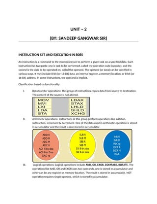
1. UNIT – 2
(BY: SANDEEP GANGWAR SIR)
INSTRUCTION SET AND EXECUTION IN 8085
An instruction is a command to the microprocessor to perform a given task on a specified data. Each
instruction has two parts: one is task to be performed, called the operation code (opcode), and the
second is the data to be operated on, called the operand. The operand (or data) can be specified in
various ways. It may include 8-bit (or 16-bit) data, an internal register, a memory location, or 8-bit (or
16-bit) address. In some instructions, the operand is implicit.
Classification based on functionality:
I. Data transfer operations: This group of instructions copies data from source to destination.
The content of the source is not altered.
II. Arithmetic operations: Instructions of this group perform operations like addition,
subtraction, increment & decrement. One of the data used in arithmetic operation is stored
in accumulator and the result is also stored in accumulator.
III. Logical operations: Logical operations include AND, OR, EXOR, COMPARE, ROTATE. The
operations like AND, OR and EXOR uses two operands, one is stored in accumulator and
other can be any register or memory location. The result is stored in accumulator. NOT
operation requires single operand, which is stored in accumulator.
2. IV. IV. Branching operations: Instructions in this group (JUMP, CALL, RETURN) can be used to
transfer program sequence from one memory location to another either conditionally or
unconditionally.
1. Jump Instructions – The jump instruction transfers the program sequence to the memory
address given in the operand based on the specified flag. Jump instructions are 2 types:
Unconditional Jump Instructions and Conditional Jump Instructions.
(a) Unconditional Jump Instructions: Transfers the program sequence to the described
memory address.
JMP address Jumps to the address Ex- JMP 2050
(b) Conditional Jump Instructions: Transfers the programs sequence to the described
memory address only if the condition in satisfied.
2. Call Instructions – The call instruction transfers the program sequence to the memory
address given in the operand. Before transferring, the address of the next instruction after
CALL is pushed onto the stack. Call instructions are 2 types: Unconditional Call Instructions
and Conditional Call Instructions.
(a) Unconditional Call Instructions: It transfers the program sequence to the memory
address given in the operand.
CALL address Unconditionally calls Ex - CALL 2050
(b) Unconditional Call Instructions: It transfers the program sequence to the memory
address given in the operand.
3. Return Instructions – The return instruction transfers the program sequence from the
subroutine to the calling program. Return instructions are 2 types: Unconditional Jump
Instructions and Conditional Jump Instructions.
3. (a) Unconditional Return Instruction: The program sequence is transferred unconditionally
from the subroutine to the calling program.
RET Return from the subroutine unconditionally Ex – RET
(b) Conditional Return Instruction: The program sequence is transferred unconditionally
from the subroutine to the calling program only is the condition is satisfied.
V. Machine control operations: Instruction in this group (HLT, EI, DI) control execution of other
instructions and control operations like interrupt, halt etc.
Classification based on length:
I. One-byte instructions: Instruction having one byte in machine code. (MOV B,C)
II. I. Two-byte instructions: Instruction having two byte in machine code. (MVI B,23H)
III. II. Three-byte instructions: Instruction having three byte in machine code. (LDA 1234H)
4. Addressing Modes
The process of specifying the data to be operated on by the instruction is called addressing. The various
formats for specifying operands are called addressing modes. The 8085 has the following five types of
addressing:
1. Immediate addressing
2. Direct addressing
3. Register direct addressing
4. Indirect addressing
5. Implicit addressing
Immediate Addressing:
5. In this mode, the operand given in the instruction - a byte or word – transfers to the destination register
or memory location.
Ex: MVI A, 9AH
The operand is a part of the instruction.
The operand is stored in the register mentioned in the instruction.
Direct addressing:
Memory direct addressing moves a byte or word between a memory location and register. The memory
location address is given in the instruction.
Ex: LDA 850FH
This instruction is used to load the content of memory address 850FH in the accumulator.
Register Direct Addressing:
Register direct addressing transfer a copy of a byte or word from source register to destination register.
Ex: MOV B, C
It copies the content of register C to register B.
Indirect Addressing:
Indirect addressing transfers a byte or word between a register and a memory location.
Ex: MOV A, M
Here the data is in the memory location pointed to by the contents of HL pair. The data is moved to the
accumulator.
Implicit Addressing:
In this addressing mode the data itself specifies the data to be operated upon.
Ex: CMA
The instruction complements the content of the accumulator. No specific data or operand is mentioned
in the instruction.
6. NOTE: Some special instructions of 8085
PUSH - Push Two bytes of Data onto the Stack
POP - Pop Two Bytes of Data off the Stack
XTHL - Exchange Top of Stack with H & L
SPHL - Move content of H & L to Stack Pointer
IN - Initiate Input Operation
OUT - Initiate Output Operation
EI - Enable Interrupt System
DI - Disable Interrupt System
HLT – Halt
NOP - No Operation
INSTRUCTION EXECUTION:
Each instruction in 8085 microprocessor consists of two part- operation code (opcode) and operand. The
opcode is a command such as ADD and the operand is an object to be operated on, such as a byte or the
content of a register.
Instruction Cycle: The time taken by the processor to complete the execution of an instruction. An
instruction cycle consists of one to six machine cycles.
Machine Cycle: The time required to complete one operation; accessing either the memory or I/O
device. A machine cycle consists of three to six T-states.
T-State: Time corresponding to one clock period. It is the basic unit to calculate execution of instructions
or programs in a processor.
To execute a program, 8085 performs various operations as:
Opcode fetch
Operand fetch
Memory read/write
I/O read/write
External communication functions are:
7. Memory read/write
I/O read/write
Interrupt request acknowledge
NOTE:
The 8085 microprocessor has 5 (seven) basic machine cycles. They are
Opcode fetch cycle (4T)
Memory read cycle (3 T)
Memory write cycle (3 T)
I/O read cycle (3 T)
I/O write cycle (3 T)
Interrupts in 8085
Interrupts are the signals generated by the external devices to request the microprocessor to perform a
task. There are 5 interrupt signals, i.e. TRAP, RST 7.5, RST 6.5, RST 5.5, and INTR.
Interrupt are classified into following groups based on their parameter –
• Vector interrupt − In this type of interrupt, the interrupt address is known to the processor. For
example: RST7.5, RST6.5, RST5.5, TRAP.
• Non-Vector interrupt − In this type of interrupt, the interrupt address is not known to the processor
so, the interrupt address needs to be sent externally by the device to perform interrupts. For example:
INTR.
• Maskable interrupt − In this type of interrupt, we can disable the interrupt by writing some
instructions into the program. For example: RST7.5, RST6.5, RST 5.5
• Non-Maskable interrupt − In this type of interrupt, we cannot disable the interrupt by writing some
instructions into the program. For example: TRAP.
• Software interrupt − In this type of interrupt, the programmer has to add the instructions into the
program to execute the interrupt. There are 8 software interrupts in 8085, i.e. RST0, RST1, RST2, RST3,
RST4, RST5, RST6, and RST7.
• Hardware interrupt − There are 5 interrupt pins in 8085 used as hardware interrupts, i.e. TRAP, RST7.5,
RST6.5, RST5.5, INTA.
8. Note –
INTA is not an interrupt; it is used by the microprocessor for sending acknowledgement.
TRAP has the highest priority, then RST7.5 and so on.
9. Programs:
Problem – Write an assembly language program to add two 8 bit numbers stored at
address 2050 and address 2051 in 8085 microprocessor. The starting address of the
program is taken as 2000.
Ans.
Explanation –
1. LDA 2050 moves the contents of 2050 memory location to the accumulator.
2. MOV H, A copies contents of Accumulator to register H to A
3. LDA 2051 moves the contents of 2051 memory location to the accumulator.
4. ADD H adds contents of A (Accumulator) and H register (F9). The result is stored in A
itself. For all arithmetic instructions A is by default an operand and A stores the
result as well
5. MOV L, A copies contents of A (34) to L
6. MVI A 00 moves immediate data (i.e., 00) to A
10. 7. ADC A adds contents of A(00), contents of register specified (i.e A) and carry (1). As
ADC is also an arithmetic operation, A is by default an operand and A stores the result
as well
8. MOV H, A copies contents of A (01) to H
9. SHLD 3050 moves the contents of L register (34) in 3050 memory location and
contents of H register (01) in 3051 memory location
10. HLT stops executing the program and halts any further execution
Problem – Multiply two 8 bit numbers stored at address 2050 and 2051. Result is stored
at address 3050 and 3051. Starting address of program is taken as 2000.
Ans.
Explanation – Registers used: A, H, L, C, D, E
1. LHLD 2050 loads content of 2051 in H and content of 2050 in L
2. XCHG exchanges contents of H with D and contents of L with E
3. MOV C, D copies content of D in C
4. MVI D 00 assigns 00 to D
5. LXI H 0000 assigns 00 to H and 00 to L
11. 6. DAD D adds HL and DE and assigns the result to HL
7. DCR C decrements C by 1
8. JNZ 200A jumps program counter to 200A if zero flag = 0
9. SHLD stores value of H at memory location 3051 and L at 3050
10. HLT stops executing the program and halts any further execution
Problem - Write an assembly language program to add two 16 bit numbers by using 8 bit
operation.
Ans.
Explanation –
1. LDA 2050 stores the value at 2050 in A (accumulator)
2. MOV B, A stores the value of A into B register
3. LDA 2052 stores the value at 2052 in A
4. ADD B add the contents of B and A and store in A
5. STA 3050 stores the result in memory location 3050
6. LDA 2051 stores the value at 2051 in A
7. MOV B, A stores the value of A into B register
12. 8. LDA 2053 stores the value at 2053 in A
9. ADC B add the contents of B, A and carry from the lower bit addition and store in A
10. STA 3051 stores the result in memory location 3051
11. HLT stops execution
Problem – Write an assembly language program in 8085 microprocessor to find sum of
digit of an 8 bit number.
Ans.
Explanation – Registers used A, B, C
1. LDA 2050 –loads the content of memory location 2050 in accumulator A
2. MOV B, A –moves the value of accumulator A in register B
3. ANI 0F –performs AND operation in value of accumulator A and 0F
4. MOV C, A –moves the value of accumulator A in register C
5. MOV A, B –moves the value of register B in accumulator A
13. 6. RLC –instruction rotate the value of accumulator A, left by 1 bit. Since it is performed 4
times therefore this will reverse the number i.e swaps the lower order nibble with
higher order nibble
7. Repeat step 3
8. ADD C –add the content of register of C in accumulator A
9. STA 3050 –stores value of A in 3050
10. HLT –stops executing the program and halts any further execution