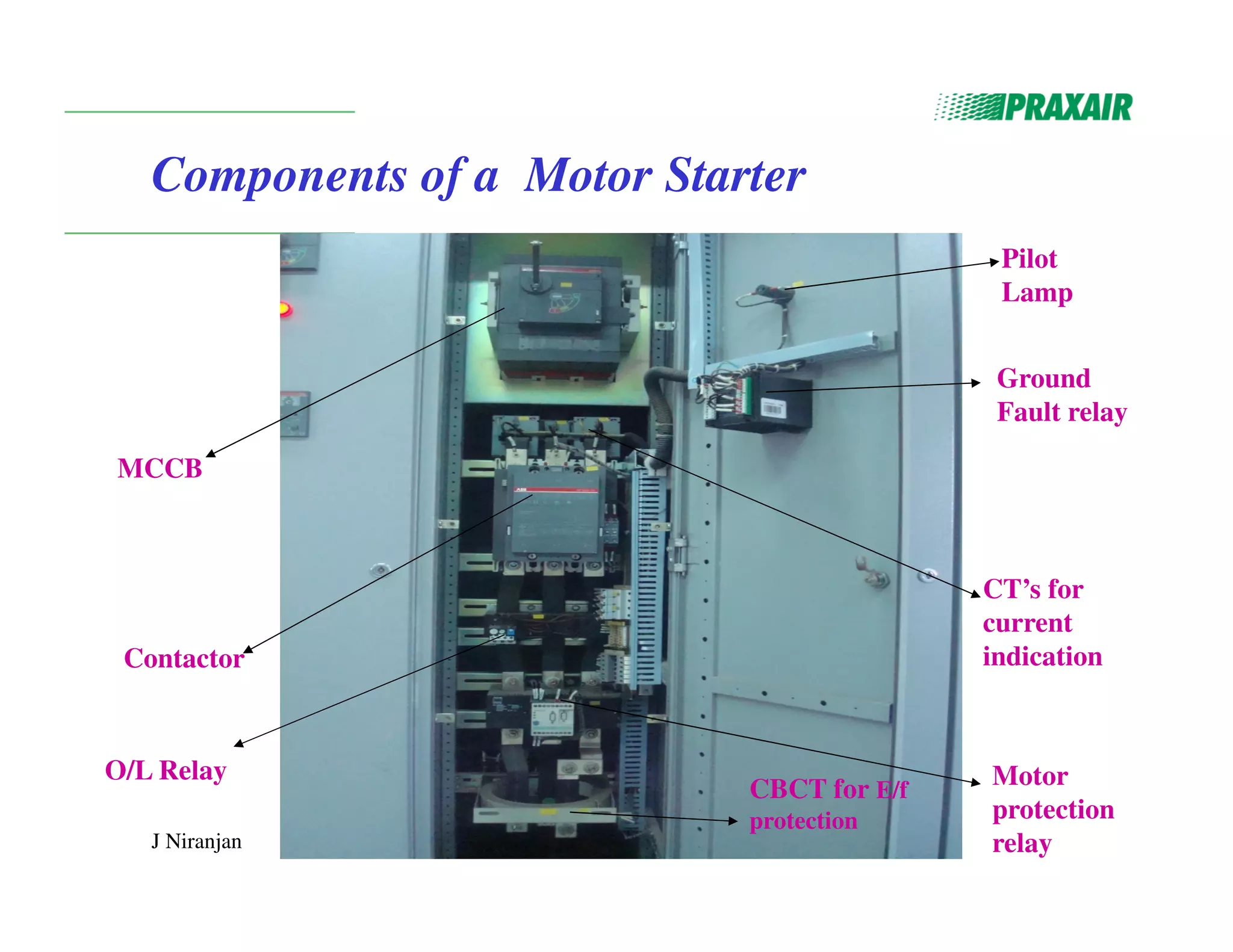
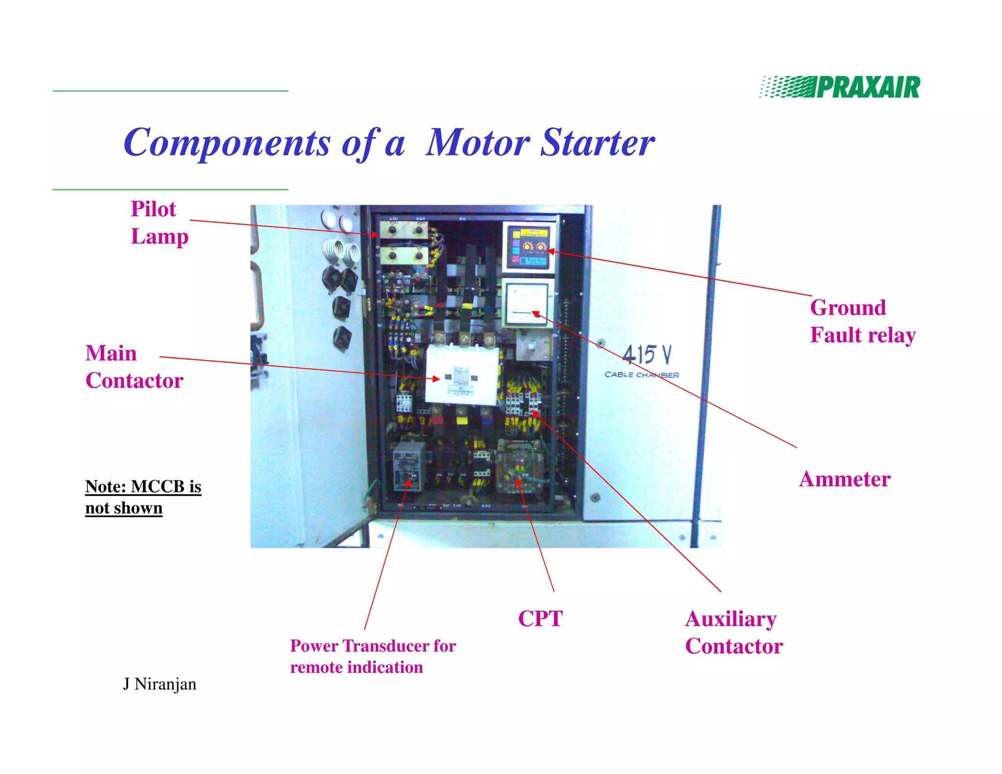
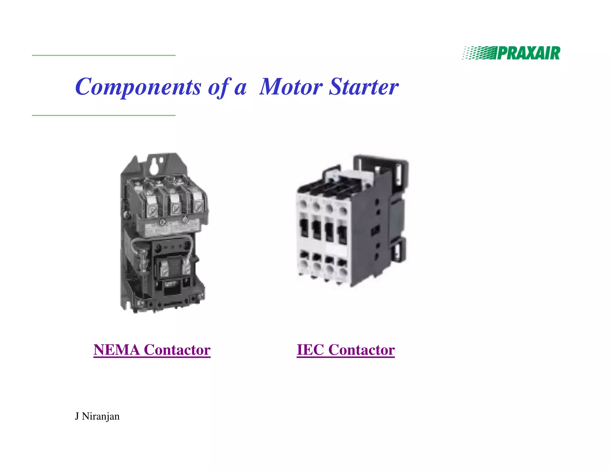
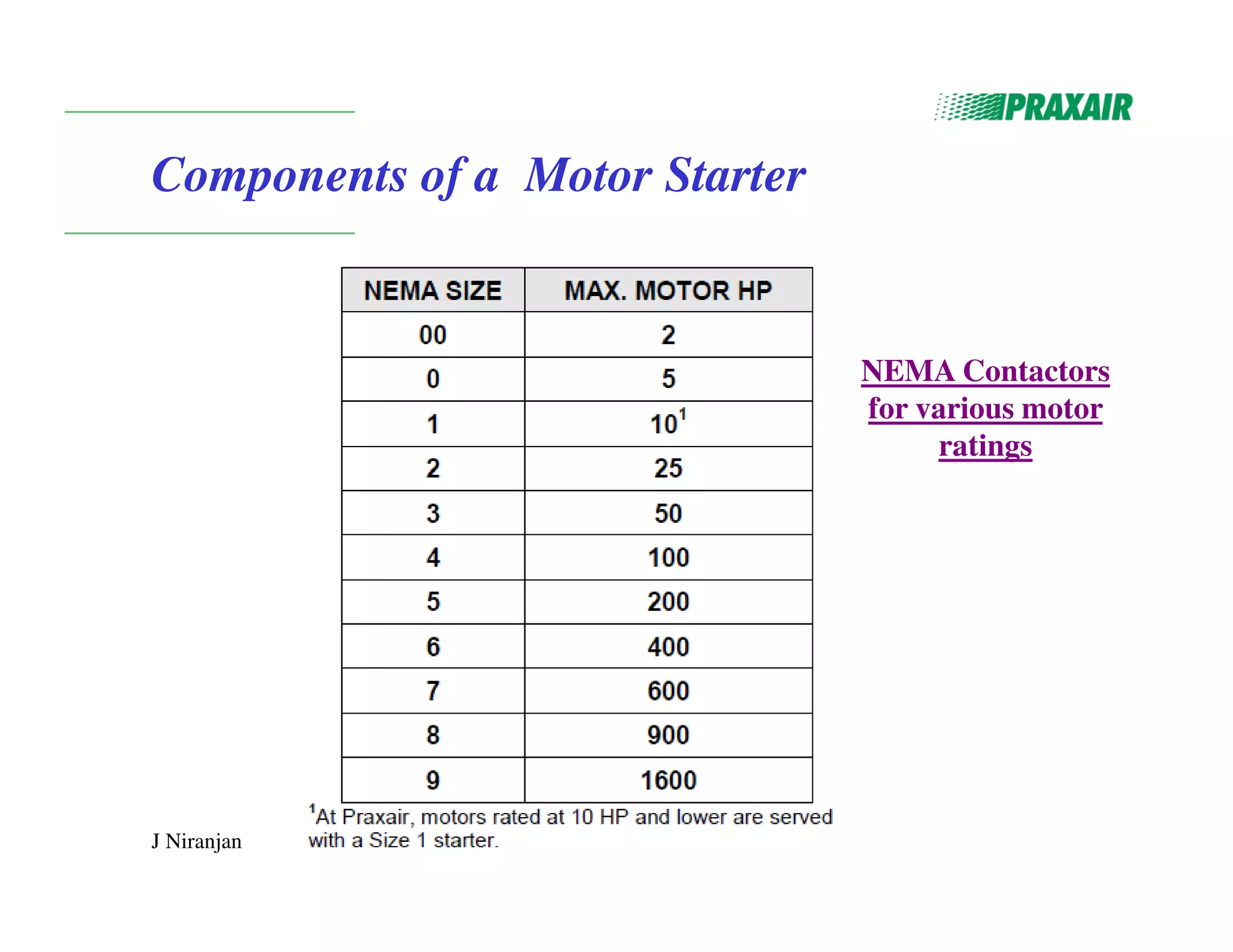
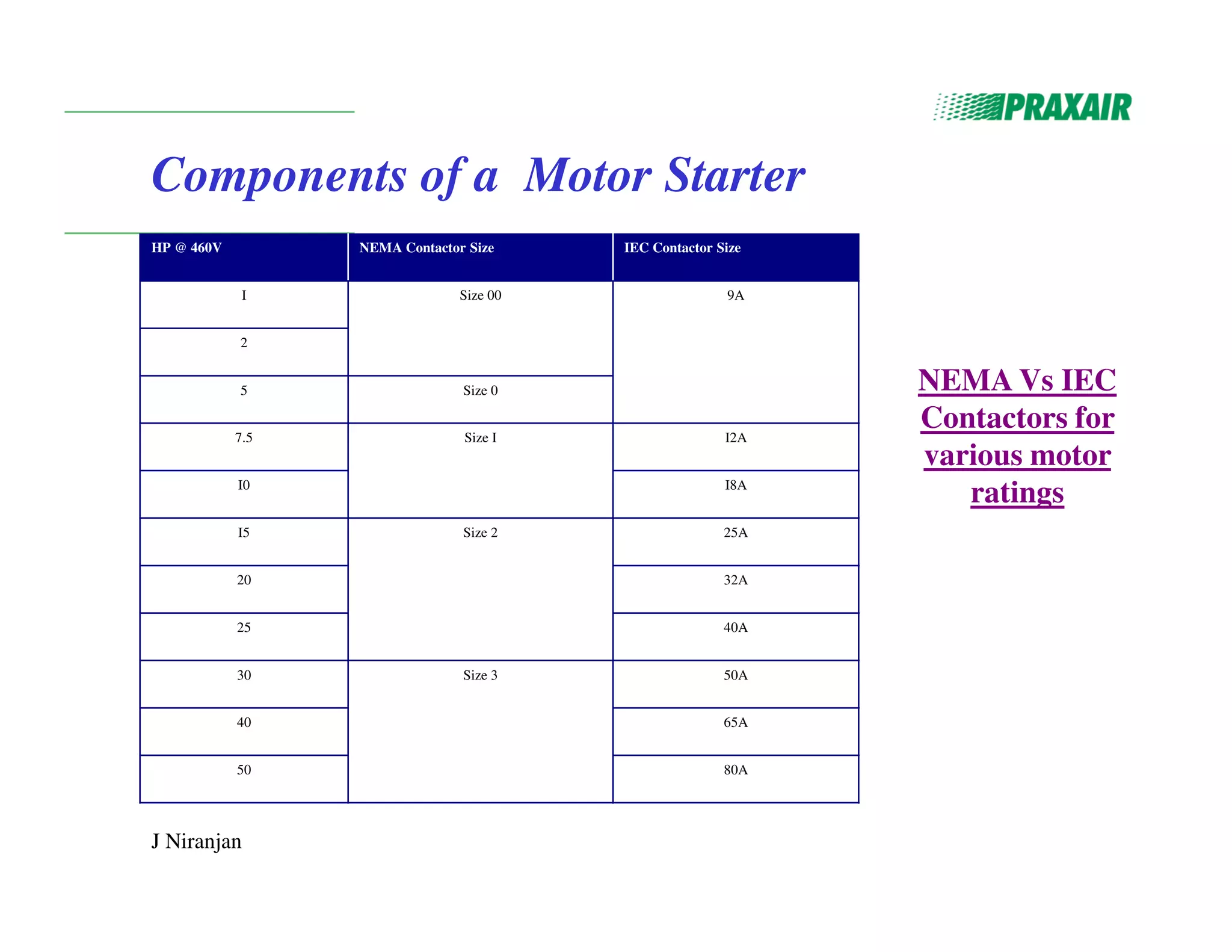
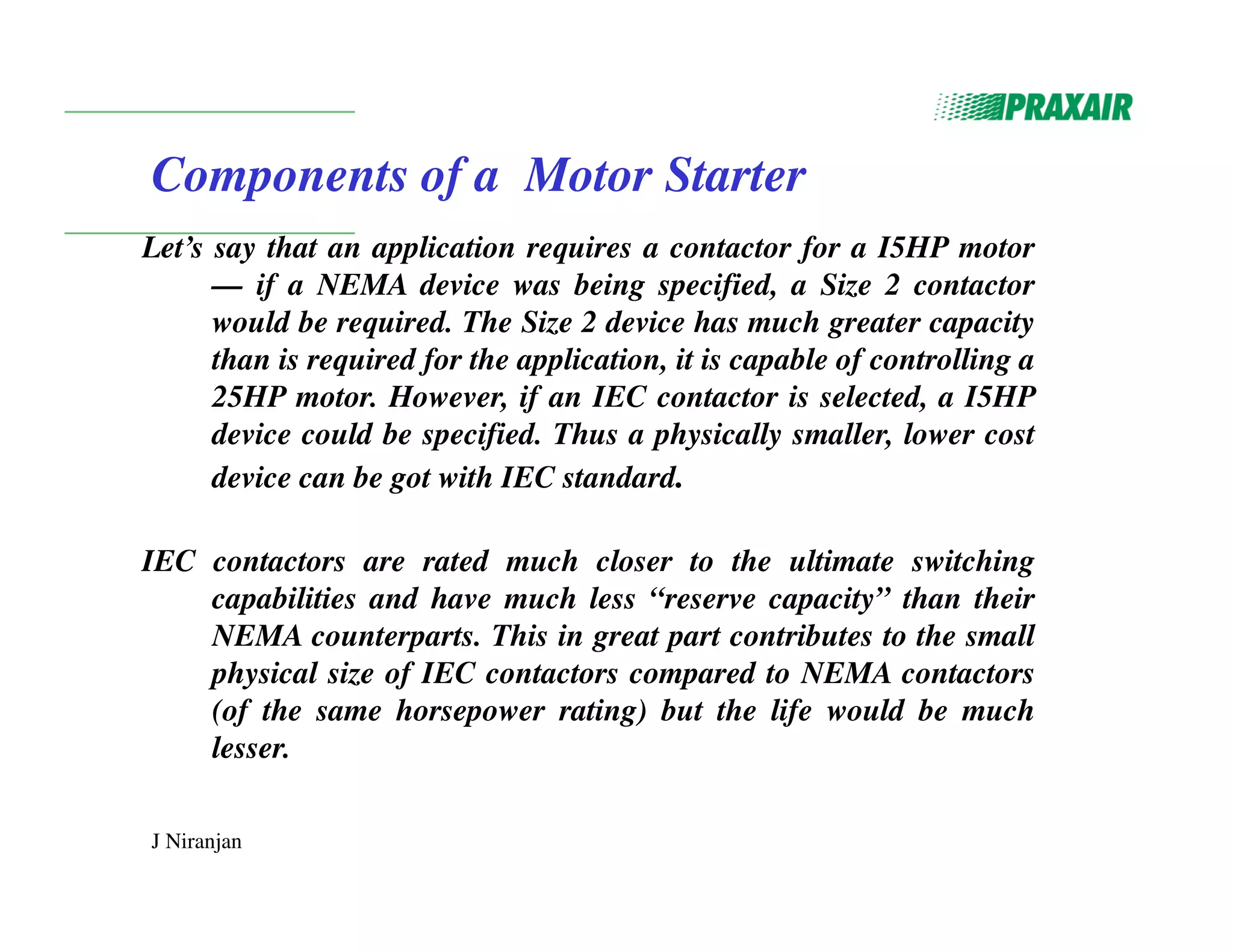
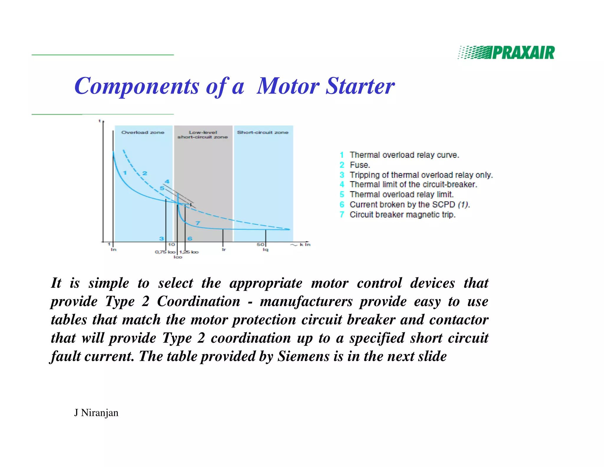
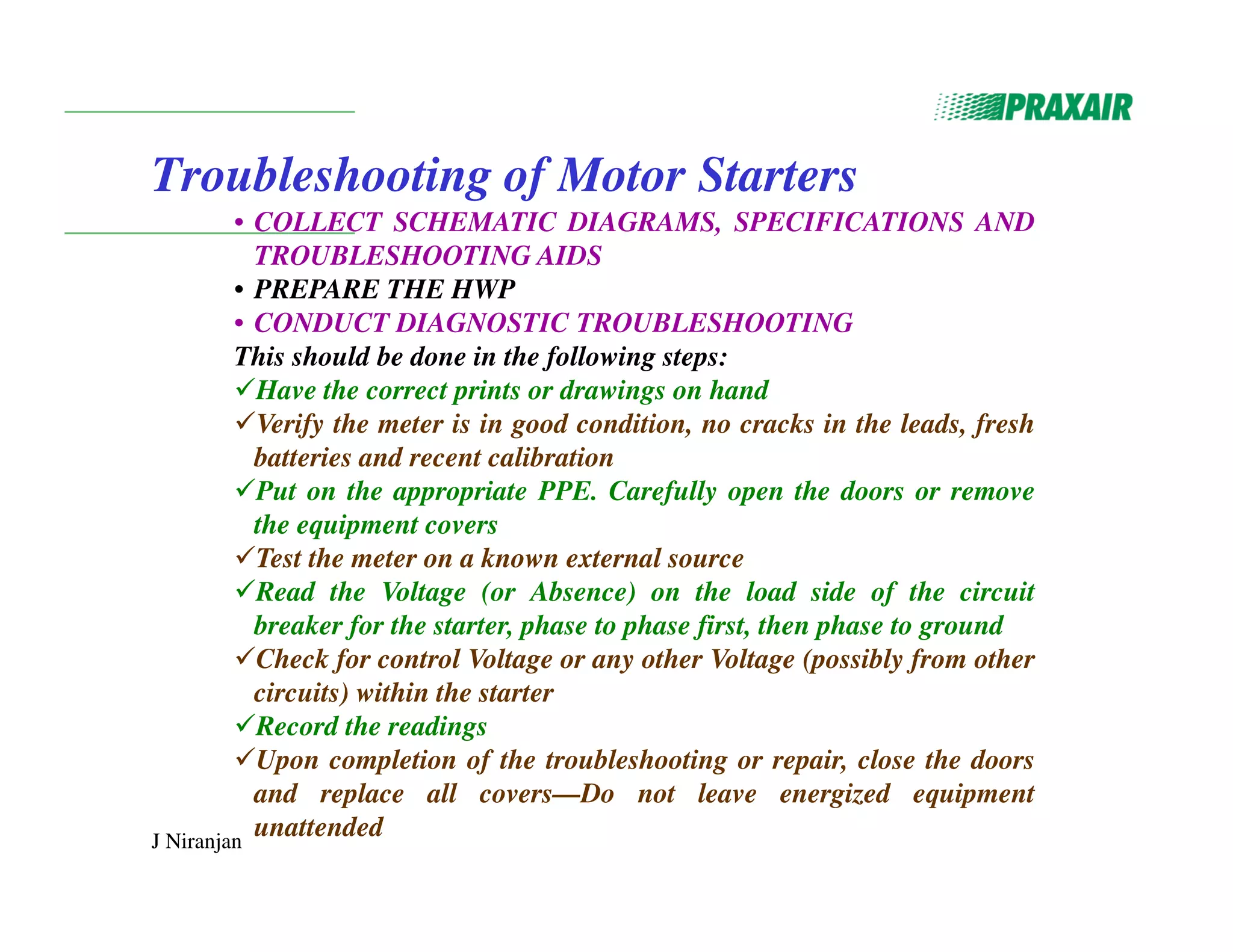
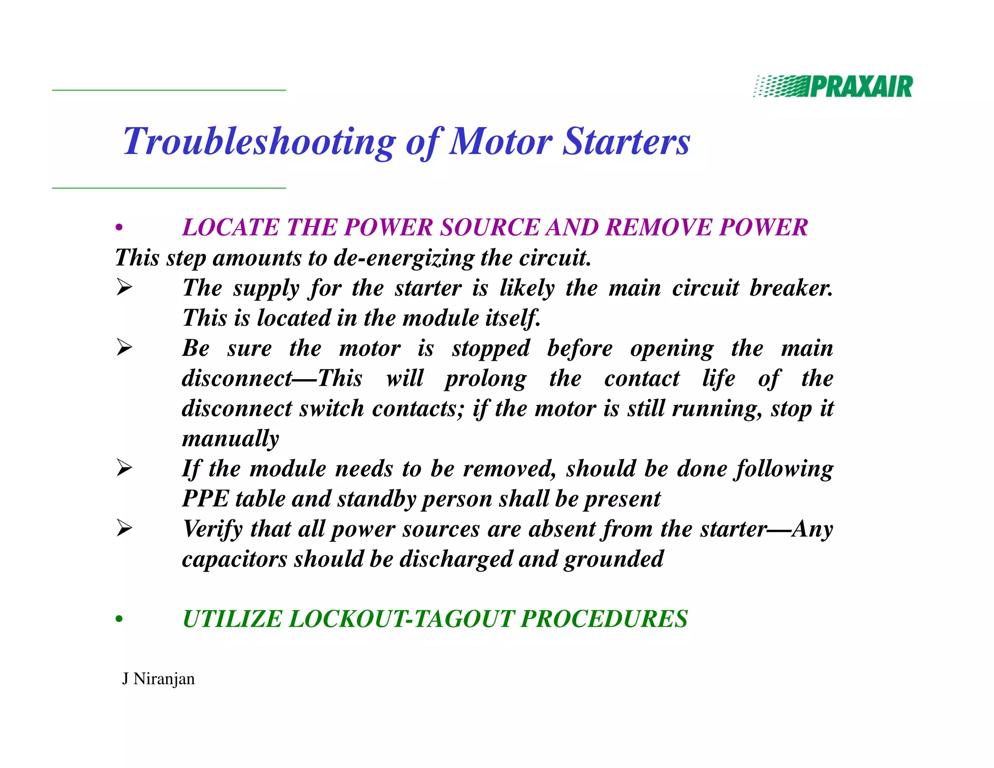
This document discusses motor starters, their components, and troubleshooting procedures. It describes the functions of motor starters as starting and stopping motors, providing remote control, and protecting motors. It explains the types of starters and components such as contactors, overload relays, and circuit breakers. It provides details on NEMA and IEC standards for these components. Finally, it outlines the steps for troubleshooting motor starters, including using lockout/tagout procedures, test equipment, and repair and restoration.
Short Circuit, Protective Device Coordinationmichaeljmack
This document discusses short-circuit calculations, protective device coordination, and arc flash analysis. It covers topics such as short-circuit fault types and calculations, the purpose of short-circuit studies, system components involved, and protective device coordination principles. Methods to perform arc flash analysis and mitigate incident energy exposure are also presented, such as improving protective device coordination settings, installing current limiting fuses or circuit breakers, and using Type 50 protective devices.
This document discusses different types of directional over current relays. It explains that directional over current relays operate when fault current flows in a particular direction and will not operate if power flows in the opposite direction. It provides details on 30 and 90 degree connections for directional relays and describes the construction and operation of non-directional over current relays and shaded pole type directional over current relays.
Este documento proporciona ejemplos de cálculos de ajustes de protección contra sobrecorriente para varios motores en un sistema eléctrico. Se calculan los ajustes para relés térmicos y interruptores asociados a motores de 50 HP, 75 HP y 200 HP, incluyendo la corriente de ajuste, la clase y la curva de tiempo. El objetivo es proteger los motores contra daños por sobrecorriente ajustando correctamente los dispositivos de protección.
The document discusses one-line diagrams, which are simplified diagrams used in power systems to represent the essential components in a simplified graphical format. A one-line diagram shows the main components of a power system like generators, transmission lines, transformers, and loads using standardized symbols. It represents the paths of power flow through the system from generation to transmission to distribution. The diagram is structured to match the physical layout. Impedance and reactance diagrams are similar but represent electrical elements like generators and lines as impedance/reactance values instead of physical components. An example calculation of voltage drop in a transmission line is provided.
The document discusses motor protection and motor control centers. It provides details on sizing conductors that supply single and multiple motors, sizing overload protection devices based on motor nameplate ratings, and protecting motors from short circuits and ground faults. It also describes the components, construction, and wiring classifications of motor control centers, which are used to control and provide protection for motors and connecting cables.
This document discusses voltage and reactive power control methods in power systems. It covers the need for reactive power to maintain voltage levels and deliver active power through transmission lines. Various reactive power compensation devices are described such as series and shunt capacitors/reactors, synchronous condensers, static VAR compensators, and static synchronous compensators. Common voltage and reactive power control methods include excitation control at generating stations, using tap changing transformers, and switching shunt reactors/capacitors depending on load levels.
This document discusses relays, including their basic components, design, operation, applications, advantages, and disadvantages. Relays are electrical devices that use electromagnets to open or close circuits. They have a coil, armature, contacts, and frame. When voltage is applied to the coil, it creates a magnetic field that moves the armature to open or close the contacts. Relays allow low power circuits to control high power circuits and are used for protection, regulation, and auxiliary functions in power systems.
This document provides guidance on estimating electric load and demand for commercial and industrial customers. It discusses:
1) How customers provide connected load based on code while utilities determine diversified demand load. Demand is typically 25-75% of connected load.
2) Methods for estimating demand loads for different equipment types like motors, air conditioning, and lighting using demand and diversity factors.
3) Typical demand factors for common equipment to check estimated demand against.
4) Using watts per square foot as a last resort when accurate load data is unavailable, such as for speculative commercial spaces.
This document provides information on a Power System Protection course taught at Vivekanandha College of Engineering for Women. The syllabus covers 5 units: introduction to protection schemes, relay operating principles and characteristics, apparatus protection, theory of circuit interruption, and circuit breakers. It lists textbooks and presents details on each unit, including topics like relay types, transformer/generator/motor protection, arc phenomena, and different circuit breaker types. The last section provides references for textbooks, websites, and presentations on related topics.
This document provides information about safety instructions and programming for an ACS 600 frequency converter, including:
- Safety warnings for working with high voltages when installing or servicing the converter. Proper precautions such as allowing capacitors to discharge must be followed.
- An overview of how the converter is programmed using parameters, macros, and a control panel. The control panel allows viewing signals, modifying parameters, and running macros.
- Descriptions of the standard application macros that are included for common control configurations like factory automation or hand/auto control. Wiring diagrams and the function of inputs/outputs are explained for each macro.
The cosine of angle made between the voltage and current is called the power factor.
In AC circuits, there is always the phase deference between the voltage and current, which is calculated in terms of power factor.
If the load is inductive the current lags behind the voltage and the power factor is lagging.
If the load is capacitive the current leads the voltage and the power factor is leading.
The value of power factor can never be more than unity.
a project report on MPPT algorithm for PV panelgauravchitransh
The document discusses renewable energy sources such as solar power. It notes that solar power has the potential to supplement power in cities and rural areas by harnessing the sun's energy through solar collectors. The document then discusses different renewable energy sources in detail, including wind power, hydropower, biomass, geothermal, and solar power. It also reviews literature on increasing the efficiency of solar panels through maximum power point tracking algorithms and circuit modeling of photovoltaic modules.
The document describes the 132kV Vaishali substation of the Uttar Pradesh Power Transmission Corporation Limited. It discusses the key components of the substation including transformers, circuit breakers, isolators, capacitor banks, relays, and more. The substation receives power from two incoming 132kV lines and distributes it to various outgoing 33kV feeders serving the local area. Diagrams are provided to illustrate the layout and components that make up the substation.
Generation of High D.C. Voltage (HVDC generation)RP6997
Generation of high dc voltage using different methods like half wave and full wave rectifier, voltage doubler circuits, voltage multiplier circuits, cockcroft-walton circuits and van de graaff generators.
The document discusses protective device coordination, including concepts, applications, features and capabilities of ETAP Star software. It covers protective device types, time current characteristic curves, short circuit analysis, device operation sequences, libraries and more. The goal is to systematically study current devices to isolate faults while limiting outages through selective coordination of protection elements.
Unit 04 Protection of generators and transformers PremanandDesai
The document discusses faults and protection methods for alternators and transformers. For alternators, common faults include failure of the prime mover, field failure, overcurrent, overspeed, overvoltage, and unbalanced or stator winding faults. Differential and inter-turn protection are described. For transformers, faults include open circuits, overheating, and winding short-circuits. Buchholz devices, earth fault relays, overcurrent relays, and differential systems provide protection. Earth fault protection for transformers uses a core-balance leakage scheme.
System protection is used to detect problems in power system components and isolate faulty equipment to maintain reliable power. The key elements of a protection system include differential relays to protect generators and transformers from internal faults, overcurrent and distance relays to protect transmission lines from external faults, and bus differential relays to protect distribution buses. Protective devices are needed to maintain acceptable operation, isolate damaged equipment, and minimize harm to personnel and property.
CONTENT
Starting Of Induction Motor
Starters
Types Of Starter For 3-ph Induction Motors
Starting Of Slip Ring Induction Motor
D.O.L.(Direct On Line) starter
Star-delta Starter
Auto Transformer Starter
Difference Between DOL/Star Delta/ Autotransformer
The document discusses unit commitment in power systems. Unit commitment involves determining which generating units to operate and when to operate them in order to meet the changing electricity demand at the lowest possible production cost while satisfying operational constraints. It describes the unit commitment problem and various constraints like minimum up/down times, ramp rates, reserve requirements, and start-up costs that make it more complex than economic dispatch. It provides a simple example to illustrate the concepts.
The document provides an overview of ETAP software for modeling AC power systems. It describes features for building a one-line diagram using auto-build and auto-connect functions. It also discusses modeling elements, running load flow analysis, creating multi-dimensional databases with study conditions and configurations, and using engineering libraries. The document uses examples to demonstrate creating a simple project, adding generators, composite networks, and circuit breakers. It also covers user access management and different types of circuit arrangements that can be modeled in ETAP.
Training report-in-a-132-k-v-substationankesh kumar
This document provides a training report for a summer internship at the Uttar Pradesh Power Corporation Limited 132/33 kV substation in Chandauli, Barabanki, India.
The report includes an introduction to the Uttar Pradesh Power Corporation and the purpose of the internship. It also provides a preface describing the learning experience and thanks to those involved.
The report then gives an acknowledgement and thanks to those who guided the internship. It provides a rough description of the Chandauli, Barabanki substation including incoming and outgoing voltages and feeders. It also includes definitions and descriptions of substations and the equipment within them.
SFRA and Tan Delta tests are used to analyze the electrical characteristics of transformers. SFRA tests measure the frequency response to detect changes from physical damage, while Tan Delta tests measure the dielectric loss to identify moisture, shorts, or opens in the windings or insulation. Together these tests help ensure the transformer is functioning properly. Ratio, voltage, magnetizing current, balance, and BDV oil tests further verify the transformer's performance and insulation strength.
This document discusses transformer overcurrent protection calculations and settings. It provides information on:
1. Coordination principles for transformer protection and examples of typical protection zones for different fault locations.
2. Guidelines for setting instantaneous and time-overcurrent relays to ensure selective coordination, including maintaining coordination intervals.
3. Calculations for determining short circuit currents and relay settings for different transformer configurations, including delta-wye transformers. Thermal and mechanical withstand curves for different transformer categories are also presented.
Electrical fault is the deviation of voltages and currents from nominal values or states. Under normal operating conditions, power system equipment or lines carry normal voltages and currents which results in a safer operation of the system.
Busbar protection uses differential protection to isolate faults on the busbar. It works by comparing the current entering and leaving the busbar using CTs - any difference indicates an internal fault. Proper CT ratios and a stabilizing resistance are needed to restrain operation for external faults. PS class CTs are preferred over other classes due to more consistent accuracy. While busbar protection is important, it is currently not implemented in line at MRSS due to some unspecified reason.
Review on Automatic Power Factor Improvement of Induction MotorIRJET Journal
This document provides a review of techniques for automatic power factor improvement of induction motors. It begins with an abstract discussing the purpose of designing new techniques for power factor improvement in 3-phase and single-phase induction motors. The document then reviews the various components involved in an automatic power factor improvement system using a microcontroller, including the power supply, zero crossing detectors, microcontroller, electromagnetic relays, LCD display, capacitor bank, and software details. It concludes that power factor correction techniques can make power systems more stable and efficient while reducing costs when using a microcontroller.
IRJET- A Mitigation of Voltage Fluctuation on Small Scale IndustryIRJET Journal
This document discusses voltage fluctuations that can damage equipment in small industries and presents a solution using a voltage stabilizer. It begins with an introduction to power quality issues like voltage sags, swells, and interruptions that are caused by problems in the power system. It then describes the components and working of a small model of a voltage stabilizer that uses a phase controller technique to regulate the voltage and maintain a constant level as the load changes, in order to protect equipment from damage caused by fluctuations. Diagrams of the circuit are provided and calculations for determining the firing angle of thyristors in the stabilizer are shown.
IRJET- Mollification Parameter Control by Dynamic Voltage Restorer (DVR)IRJET Journal
The document discusses using a Dynamic Voltage Restorer (DVR) to mitigate voltage sags. A DVR is a series-connected device that uses power electronics to quickly restore load voltage to pre-fault levels during voltage sags. It works by injecting the missing voltage back into the system. A DVR consists of an inverter, filter, booster transformer, DC storage such as capacitors, and control system. It monitors the voltage and injects only the amount needed to compensate for the sag using pulse width modulation of the inverter. This allows it to restore the voltage quickly and improve power quality for sensitive loads affected by voltage sags.
This document provides an overview of measurement and relay indications. It begins with an introduction and then discusses the functions of protection schemes, which are to sense faults, operate circuit breakers to isolate faulty equipment, and clear faults before systems become unstable. It also classifies protective relays based on technology into electromechanical, solid state, and digital/numerical relays. It describes examples and characteristics of each type. The document further discusses ANSI standard device numbers, and then describes various measuring instruments like ammeters, voltmeters, wattmeters, power factor meters, and frequency meters. It provides details on their construction, working principles, and types.
Differential Current Protection of Transformer using ArduinoIRJET Journal
1. The document describes a method for using an Arduino microcontroller for differential current protection of transformers.
2. A circuit is designed using current transformers to sense currents on the primary and secondary sides of a transformer and send the signals to an Arduino.
3. The Arduino compares the current signals and triggers an alarm and trips the circuit breaker if it detects a difference, indicating an internal fault in the transformer. This provides a more efficient protection method than using electromechanical relays.
Motor circuit breakers mmp t series dienhathe.orgDien Ha The
Khoa Học - Kỹ Thuật & Giải Trí: http://phongvan.org
Tài Liệu Khoa Học Kỹ Thuật: http://tailieukythuat.info
Thiết bị Điện Công Nghiệp - Điện Hạ Thế: http://dienhathe.vn
1. The document describes a three phase protection circuit that monitors the availability of three phase power supply and switches off connected appliances in the event of failure of one or two phases. It uses three 12V relays, a 555 timer IC, and a 230V coil contactor with four poles.
2. Key components of the protection circuit are described, including relays, contactors, 555 timer IC, diodes, zener diodes, transistors, capacitors, resistors, transformers, and optocoupler ICs. The operation of the three phase protection circuit is also explained.
3. The circuit automatically disconnects power to protected appliances through the contactor when any phase fails, and automatically restores
Protection of induction motor using classical methodIRJET Journal
This document describes a classical method for protecting induction motors from various faults. The method uses components like potential transformers, current transformers, voltage and current sensing units, a microcontroller, relays, and contactors to monitor voltage, current and detect faults like overvoltage, undervoltage, single phasing, overload, and phase reversal. When a fault is detected, the microcontroller sends a signal to trip the relays and disconnect the motor from the power supply. The system is able to protect the motor and increase its lifetime by shutting it down during faults.
IRJET- Technique to Prevent Power Theft Losses using Static DeviceIRJET Journal
This document describes a technique to prevent power theft using a static device. It aims to control voltage across a load by monitoring incoming voltage and calculating firing angles for a TRIAC. The system includes a microcontroller, zero crossing detector, TRIAC, driver circuit, and potential transformer. It can provide a constant output voltage between 210-240V even if the input voltage varies from 230-300V. For illegal consumers using banned hooks or bypassing the meter, it will provide an output of 300V to potentially damage their devices and prevent theft. The system aims to reduce theft losses for power companies and stabilize supply voltages.
This ppt is based on the working and the making of the control panelsH2SO43
The document discusses Automation & Engineering, a manufacturer of electrical panels. It describes the company's products like power control center panels, motor control center panels, and automatic power factor correction panels. It also outlines the tools, machines, components and processes used to manufacture panels, including testing procedures. The intern gained practical skills in panel manufacturing, operation, maintenance and installation during their time at the company.
Implementation of a Microcontroller Base Single Phase Automatic Changeover IJSRED
This document describes the design and implementation of a microcontroller-based single-phase automatic changeover system. The system automatically switches power sources between the main power supply and a generator in order to provide continuous power to loads. It uses a microcontroller to control relays that switch the load between available power sources. The system is designed to detect failures in the main power supply and automatically start the generator to power the load until main power is restored, at which point it switches back. The system aims to provide uninterrupted power for applications requiring continuous power such as hospitals, banks, and other critical systems.
IRJET- Power Quality Improvement using Dynamic Voltage Restorer (DVR)IRJET Journal
1) The document discusses power quality issues such as voltage sags and proposes using a Dynamic Voltage Restorer (DVR) to improve power quality.
2) A DVR injects voltage into the distribution system through an injection transformer to compensate for voltage sags and restore the load voltage to its normal level.
3) The document presents a MATLAB simulation of a DVR connected to a distribution system with two loads - a sensitive load and a normal load. When a fault is created, the DVR injects voltage and is able to maintain the sensitive load voltage at its normal level, protecting it from the voltage sag.
Mitigation of voltage sag/swell using Dynamic voltage restorer (DVR)IOSR Journals
This document discusses the use of a Dynamic Voltage Restorer (DVR) to mitigate voltage sags and swells on electrical distribution systems. It begins with an introduction to power quality issues like voltage sags and the need to protect sensitive industrial and commercial loads. The DVR is described as a series-connected power electronics device that can quickly inject voltage to restore the load voltage during a sag or swell event. The document then covers the basic components, control strategies, and modeling of DVR systems to mitigate voltage disturbances. It analyzes the technical benefits and applications of DVRs compared to other power quality solutions and explores their optimal placement in distribution systems.
This document provides information about various electrical components including MCCB, air circuit breaker, control gear, capacitor, load bank, and testing procedures. It discusses MCCBs, including types (G-frame, A-frame, etc.), testing procedures for thermal, magnetic, trip/not trip, and mechanical endurance testing. Information is also given on air circuit breakers, contactors, thermal overload relays, capacitors, load banks, APFC panels, busbar chambers, and MCCB enclosures.
This document provides an overview of a seminar on power factor improvement using microcontrollers. It discusses key topics like what power factor is, causes of low power factor, automatic power factor correction using hardware components like a microcontroller, voltage regulator, power supply, relay, LCD display, and capacitor bank. The document outlines the advantages of power factor correction like reduced transformer rating, line losses, and equipment size. It concludes that using microcontrollers for automatic power factor correction makes power systems more stable and efficient while reducing costs compared to manual correction.
Minimizing Penalty in Industrial Power Consumption by Engaging APFC Unit : A ...IRJET Journal
This document summarizes a research paper on minimizing penalties in industrial power consumption by using automatic power factor correction (APFC) units. It discusses how inductive loads in industries reduce the power factor below standards set by electricity boards, resulting in penalties. An APFC device uses a microcontroller to measure voltage, current, power factor and automatically switch capacitor banks to compensate for reactive power and improve the power factor. Test results showed the power factor increased from 0.67 to 0.95 after installing the APFC unit, reducing penalties for the industrial consumer. The automatic switching of capacitors provides a more accurate method of power factor correction compared to manual switching.
LOW VOLTAGE CONTROL PANEL, SWITHGEAR, OVERLOAD PROTECTION, STARTING METHODSJayant Suthar
The document summarizes training provided by Birla Professional Training & Research Centre (BPTRC) on electrical motors, control panels, and PLC automation. The training covered types of electric motors, terminal markings, connection arrangements, and protection devices. It also covered low voltage control panels, switchgear components, contactors, overload protection methods, and motor starting methods. Students learned about electrical components, PLC programming, and applications in industrial control through hands-on labs. The conclusion states the training helped students understand technical specifications, protection concepts, starting methods, and knowledge required for work in industry.
Similar to motor starters and their troubleshooting.pdf (20)
This document discusses types and patterns of partial discharge in electrical equipment. It identifies common defect locations that cause partial discharge, including internal voids, delamination between insulation layers, and defects in end windings or slots. For each defect type, the document provides characteristic values like polarity predominance, probable phase angles of occurrence, and how temperature, humidity, and load affect the partial discharge pattern. Visual examples are also provided to help with identification of partial discharge in equipment. The next meeting agenda is listed as focusing on case studies of partial discharge.
This document summarizes a case study of a partial discharge failure in the motor of an air separation unit at a gas production plant in China. The key points are:
1) In January 2022, the motor's A-phase winding failed due to internal voids causing a ground fault that tripped protection in 35 milliseconds. Trend analysis did not detect any alarms prior to failure.
2) Analysis of long-term trend data going back 3-4 years showed a gradual rise in partial discharge intensity and pulse counts that could have predicted the failure if monitored more closely.
3) Examination of phase resolved data from the past year showed signs of slot discharge in the failed phase that were initially below alarm
This document provides instructions for commissioning checks when installing a Partial Discharge Monitoring system. It outlines steps to ensure proper signal transmission from sensors to the monitoring device, including installing sensors close to motor windings, avoiding signal suppression from surge caps, checking coaxial cabling is properly installed, and performing sensitivity checks by injecting defined partial discharge signals and measuring the system's response. Locations for installing RTD sensors for partial discharge detection and ensuring their proper grounding is also covered. The document aims to ensure high quality commissioning to accurately detect partial discharge signals.
The document provides an overview of partial discharge detection as part of condition-based maintenance of electrical equipment. It discusses concepts like partial discharge mechanisms, the components used for partial discharge detection, and how online partial discharge detection can help monitor insulation health and provide early warnings of degradation. The document also covers topics like common types of partial discharges, how insulation defects can lead to partial discharges, and how partial discharges gradually deteriorate insulation over time if not addressed.
This document provides an overview of an electrical wiring textbook. It includes a table of contents listing 6 chapters that cover topics like construction plans, sitework, unit substations, feeder bus systems, panelboards, trolley busways, and determining conductor sizes. The document notes that some third party content may be suppressed due to electronic rights restrictions. It provides publishing information for the textbook, including copyright and ISBN numbers.
This document provides an overview of insulation resistance measurement and testing. It discusses the importance of insulation integrity testing, how insulation resistance is measured using an insulation resistance tester, proper testing techniques and safety considerations, and how to interpret insulation resistance readings and polarization index values. The key points covered are how to select the appropriate tester voltage, connect the tester for measurements, ensure safety, and evaluate insulation condition based on resistance values and polarization index.
The document provides information on troubleshooting and replacing LT motors. It describes common motor malfunctions such as not running, failing to start, overheating, excessive vibration, running slow, and tripping ground fault relays. For each issue, it lists probable causes and troubleshooting procedures to identify the root cause. The procedures include checking for blown fuses, low voltage, mechanical overloads, shorted coils, and other potential problems. Guidelines are provided for safely locking out power, removing the old motor, installing the new one, and restoring power connections.
Batteries -Introduction – Types of Batteries – discharging and charging of battery - characteristics of battery –battery rating- various tests on battery- – Primary battery: silver button cell- Secondary battery :Ni-Cd battery-modern battery: lithium ion battery-maintenance of batteries-choices of batteries for electric vehicle applications.
Fuel Cells: Introduction- importance and classification of fuel cells - description, principle, components, applications of fuel cells: H2-O2 fuel cell, alkaline fuel cell, molten carbonate fuel cell and direct methanol fuel cells.
Using recycled concrete aggregates (RCA) for pavements is crucial to achieving sustainability. Implementing RCA for new pavement can minimize carbon footprint, conserve natural resources, reduce harmful emissions, and lower life cycle costs. Compared to natural aggregate (NA), RCA pavement has fewer comprehensive studies and sustainability assessments.
Understanding Inductive Bias in Machine LearningSUTEJAS
This presentation explores the concept of inductive bias in machine learning. It explains how algorithms come with built-in assumptions and preferences that guide the learning process. You'll learn about the different types of inductive bias and how they can impact the performance and generalizability of machine learning models.
The presentation also covers the positive and negative aspects of inductive bias, along with strategies for mitigating potential drawbacks. We'll explore examples of how bias manifests in algorithms like neural networks and decision trees.
By understanding inductive bias, you can gain valuable insights into how machine learning models work and make informed decisions when building and deploying them.
Presentation of IEEE Slovenia CIS (Computational Intelligence Society) Chapte...University of Maribor
Slides from talk presenting:
Aleš Zamuda: Presentation of IEEE Slovenia CIS (Computational Intelligence Society) Chapter and Networking.
Presentation at IcETRAN 2024 session:
"Inter-Society Networking Panel GRSS/MTT-S/CIS
Panel Session: Promoting Connection and Cooperation"
IEEE Slovenia GRSS
IEEE Serbia and Montenegro MTT-S
IEEE Slovenia CIS
11TH INTERNATIONAL CONFERENCE ON ELECTRICAL, ELECTRONIC AND COMPUTING ENGINEERING
3-6 June 2024, Niš, Serbia
Embedded machine learning-based road conditions and driving behavior monitoringIJECEIAES
Car accident rates have increased in recent years, resulting in losses in human lives, properties, and other financial costs. An embedded machine learning-based system is developed to address this critical issue. The system can monitor road conditions, detect driving patterns, and identify aggressive driving behaviors. The system is based on neural networks trained on a comprehensive dataset of driving events, driving styles, and road conditions. The system effectively detects potential risks and helps mitigate the frequency and impact of accidents. The primary goal is to ensure the safety of drivers and vehicles. Collecting data involved gathering information on three key road events: normal street and normal drive, speed bumps, circular yellow speed bumps, and three aggressive driving actions: sudden start, sudden stop, and sudden entry. The gathered data is processed and analyzed using a machine learning system designed for limited power and memory devices. The developed system resulted in 91.9% accuracy, 93.6% precision, and 92% recall. The achieved inference time on an Arduino Nano 33 BLE Sense with a 32-bit CPU running at 64 MHz is 34 ms and requires 2.6 kB peak RAM and 139.9 kB program flash memory, making it suitable for resource-constrained embedded systems.
Electric vehicle and photovoltaic advanced roles in enhancing the financial p...IJECEIAES
Climate change's impact on the planet forced the United Nations and governments to promote green energies and electric transportation. The deployments of photovoltaic (PV) and electric vehicle (EV) systems gained stronger momentum due to their numerous advantages over fossil fuel types. The advantages go beyond sustainability to reach financial support and stability. The work in this paper introduces the hybrid system between PV and EV to support industrial and commercial plants. This paper covers the theoretical framework of the proposed hybrid system including the required equation to complete the cost analysis when PV and EV are present. In addition, the proposed design diagram which sets the priorities and requirements of the system is presented. The proposed approach allows setup to advance their power stability, especially during power outages. The presented information supports researchers and plant owners to complete the necessary analysis while promoting the deployment of clean energy. The result of a case study that represents a dairy milk farmer supports the theoretical works and highlights its advanced benefits to existing plants. The short return on investment of the proposed approach supports the paper's novelty approach for the sustainable electrical system. In addition, the proposed system allows for an isolated power setup without the need for a transmission line which enhances the safety of the electrical network
DEEP LEARNING FOR SMART GRID INTRUSION DETECTION: A HYBRID CNN-LSTM-BASED MODELgerogepatton
As digital technology becomes more deeply embedded in power systems, protecting the communication
networks of Smart Grids (SG) has emerged as a critical concern. Distributed Network Protocol 3 (DNP3)
represents a multi-tiered application layer protocol extensively utilized in Supervisory Control and Data
Acquisition (SCADA)-based smart grids to facilitate real-time data gathering and control functionalities.
Robust Intrusion Detection Systems (IDS) are necessary for early threat detection and mitigation because
of the interconnection of these networks, which makes them vulnerable to a variety of cyberattacks. To
solve this issue, this paper develops a hybrid Deep Learning (DL) model specifically designed for intrusion
detection in smart grids. The proposed approach is a combination of the Convolutional Neural Network
(CNN) and the Long-Short-Term Memory algorithms (LSTM). We employed a recent intrusion detection
dataset (DNP3), which focuses on unauthorized commands and Denial of Service (DoS) cyberattacks, to
train and test our model. The results of our experiments show that our CNN-LSTM method is much better
at finding smart grid intrusions than other deep learning algorithms used for classification. In addition,
our proposed approach improves accuracy, precision, recall, and F1 score, achieving a high detection
accuracy rate of 99.50%.
2. J Niranjan
Introduction to Motor Starters
Functions of a Motor Starter
Starting and stopping the motor (or other device)
Provide remote control to the motor or heater
Limit the current inrush
Reverse the motor
Control the speed of the motor
Protect the motor from overloading/over-speeding
overheating or ground fault conditions
3. J Niranjan
Introduction to Motor Starters
Types of Starters
Direct On Line Starters (DOL) or Across the line
Starters
Reduced Voltage Starters – Achieved by means of
1) Solid State Devices (Soft-starters, VFD’s)
2) Auto Transformers
3) Reactors
4) Star/Delta connections
4. J Niranjan
Components of a Motor Starter
MCCB
Contactor
O/L Relay
Ground
Fault relay
CT’s for
current
indication
Motor
protection
relay
Pilot
Lamp
CBCT for E/f
protection
5. J Niranjan
Components of a Motor Starter
Main
Contactor
CPT
Ground
Fault relay
Ammeter
Pilot
Lamp
Auxiliary
Contactor
Power Transducer for
remote indication
Note: MCCB is
not shown
6. J Niranjan
Components of a Motor Starter
Contactors
Definition: An electromechanical device that opens and
closes a power circuit. Generally operated
magnetically, providing remote control, but can also
be operated manually. Power is controlled when the
contactor’s contacts open and close.
Function: To control motors (most common) and other
power circuits (e.g. transformers, heaters, lights, and
capacitors).
7. J Niranjan
Components of a Motor Starter
Contactors
There are two main types of contactors used in industrial applications
— contactors designed to NEMA standards and contactors
designed to IEC standards
Traditional NEMA contactors are designed to meet the size ratings
(00, 0, 1, 2 … 9) specified in NEMA standards. A NEMA
contactor is designed by convention with sufficient reserve
capacity to assure performance over a broad range of
applications
Traditional IEC contactors are designed to match a contactor to a
load, expressed in both the contactor’s rating and expected life.
IEC standards do not define standard sizes — the manufacturer
can choose to apply any rating based on meeting the
performance and test requirements of the IEC standards.
10. J Niranjan
Components of a Motor Starter
NEMA Vs IEC
Contactors for
various motor
ratings
HP @ 460V NEMA Contactor Size IEC Contactor Size
I Size 00 9A
2
5 Size 0
7.5 Size I I2A
I0 I8A
I5 Size 2 25A
20 32A
25 40A
30 Size 3 50A
40 65A
50 80A
11. J Niranjan
Components of a Motor Starter
Let’s say that an application requires a contactor for a I5HP motor
— if a NEMA device was being specified, a Size 2 contactor
would be required. The Size 2 device has much greater capacity
than is required for the application, it is capable of controlling a
25HP motor. However, if an IEC contactor is selected, a I5HP
device could be specified. Thus a physically smaller, lower cost
device can be got with IEC standard.
IEC contactors are rated much closer to the ultimate switching
capabilities and have much less “reserve capacity” than their
NEMA counterparts. This in great part contributes to the small
physical size of IEC contactors compared to NEMA contactors
(of the same horsepower rating) but the life would be much
lesser.
12. J Niranjan
Components of a Motor Starter
OVERLOAD RELAYS
Definition: Electromechanical device that prevents
damage to a motor caused by excessive current.
When an overload relay senses that a motor is
overheating (eg. drawing too much current over a
specific period of time), the overload relay will trip,
removing power to the motor (by interrupting the
contact or coil circuit).
Function: To protect the windings of motors and the
conductors to the motor against overload currents.
13. J Niranjan
Components of a Motor Starter
Traditional NEMA thermal overload relays typically accept
interchangeable, field installable heater elements. Each
overload relay will accept different heater elements based on the
maximum current rating of the overload relay or the contactor
size if the overload relay is to be directly installed on the
contactor. The heater elements are typically eutectic alloy
(although bimetal constructions are also available), and are
indirectly heated. Heater elements are available with trip
Classes 10, 20, and 30.
Traditional IEC thermal overload relays include integral, directly
heated bimetal elements. Typically these overload relays have
an adjustable current setting, marked in amperes. The
minimum to maximum adjustment range is approximately 1:1.5
(ex. 10A to 15A
17. J Niranjan
Components of a Motor Starter
Motor Protection Circuit Breakers
Definition: A circuit breaker that is assembled as an integral unit in
a supporting and enclosing housing of insulating material.
Thermal elements (various trip classes available, typically class
10) are ambient temperature compensated for precise overload
protection of motor windings, and include phase loss protection.
18. J Niranjan
Components of a Motor Starter
Function: Motor Protection Circuit Breakers are multi-
function devices designed to:
Manually control motors (most common) and other
power circuits
(e.g. transformers, heaters, and lights)
Protect the windings of motors and the conductors of the
motor against overload currents
Protect motor circuit components (contactors, overload
relays, and motors) and the conductors to the motor
against short circuit currents
Disconnect all of the motor circuit conductors
simultaneously from their source of supply
19. J Niranjan
Components of a Motor Starter
Short Circuit Protective Devices
There are a number of choices of short circuit protective
devices including fuses, molded case circuit breakers,
and motor circuit protectors. Even though they are
not “motor control devices” they are closely
associated with and used with motor control devices.
All Installation Codes and Standards dictate, a short
circuit protective device is required in every motor
branch circuit
20. J Niranjan
Components of a Motor Starter
Short Circuit Protective Devices
Fuses
Definition:
An overcurrent protective device with a fusible link
that operates (one-time only) to open the circuit on
an overcurrent condition.
Function:
Protect motor circuit components (contactors,
overload relays, and motors) and the conductors to
the motor against short circuit currents
Protect the motor circuit conductors against overload
currents
21. J Niranjan
Components of a Motor Starter
Short Circuit Protective Devices
Molded Case Circuit Breakers
Definition: A device that is assembled as an integral unit in a
supporting and enclosing housing of insulating
material, designed to open and close a circuit by non-
automatic means and to open the circuit automatically
on a predetermined overcurrent (short circuit or
overload), without injury to itself when properly
applied within its rating.
Function: Protect motor circuit components (contactors, overload
relays, and motors) and the conductors to the motor
against short circuit currents
Protect the motor circuit conductors against overload
currents
Disconnect all of the motor branch circuit conductors
simultaneously from their source of supply
22. J Niranjan
Components of a Motor Starter
TYPE 2 CO-ORDINATION
Type 2 Coordination means that a starter will not be
damaged in the event of a short circuit fault.
Following is the definition from IEC 60947-4-1:
Type 2 Coordination: under short-circuit conditions, the
contactor or starter shall cause no danger to persons
or installation and shall be suitable for further use.
The risk of contact welding is recognized, in which
case the manufacturer shall indicate the measures to
be taken with regard to the maintenance of the
equipment.
23. J Niranjan
Components of a Motor Starter
TYPE 2 CO-ORDINATION
By specifying Type 2 Coordination, safety to personnel is enhanced
because arc flashes resulting from short circuit faults can be
eliminated.
In addition to enhanced safety, Type 2 Coordination provides the
following benefits:
Reduced component replacement costs
Increased productivity
Simple device selection
Component replacement costs are reduced because contactors,
starters, and motor protection circuit breakers are protected against
damage — so they don’t need to be repaired or replaced after a short
circuit fault.
24. J Niranjan
Components of a Motor Starter
It is simple to select the appropriate motor control devices that
provide Type 2 Coordination - manufacturers provide easy to use
tables that match the motor protection circuit breaker and contactor
that will provide Type 2 coordination up to a specified short circuit
fault current. The table provided by Siemens is in the next slide
26. J Niranjan
Troubleshooting of Motor Starters
• COLLECT SCHEMATIC DIAGRAMS, SPECIFICATIONS AND
TROUBLESHOOTING AIDS
• PREPARE THE HWP
• CONDUCT DIAGNOSTIC TROUBLESHOOTING
This should be done in the following steps:
Have the correct prints or drawings on hand
Verify the meter is in good condition, no cracks in the leads, fresh
batteries and recent calibration
Put on the appropriate PPE. Carefully open the doors or remove
the equipment covers
Test the meter on a known external source
Read the Voltage (or Absence) on the load side of the circuit
breaker for the starter, phase to phase first, then phase to ground
Check for control Voltage or any other Voltage (possibly from other
circuits) within the starter
Record the readings
Upon completion of the troubleshooting or repair, close the doors
and replace all covers—Do not leave energized equipment
unattended
27. J Niranjan
Troubleshooting of Motor Starters
• LOCATE THE POWER SOURCE AND REMOVE POWER
This step amounts to de-energizing the circuit.
The supply for the starter is likely the main circuit breaker.
This is located in the module itself.
Be sure the motor is stopped before opening the main
disconnect—This will prolong the contact life of the
disconnect switch contacts; if the motor is still running, stop it
manually
If the module needs to be removed, should be done following
PPE table and standby person shall be present
Verify that all power sources are absent from the starter—Any
capacitors should be discharged and grounded
• UTILIZE LOCKOUT-TAGOUT PROCEDURES
28. J Niranjan
Troubleshooting of Motor Starters
• UTILIZE TEST EQUIPMENT TO
TROUBLESHOOT AND ISOLATE CAUSE
Troubleshooting of circuits necessitates using the
proper test equipment within its ratings. Most low
Voltage test equipment suited for industrial use is
rated at 1000 volts dc. Different types of test
equipment are used for different purposes. These
test equipments include digital multi-meter, clamp
on Ammeter, DLRO, Megger etc.
29. J Niranjan
Tests on Various Components
•Main circuit breaker –
Rarely is the problem here, however contact resistance should
be tested with a DLRO, trip time can also be tested with a high
current test set.
•Control power transformer
CPT—normally energized when circuit breaker is on. Check
fuses and continuity of primary and secondary windings.
30. J Niranjan
Tests on Various Components
Contactor coil
Measure continuity with an ohmmeter (DMM). The values will vary
depending on the contactor model. Some bigger sized contactors use
a ‘DC’ coil and hence the AC control supply is rectified and fed to the
coil. In this case the continuity cannot be checked
Auxiliary switch contacts
Measure continuity with DMM. Contacts should follow armature:
The ‘NO’ contact (‘a’ contact – has a suffix number 3-4)makes with
main , the ‘NC’ contact (‘b’ contact – has a suffix number 1-2)breaks
when main makes
31. J Niranjan
Tests on Various Components
Current Transformers
Measure for continuity with ohmmeter, make sure
leads are clean and tightly connected.
32. J Niranjan
Tests on Various Components
Ground fault relay (Contd.)
Ground fault relays must be manually reset. Causes of
ground faults are moisture, insulation damage or
deterioration, or unintentional connections of neutral
and ground conductors downstream from the main
service.
In any case, the cause of the ground fault must be
determined before the circuit is re-energized.
33. J Niranjan
TEST PROCEDURES
•SET UP A TEST CIRCUIT
One of the best means of checking out the starter or any of its
individual components is to set up a test circuit. A variac can
be used to inject this control supply. In some MCC’s, there is a
‘test’ facility, which energizes only the control supply and can
be used
34. J Niranjan
TEST PROCEDURES
•OPERATE THE TEST CIRCUIT
There are some safety rules to follow when checking
components with a test circuit.
Warning: Whenever using an external Voltage to test a
component in a starter, you must ensure that the device under
test is isolated from all other, so there is no possibility of
backfeed or accidental energization
Test circuits are easily used and operated when the device is
out of the starter and placed on the bench. However, in real
world troubleshooting, it is not always practical to take a
contactor or relay out of the MCC for testing. In fact, it is
usually prohibitive.
35. J Niranjan
Tests on Various Components
Isolate the Device—
Great care must be exercised so that the component under test
cannot energize another component, specifically, if you test the
main contactor with an external 110 Volt supply, you don’t
want the motor to actually start
Watch for Interlocks-
In a reversing starter, or a two-speed starter, the two contactors
are electrically and mechanically interlocked so that only one
can be closed at once. Again, avoid energizing an interlocked
device. Even though there may be no electrical hazard (the
input power will have de-energized) but the mechanical
linkage can be damaged by the power of a large contactor.
36. J Niranjan
REPAIR AND RESTORATION
•REPAIR CIRCUIT OR REPLACE DEFECTIVE
COMPONENT
Replace the defective device with a like device that is
either new or known to be fully operational. If there is
doubt, then the replacement unit should be tested before
installation if possible. In most cases, any circuits or
devices repaired, particularly feeders should be meggered
to verify that no conductors are shorted or grounded.
•CLEAR THE AREA AND REMOVE THE
LOCKOUT
As in the normal LOTO procedure, notify all affected
personnel that the power is about to be restored. Remove
any temporary grounds, barriers and warning signs and
remove the LOCK OUT.
37. J Niranjan
REPAIR AND RESTORATION
•RESTORE POWER
Before inserting the fuses or closing the circuit breaker, be sure all
controls are in the OFF or MANUAL positions so that equipment
does not start up when the control circuit is energized. Using the
proper techniques, close the CB (or install the fuses). Immediately
verify that control power is present and within the proper Voltage
range. (control fuses may blow due to CPT inrush and hence voltage
checking is necessary)
•TEST OPERATION
Again, any affected personnel should be notified that the starter is
about to be tested and that the motor will be starting. The motor
should be brought on in the normal mode by remote controls.
38. J Niranjan
REPAIR AND RESTORATION
•RESTORE SERVICE
Provided that the operational tests are successful, then the control
selectors can be set to the RUN or AUTOMATIC mode. When the
control circuit has been restored, then is should be observed for
proper operation.
•DOCUMENT THE REPAIR, CORRECT DRAWINGS
No job is complete until the documentation is done through 7i. Any
changes made in wiring to accommodate new components should be
marked in on the schematic diagram and highlighted in a different
color ink (red).
If required, a RCA (root cause analysis) should be conducted
immediately.