
Downloaded 272 times


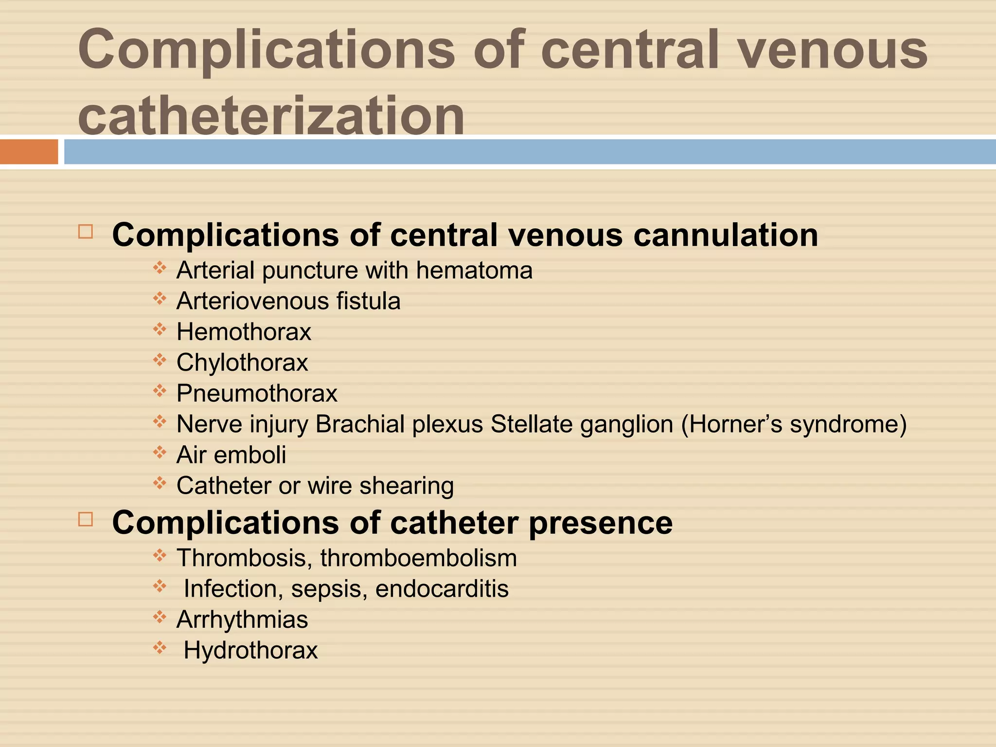


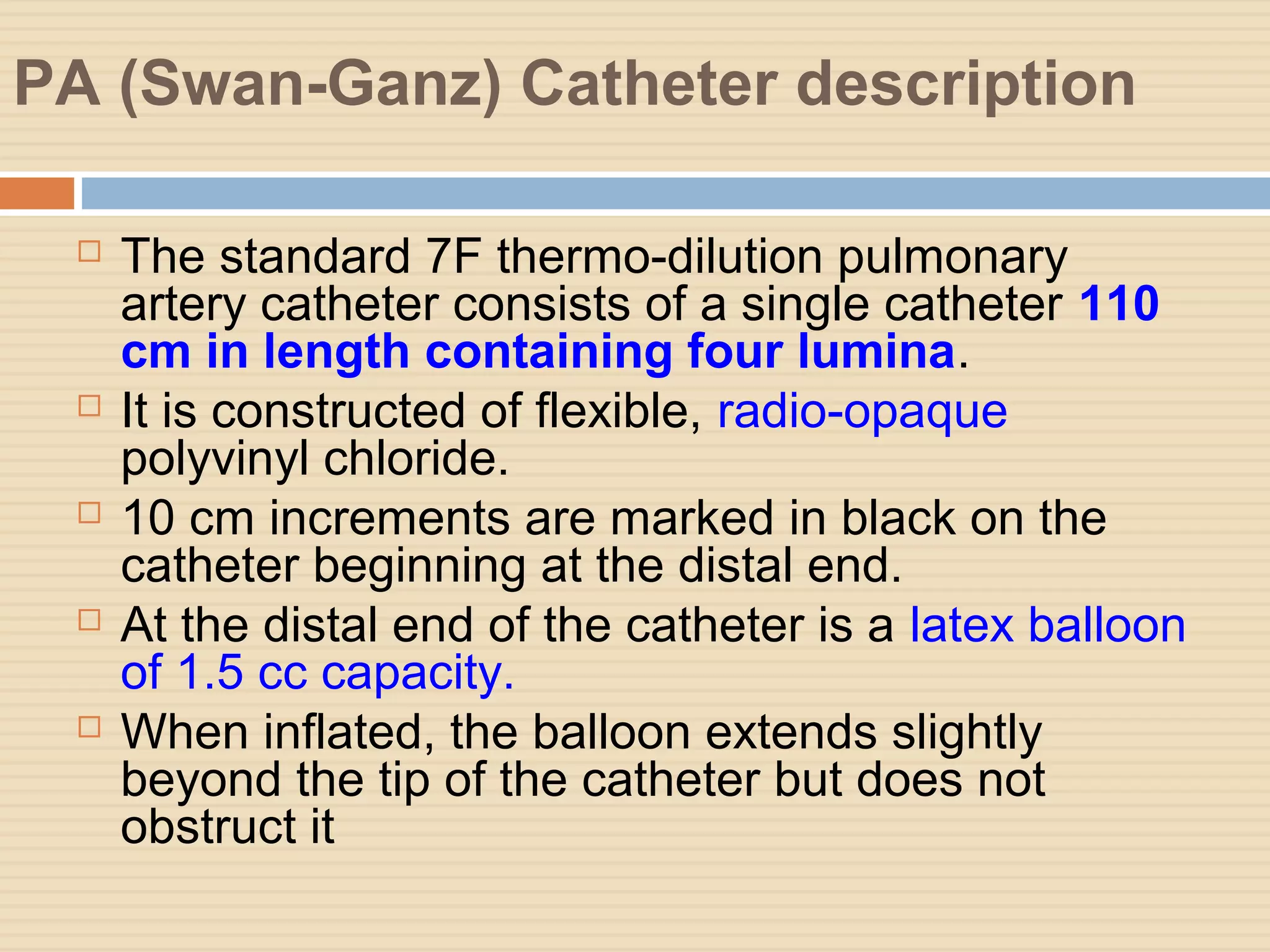
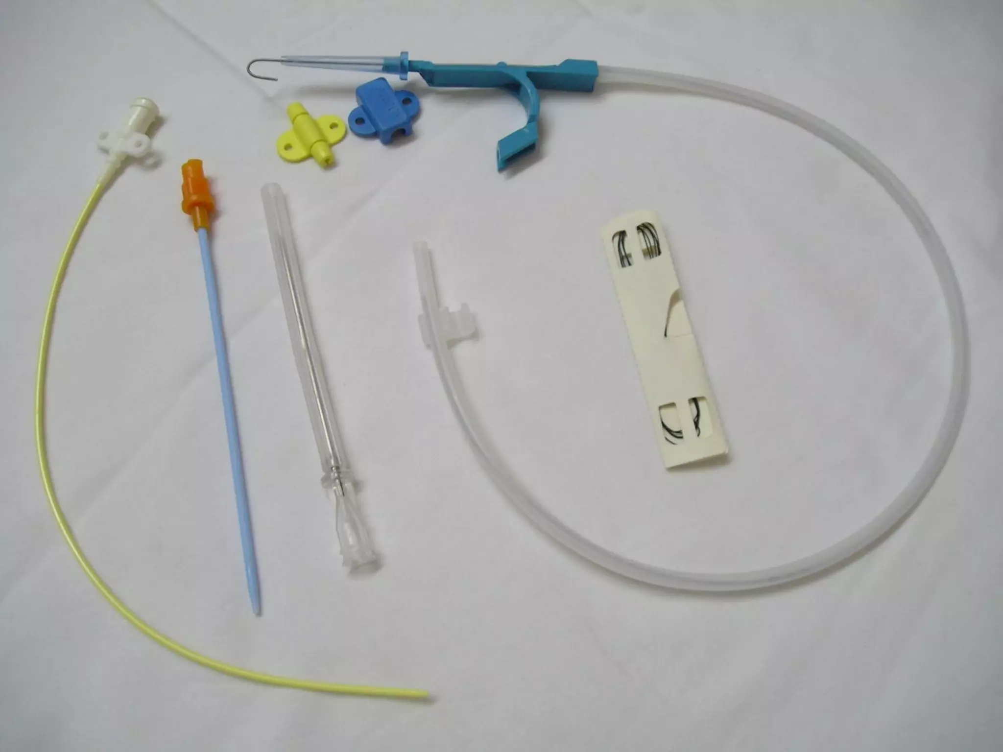
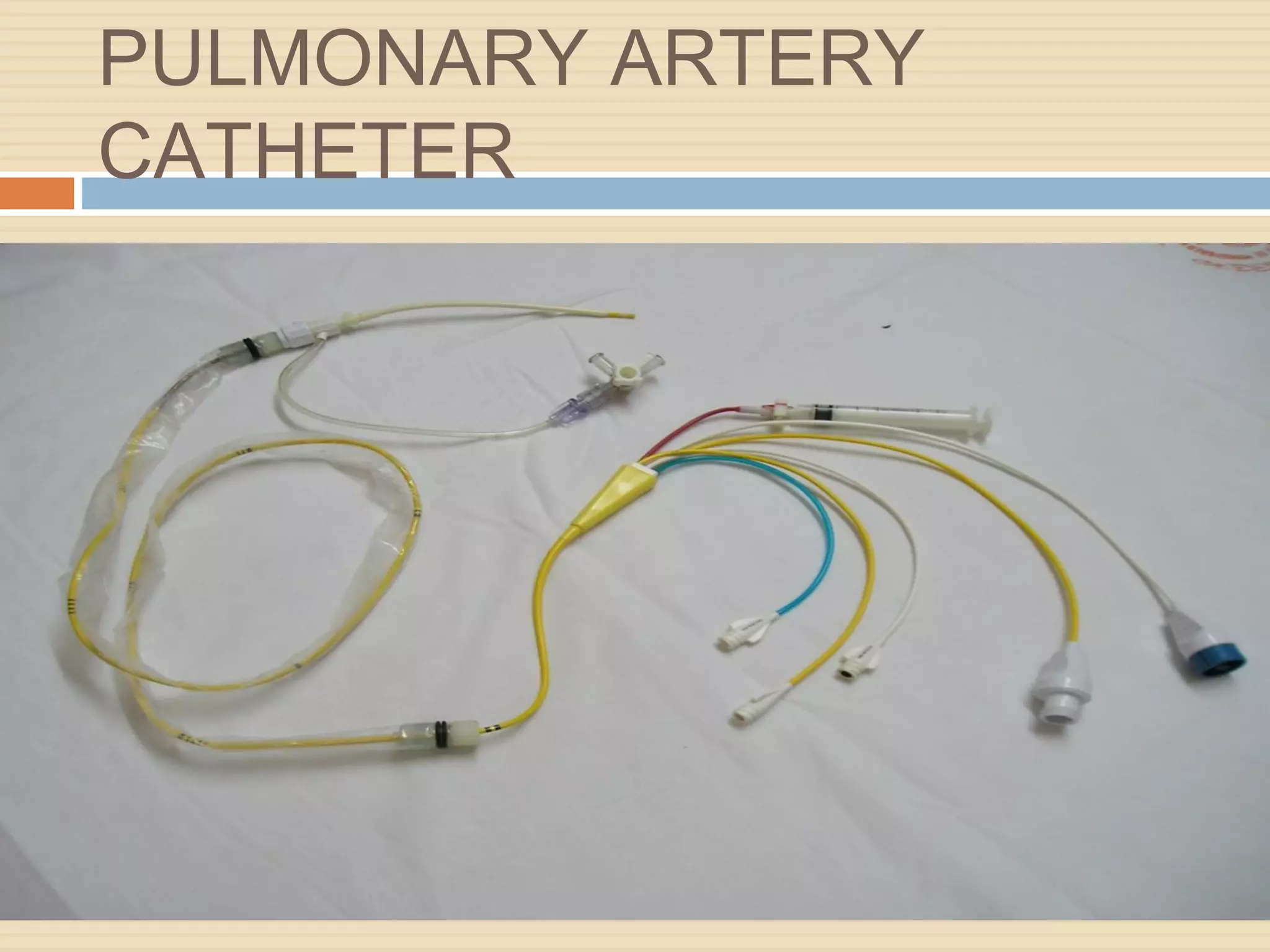


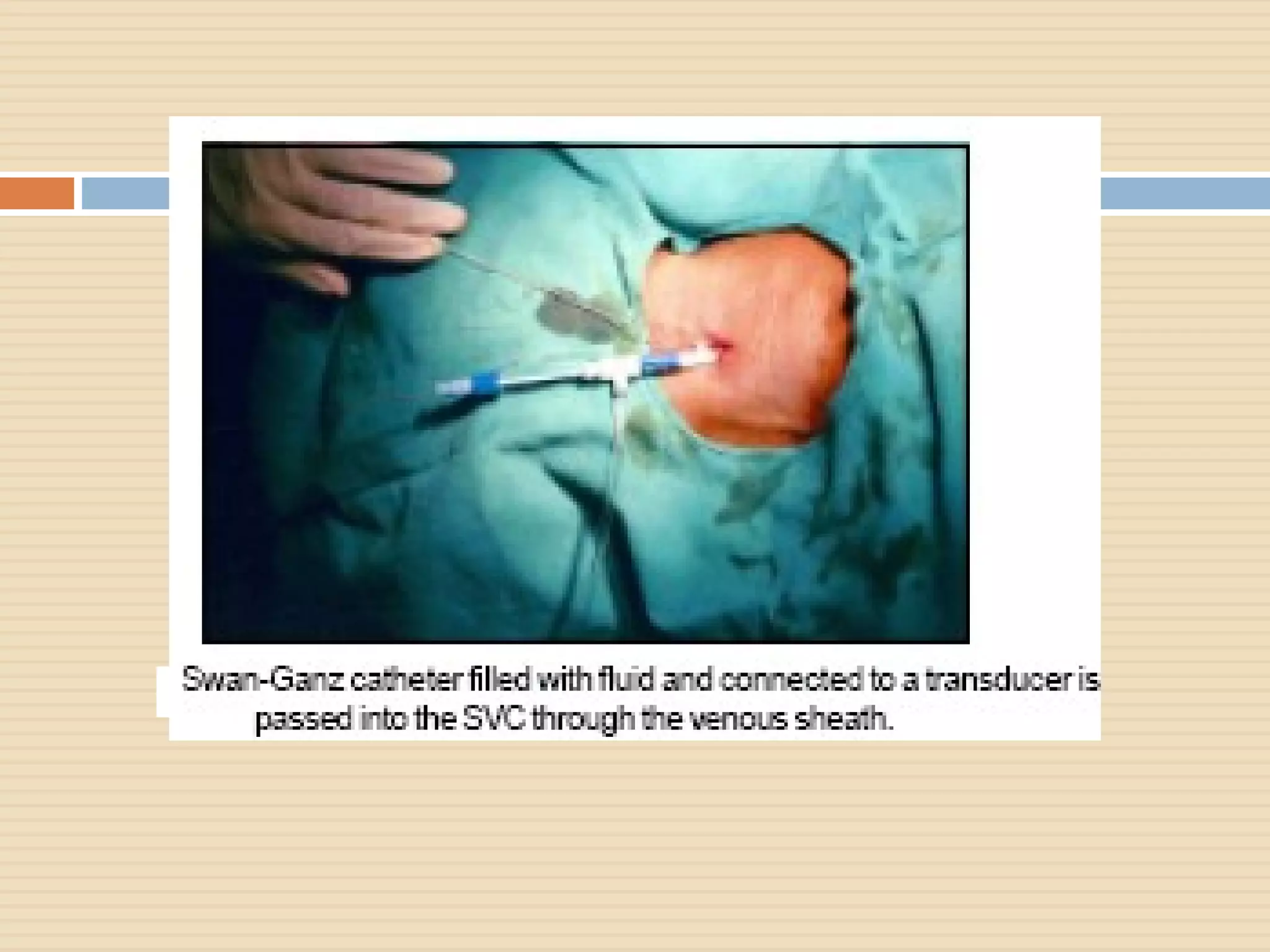
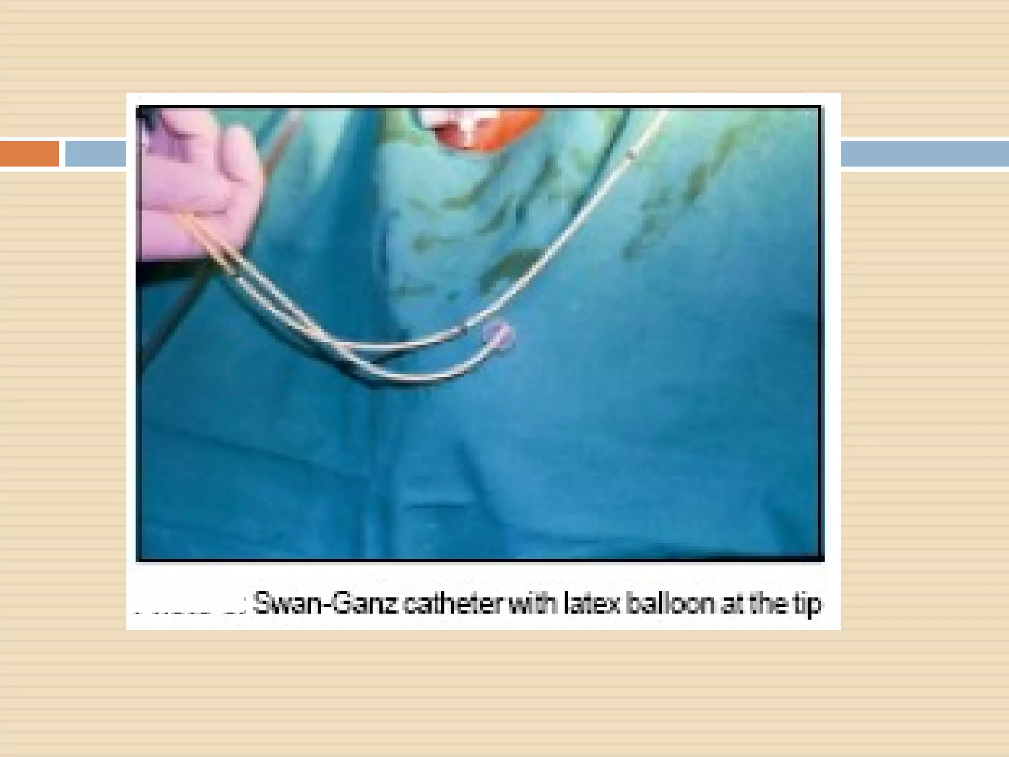


The document outlines various aspects of clinical monitoring in the ICU, focusing on techniques such as blood pressure monitoring, central venous pressure monitoring, and pulmonary artery pressure monitoring. It details the equipment required, procedures, complications, and the significance of these monitoring methods in assessing patient hemodynamics. Additionally, it discusses the interpretation of monitoring data to guide therapeutic decisions and the potential complications associated with invasive monitoring techniques like central venous catheterization.


![Clinicalteaching [autosaved]](https://cdn.slidesharecdn.com/ss_thumbnails/clinicalteachingautosaved-180718063103-thumbnail.jpg?width=640&height=640&fit=bounds)


