kinematics of machines-VTU Notes
•
8 likes•3,571 views

1. The document discusses various mechanisms including quick return motion mechanisms, straight line motion mechanisms, intermittent motion mechanisms, and steering gear mechanisms. 2. Specific mechanisms covered include the drag link mechanism, Whitworth mechanism, crank and slotted lever mechanism, Peaucellier's mechanism, Geneva wheel mechanism, ratchet and pawl mechanism, and Ackerman steering gear mechanism. 3. Key aspects of each mechanism such as their working principles, components, and applications are described.

Recommended
More Related Content
What's hot
What's hot (20)
Similar to kinematics of machines-VTU Notes
Similar to kinematics of machines-VTU Notes (20)
Recently uploaded
Recently uploaded (20)
kinematics of machines-VTU Notes
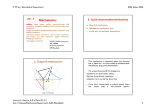
- 1. IV 'B' Sec Mechanical Department KOM Notes-2016 Santosh A. Goudar, B.E M.Tech (Ph.D.,) Asst. Professor,Mechanical Department, AIET, Moodbidri 1 Mechanisms: Syllabus: Quick return motion mechanisms-Drag link mechanism, Whitworth mechanism and Crank and slotted lever Mechanism. Straight line motion mechanisms Peaucellier's mechanism and Robert's mechanism. Intermittent Motion mechanisms -Geneva wheel mechanism and Ratchet and Pawl mechanism. Toggle mechanism, Pantograph, Ackerman steering gear mechanism UNIT - 2 SantoshA Goudar,B.E,M.Tech,(Ph.D)., Asst.Professor, MechanicalDepartment, AIET,Moodbidri 1 1. Quick return motion mechanisms a. Drag link mechanism, b. Whitworth mechanism and c. Crank and slotted lever Mechanism 2 a. Drag link mechanism 3 • This mechanism is obtained when the shortest link is fixed and it is also called as double-crank- mechanism, drag crank mechanism. • The unique features of this linkage are (a) there is no dead-centre phase, (b) Links 2 and 4 both rotate and (c) either 2 or 4 can be the driver link • If the link-2 rotates with a uniform speed, link-4 will rotate with a non-uniform speed. 4
- 2. IV 'B' Sec Mechanical Department KOM Notes-2016 Santosh A. Goudar, B.E M.Tech (Ph.D.,) Asst. Professor,Mechanical Department, AIET, Moodbidri 2 • When the point C moves through the Arc C'CC" the link-4 moves through 180° whereas Link-2 has moved through an angle 'α'. • However, if the link-4 further moves from point C" to C' it covers 180°, whereas the link-2 moves through an angle 'β'. • Since the angle 'α' is much larger than 'β' it is evident that even when link-4 has moved through the same angle i.e. 180° in both the cases 5 b. Whitworth mechanism 6 • When the driving crank CA moves from the position CA1 to CA2 (or the link DP from the position DP1 to DP2) through an angle α in the clockwise direction, the tool moves from the left hand end of its stroke to the right hand end. • Now when the driving crank moves from the position CA2 to CA1 (or the link DP from DP2 to DP1 ) through an angle β in the clockwise direction, the tool moves back from right hand end of its stroke to the left hand end. 7 • The time taken during the left to right movement of the ram (i.e. during forward or cutting stroke) will be equal to the time taken by the driving crank to move from CA1 to CA2. Similarly, the time taken during the right to left movement of the ram (or during the idle or return stroke) will be equal to the time taken by the driving crank to move from CA2 to CA1. 8
- 3. IV 'B' Sec Mechanical Department KOM Notes-2016 Santosh A. Goudar, B.E M.Tech (Ph.D.,) Asst. Professor,Mechanical Department, AIET, Moodbidri 3 • Since the crank link CA rotates at uniform angular velocity therefore time taken during the cutting stroke (or forward stroke) is more than the time taken during the return stroke. • Quick return ratio: The ratio between the time taken during the cutting and return strokes is given by, • This mechanism is mostly used in shaping and slotting machines. 9 c. Crank and slotted lever Mechanism 10 • In this mechanism link 3 is fixed. The slider (link 1) reciprocates in oscillating slotted lever (link 4) and crank (link 2) rotates. • The ram with the cutting tool reciprocates perpendicular to the fixed link 3 and AP1 and AP2 are extreme positions. • The forward or cutting stroke occurs when the crank rotates from the position CB1 to CB2 (or through an angle β) in the clockwise direction. • The return stroke occurs when the crank rotates from the position CB2 to CB1 (or through angle α) in the clockwise direction. 11 • Since the crank has uniform angular speed, therefore, • Since the tool travels a distance of R1 R2 during cutting and return stroke, therefore Length of stroke 12
- 4. IV 'B' Sec Mechanical Department KOM Notes-2016 Santosh A. Goudar, B.E M.Tech (Ph.D.,) Asst. Professor,Mechanical Department, AIET, Moodbidri 4 Straight line motion mechanisms • The mechanisms that permits only relative motion of an oscillatory nature along a straight line. The mechanisms used for this purpose are called straight line mechanisms. • There are mainly two types of Straight line motion mechanisms. 13 1. Exact straight line motion a. Peaucellier mechanism. b. Hart’s mechanism. c. Scott Russell’s Mechanism 2. Approximate straight line motion a. Watt’s mechanism. b. Modified Scott-Russel mechanism c. Grasshopper mechanism d. Tchebicheff’s mechanism. e. Roberts mechanism 14 Condition for generating Exact straight line motion • Let O be a point on the circumference of a circle of diameter OP • Let OA be any chord and B is a point on OA produced, such that OA × OB = constant • Then the locus of a point B will be a straight line perpendicular to the diameter OP 15 Proof: Draw BQ perpendicular to OP produced. Join AP. The triangles OAP and OQB are similar. But OP is constant as it is the diameter of a circle, therefore, if OA × OB is constant, then OQ will be constant. Hence the point B moves along the straight path BQ which is perpendicular to OP. 16
- 5. IV 'B' Sec Mechanical Department KOM Notes-2016 Santosh A. Goudar, B.E M.Tech (Ph.D.,) Asst. Professor,Mechanical Department, AIET, Moodbidri 5 Peaucellier mechanism. 17 • It consists of a fixed link OO1 and the other straight links O1A, OC, OD, AD, DB, BC and CA are connected by turning pairs at their intersections • The pin at A is constrained to move along the circumference of a circle with the fixed diameter OP, by means of the link O1A • In Fig., AC = CB = BD = DA ; OC = OD ; and OO1 = O1A 18 PROOF: • It may be proved that the product OA × OB remains constant, when the link O1A rotates. • Join CD to bisect AB at R. • Now from right angled triangles ORC and BRC, we have, 19 Since OC and BC are of constant length, therefore the product OB × OA remains constant. Hence the point B traces a straight path perpendicular to the diameter OP. 20
- 6. IV 'B' Sec Mechanical Department KOM Notes-2016 Santosh A. Goudar, B.E M.Tech (Ph.D.,) Asst. Professor,Mechanical Department, AIET, Moodbidri 6 Robert's mechanism 21 • It is also a four bar chain mechanism, which, in its mean position, has the form of a trapezium. • In fig., OO1 is fixed, OA=O1B , AP= PB, PQ is perpendicular to AB, and here Q is tracing point • If the mechanism is displaced as shown by the dotted lines in Fig., the point Q will trace out an approximately straight line 22 Intermittent Motion mechanisms 1. Geneva wheel mechanism 2. Ratchet and Pawl mechanism 23 1. Geneva wheel mechanism 2 1 24
- 7. IV 'B' Sec Mechanical Department KOM Notes-2016 Santosh A. Goudar, B.E M.Tech (Ph.D.,) Asst. Professor,Mechanical Department, AIET, Moodbidri 7 • A Geneva mechanism translates a continues rotation into an intermittent rotary motion . • A Geneva wheel consists of a driving wheel 1 carrying a pin P which engages in a slot of driven member 2 as shown in figure. • A member 2 is turned 1/4th of revolution for each rotation of plate1 • The angle β is half the angle turned through by member 2 during indexing period • This mechanism is used in preventing over winding of main spring in clock and watch 25 2. Ratchet and Pawl mechanism 2- Ratchet Wheel 3 – Driving Pawl 4 – Pawl Lever 5- Supplementary Pawl 26 • This mechanism is used to produce intermittent circular motion from oscillating member. • A ratchet consists of ratchet wheel, driving pawl shown in fig. • The driving pawl is held against the wheel by a spring or gravity. • As the pawl lever is raised, the driving pawl drives the wheel in counter-clockwise rotation. • A supplementary pawl is used to prevent the ratchet from reversing. • Ratchets are used in feed mechanisms, lifting jacks, clocks, watches and counting devices. 27 Steering Gear Mechanism • The steering gear mechanism is used for changing the direction of two or more of the wheel axles with reference to the chassis, so as to move the automobile in any desired path. • In automobiles, the front wheels are placed over the front axle & The back wheels are placed over the back axle • The steering is done by means of front wheels only, The back wheels remain straight and do not turn 28
- 8. IV 'B' Sec Mechanical Department KOM Notes-2016 Santosh A. Goudar, B.E M.Tech (Ph.D.,) Asst. Professor,Mechanical Department, AIET, Moodbidri 8 29 • In order to avoid skidding, the two front wheels must turn about the same instantaneous centre ‘I’ which lies on the axis of the back wheels. Condition for correct steering: • The condition for correct steering is that all the four wheels must turn about the same instantaneous centre. • While turning to the left side, axes of the front and the rear wheels meet at ‘I’. 30 Let, a = Wheel track, b = Wheel base c = Distance between the pivots A and B of the front axle Θ=The angle by which the inner wheel is turned; φ=The angle by which the outer wheel is turned; (Θ > φ), 31 This is the fundamental equation for correct steering. If this condition is satisfied, there will be no skidding of the wheels, when the vehicle takes a turn 32
- 9. IV 'B' Sec Mechanical Department KOM Notes-2016 Santosh A. Goudar, B.E M.Tech (Ph.D.,) Asst. Professor,Mechanical Department, AIET, Moodbidri 9 Ackerman steering gear mechanism 33 Ackerman steering gear taking left turn. 34 • In Ackerman steering gear, the mechanism ABCD is a four bar crank chain, as shown in Fig. • The shorter links BC and AD are of equal length and are connected by hinge joints with front wheel axles. The longer links AB and CD are of unequal length. • The following are the only three positions for correct steering. 1. When the vehicle moves along a straight path, the longer links AB and CD are parallel and the shorter links BC and AD are equally inclined to the longitudinal axis of the vehicle, as shown by firm lines in Fig. 35 2. When the vehicle is steering to the left, the position of the gear is shown by dotted lines in Fig.. In this position, the lines of the front wheel axle intersect on the back wheel axle at I, for correct steering 3. When the vehicle is steering to the right, the similar position may be obtained. • In order to satisfy the fundamental equation for correct steering (cot φ – cot θ = c / b) , the links AD and DC are suitably proportioned. • The value of θ and φ may be obtained either graphically or by calculations. 36 θ φ - Edited by Foxit Reader Copyright(C) by Foxit Corporation,2005-2009 For Evaluation Only.
- 10. IV 'B' Sec Mechanical Department KOM Notes-2016 Santosh A. Goudar, B.E M.Tech (Ph.D.,) Asst. Professor,Mechanical Department, AIET, Moodbidri 10 Toggle mechanism 37 tan2 F P Or 38 Pantograph • A pantograph is an instrument used to reproduce to an enlarged or a reduced scale and as exactly as possible the path described by a given point 39 • It consists of a jointed parallelogram ABCD as shown in Fig. It is made up of bars connected by turning pairs. • The bars BA and BC are extended to O and E respectively, such that OA/OB = AD/BE • Thus, for all relative positions of the bars, the triangles OAD and OBE are similar and the points O, D and E are in one straight line 40
- 11. IV 'B' Sec Mechanical Department KOM Notes-2016 Santosh A. Goudar, B.E M.Tech (Ph.D.,) Asst. Professor,Mechanical Department, AIET, Moodbidri 11 • It may be proved that point E traces out the same path as described by point D. • From similar triangles OAD and OBE, we find that OD/OE = AD/BE • Let point O be fixed and the points D and E move to some new positions D′ and E′. Then OD/OE = OD′/OE′ • A little consideration will show that the straight line DD′ is parallel to the straight line EE′. 41 • if E is constrained to move in a straight line, then D will trace out a straight line parallel to the former. • A pantograph is mostly used for the reproduction of plane areas and figures such as maps, plans etc., on enlarged or reduced scales. It is also used to guide cutting tools 42