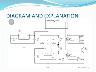
LIST OF CONTENT
1.INTRODUCTION
2.ABSTRACT
3.WORKING
4.CIRCUIT DIAGRAM
5.COMPONENTS
6.CONCLUSION
ABSTRACT
Automobiles have been the primary mode of transportation for
most of us and we depend on them for our day to day commute.
Brake failure indicator circuit is a circuit that constantly monitore the
condition of brake.The sensor which is attached to the circuit of a
brake failure by monitoring the brake switch and reminds you the
condition of brake every time when brake is appiled.
This mechanism involves a Brake wire which runs from the brake
lever to the braking mechanism set-up of the vehicle. It is this wire that
gets pulled when we apply brakes to stop our vehicle
INTRODUCTION
In brake failure indicator, when the brake is
applied
The gree LED blinks and the buzzer beeps for one
second and if the brake fails, the buzzer stop beeping.
Thus the buzzer function as an indicator of the brake
failure. Brake failure indicator is a device which is used to
avoid accidents.
It is a fully equipped and designed respectively for
automobile vehicles and this forms an integral part of
best quality of the vehicles. This product underwent
strenuous test in our automobile vehicles and it is good
WORKING
WORKING OF THIS BRAKE FAILURE CIRCUIT:
 Once the connection is made power the circuit, make sure
the Brake cable (here I have used a normal yellow wire to
represent the brake cable) is connected across the +5V and
base of BC557 through a resistor as shown in the circuit.
 If everything works as expected you should see the Green
LED turned on and the Buzzer and Red Light Turned Off.
Now, cut/remove the brake cable the Red LED and the Buzzer
should start flashing as shown in the video below.
DIAGRAM AND EXPLANATION
COMPONENTS
 PNP TRANSISTOR
 BUZZER
 RED AND GREEN COLOUR LED
 RESISTORS
 BATTERY
 BREAD BORD
 CAPACITORS
 555 TIMER
TRANSISTOR:
It is semiconductor device used to amplify or switch electrnic signal
and electrical power
BC557 is a PNP transistor hence the collector and emitter will be closed
(Forward biased) when the base pin is held at ground and will be
opened (Reverse biased) when a signal is provided to base pin. This is
where a PNP transistor differs from a NPN transistor, a Logic state (blue
colour) is used to toggle between Ground and Signal Voltage.
BUZZER:
 A buzzer is an audio signalling device,which may be
mechanical, electromechanical, or piezoelectric (piezo
for short). Typical uses of buzzers and beepers include
alarm devices, timers, and confirmation of user input
such as a mouse click or keystroke
LED
 A light-emitting diode (LED) is a two-lead
semiconductor light source. It is a p–n junction diode
that emits light when activated.
RESISTOR
 A resistor is a passive two-terminal electrical component that
Implements electrical resistance as a circuit element. In electronic
circuits, Resistors are used to reduce current flow, adjust signal levels,
to divide Voltages, bias active elements, and terminate transmission
lines, among other uses. High-power resistors that can dissipate many
watts of Electrical power as heat, may be used as part of motor
controls, in power Distribution systems, or as test loads for generators.

BATTERY
 An electric battery is device consisting of one or more
electro chemical cells with an external connections
provided to power electrical devices such as smart
phone, torch lights, electric cars ..etc.
BREAD BOARD
 The breadboard does not require soldering, it is reusable.
This makes it easy to use for creating temporary prototypes
and experimenting with circuit design. For this reason,
solderless breadboards are also extremely popular with
students and in technological education. A variety of
electronic systems may be prototyped by using
breadboards, from small analog and digital circuits to
complete central processing units (CPUs).
CAPACITOR
 A capacitor is a passive two-terminal electrical component
that stores potential energy y in an electric field. The effect
of a capacitor is known as capacitance. While some
capacitance exists between any two electrical conductors in
proximity in a circuit,a capacitor is a component designed
to add capacitance to a circuit. The capacitor was originally
known as a condenser.
555 TIMER
 The Astable mode in a 555 timer is mainly used for Blinking
LEDs or to do some periodic Turn On and Turn off actions. In
this project we have configures
the Timer to work with 0.3Sec on
time and 0.3sec Off time. The
value of the resistors R1, R2
and capacitor C1 decides
the on and off time of the
Pulse produced.
ADVANTAGES :
 No need of external battery. Circuit can be powered from the
vehicle’s battery itself.
 Power consumption is comparably less.
 It is not depend on the petrol level.
 Operating principle is very easy.
 Installation is simplified very much.
 The safety of driver is ensured.
 Brake failure is notified to the surrounding traffic via buzzer.
 The cost is low
APPLICATIONS
 Four wheeler application
 Two wheeler application
 Mechanical Crane
 Mechanical machines
CONCLUSION:
Brake failure indicator is a early warning system. it
constantly monitors the condition of the brake and
give audio visual indication.
Ppt on brake failure indicator.

Ppt on brake failure indicator.

  • 3.
  • 4.
    ABSTRACT Automobiles have beenthe primary mode of transportation for most of us and we depend on them for our day to day commute. Brake failure indicator circuit is a circuit that constantly monitore the condition of brake.The sensor which is attached to the circuit of a brake failure by monitoring the brake switch and reminds you the condition of brake every time when brake is appiled. This mechanism involves a Brake wire which runs from the brake lever to the braking mechanism set-up of the vehicle. It is this wire that gets pulled when we apply brakes to stop our vehicle
  • 5.
    INTRODUCTION In brake failureindicator, when the brake is applied The gree LED blinks and the buzzer beeps for one second and if the brake fails, the buzzer stop beeping. Thus the buzzer function as an indicator of the brake failure. Brake failure indicator is a device which is used to avoid accidents. It is a fully equipped and designed respectively for automobile vehicles and this forms an integral part of best quality of the vehicles. This product underwent strenuous test in our automobile vehicles and it is good
  • 6.
    WORKING WORKING OF THISBRAKE FAILURE CIRCUIT:  Once the connection is made power the circuit, make sure the Brake cable (here I have used a normal yellow wire to represent the brake cable) is connected across the +5V and base of BC557 through a resistor as shown in the circuit.  If everything works as expected you should see the Green LED turned on and the Buzzer and Red Light Turned Off. Now, cut/remove the brake cable the Red LED and the Buzzer should start flashing as shown in the video below.
  • 7.
  • 8.
    COMPONENTS  PNP TRANSISTOR BUZZER  RED AND GREEN COLOUR LED  RESISTORS  BATTERY  BREAD BORD  CAPACITORS  555 TIMER
  • 9.
    TRANSISTOR: It is semiconductordevice used to amplify or switch electrnic signal and electrical power BC557 is a PNP transistor hence the collector and emitter will be closed (Forward biased) when the base pin is held at ground and will be opened (Reverse biased) when a signal is provided to base pin. This is where a PNP transistor differs from a NPN transistor, a Logic state (blue colour) is used to toggle between Ground and Signal Voltage.
  • 10.
    BUZZER:  A buzzeris an audio signalling device,which may be mechanical, electromechanical, or piezoelectric (piezo for short). Typical uses of buzzers and beepers include alarm devices, timers, and confirmation of user input such as a mouse click or keystroke
  • 11.
    LED  A light-emittingdiode (LED) is a two-lead semiconductor light source. It is a p–n junction diode that emits light when activated.
  • 12.
    RESISTOR  A resistoris a passive two-terminal electrical component that Implements electrical resistance as a circuit element. In electronic circuits, Resistors are used to reduce current flow, adjust signal levels, to divide Voltages, bias active elements, and terminate transmission lines, among other uses. High-power resistors that can dissipate many watts of Electrical power as heat, may be used as part of motor controls, in power Distribution systems, or as test loads for generators. 
  • 13.
    BATTERY  An electricbattery is device consisting of one or more electro chemical cells with an external connections provided to power electrical devices such as smart phone, torch lights, electric cars ..etc.
  • 14.
    BREAD BOARD  Thebreadboard does not require soldering, it is reusable. This makes it easy to use for creating temporary prototypes and experimenting with circuit design. For this reason, solderless breadboards are also extremely popular with students and in technological education. A variety of electronic systems may be prototyped by using breadboards, from small analog and digital circuits to complete central processing units (CPUs).
  • 15.
    CAPACITOR  A capacitoris a passive two-terminal electrical component that stores potential energy y in an electric field. The effect of a capacitor is known as capacitance. While some capacitance exists between any two electrical conductors in proximity in a circuit,a capacitor is a component designed to add capacitance to a circuit. The capacitor was originally known as a condenser.
  • 16.
    555 TIMER  TheAstable mode in a 555 timer is mainly used for Blinking LEDs or to do some periodic Turn On and Turn off actions. In this project we have configures the Timer to work with 0.3Sec on time and 0.3sec Off time. The value of the resistors R1, R2 and capacitor C1 decides the on and off time of the Pulse produced.
  • 17.
    ADVANTAGES :  Noneed of external battery. Circuit can be powered from the vehicle’s battery itself.  Power consumption is comparably less.  It is not depend on the petrol level.  Operating principle is very easy.  Installation is simplified very much.  The safety of driver is ensured.  Brake failure is notified to the surrounding traffic via buzzer.  The cost is low
  • 18.
    APPLICATIONS  Four wheelerapplication  Two wheeler application  Mechanical Crane  Mechanical machines
  • 19.
    CONCLUSION: Brake failure indicatoris a early warning system. it constantly monitors the condition of the brake and give audio visual indication.