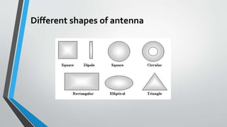
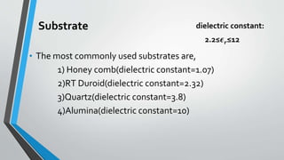
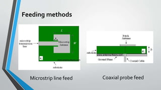
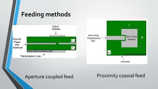
Microstrip Patch Antenna
Presented by,
A.Priyanka
Patch Antenna
TopView of Patch Antenna Side view of Patch Antenna
Different shapes of antenna
Substrate
• The most commonly used substrates are,
1) Honey comb(dielectric constant=1.07)
2)RT Duroid(dielectric constant=2.32)
3)Quartz(dielectric constant=3.8)
4)Alumina(dielectric constant=10)
dielectric constant:
2.2≤𝝐 𝒓≤12
Feeding methods
Coaxial probe feedMicrostrip line feed
Feeding methods
Proximity coaxial feedAperture coupled feed
Comparing different feed techniques
Rectangular Patch Antenna
• The length of the patch is:
𝜆0
3
< 𝐿 <
𝜆0
2
• At low frequencies, initial vales of 𝝐 𝒓eff. referred to as the static values and are
given by:
𝝐 𝒓eff. =
𝝐 𝒓
+1
2
+
𝝐 𝒓
−1
2
[1+
12ℎ
𝑤
]-1/2
Where,
h= height of substrate
w= width of the patch
Rectangular Patch Antenna
• For an efficient radiator, practical width that leads to good radiator
efficiencies is:
W =
1
2𝑓𝑟 𝜇0
𝜖0
2
𝜖 𝑟
+1
=
𝑣0
2𝑓𝑟
2
𝜖 𝑟
+1
• For normalized extension of length:
∆𝐿
ℎ
= 0.412
(𝝐 𝒓eff.+0.3)(
𝑊
ℎ
+0.264)
(𝝐 𝒓eff.−0.258)(
𝑊
ℎ
+0.8)
Where,v0= free space velocity of light
Rectangular Patch Antenna
• Directivity of the single patch is:
D0 = {5. 2dB W<<𝜆0
4(
𝑊
𝜆0
) W>>𝜆0
• Finally, the effective length of the patch is:
Leff. = L+2 ∆𝐿
Where, ∆𝐿= extended length of the patch
Rectangular Patch Antenna
• The actual length of the patch can be determined by solving:
L =
1
2𝑓𝑟 𝝐 𝒓eff. 𝜇0
𝜖0
- 2 ∆𝐿
• Finally, the effective length of the patch is:
Leff. = L+2 ∆𝐿
Where, ∆𝐿= extended length of the patch
Remedies:
• Low power and low gain can overcome by arrays
configuration.
•The band width can increase up to 60% by using some
special techniques.
•Surface wave associated limitations such as poor
efficiency,increased mutual coupling , reduced gain and
radiation pattern can overcome.
Thank you

Microstrip patch

  • 1.
  • 2.
    Patch Antenna TopView ofPatch Antenna Side view of Patch Antenna
  • 3.
  • 4.
    Substrate • The mostcommonly used substrates are, 1) Honey comb(dielectric constant=1.07) 2)RT Duroid(dielectric constant=2.32) 3)Quartz(dielectric constant=3.8) 4)Alumina(dielectric constant=10) dielectric constant: 2.2≤𝝐 𝒓≤12
  • 5.
    Feeding methods Coaxial probefeedMicrostrip line feed
  • 6.
    Feeding methods Proximity coaxialfeedAperture coupled feed
  • 7.
  • 8.
    Rectangular Patch Antenna •The length of the patch is: 𝜆0 3 < 𝐿 < 𝜆0 2 • At low frequencies, initial vales of 𝝐 𝒓eff. referred to as the static values and are given by: 𝝐 𝒓eff. = 𝝐 𝒓 +1 2 + 𝝐 𝒓 −1 2 [1+ 12ℎ 𝑤 ]-1/2 Where, h= height of substrate w= width of the patch
  • 9.
    Rectangular Patch Antenna •For an efficient radiator, practical width that leads to good radiator efficiencies is: W = 1 2𝑓𝑟 𝜇0 𝜖0 2 𝜖 𝑟 +1 = 𝑣0 2𝑓𝑟 2 𝜖 𝑟 +1 • For normalized extension of length: ∆𝐿 ℎ = 0.412 (𝝐 𝒓eff.+0.3)( 𝑊 ℎ +0.264) (𝝐 𝒓eff.−0.258)( 𝑊 ℎ +0.8) Where,v0= free space velocity of light
  • 10.
    Rectangular Patch Antenna •Directivity of the single patch is: D0 = {5. 2dB W<<𝜆0 4( 𝑊 𝜆0 ) W>>𝜆0 • Finally, the effective length of the patch is: Leff. = L+2 ∆𝐿 Where, ∆𝐿= extended length of the patch
  • 11.
    Rectangular Patch Antenna •The actual length of the patch can be determined by solving: L = 1 2𝑓𝑟 𝝐 𝒓eff. 𝜇0 𝜖0 - 2 ∆𝐿 • Finally, the effective length of the patch is: Leff. = L+2 ∆𝐿 Where, ∆𝐿= extended length of the patch
  • 12.
    Remedies: • Low powerand low gain can overcome by arrays configuration. •The band width can increase up to 60% by using some special techniques. •Surface wave associated limitations such as poor efficiency,increased mutual coupling , reduced gain and radiation pattern can overcome.
  • 13.