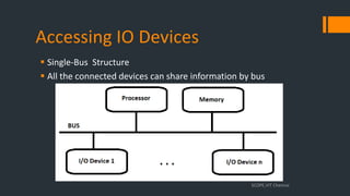
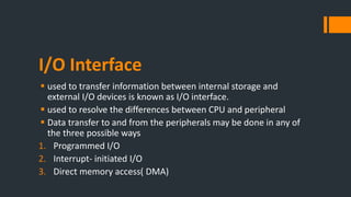
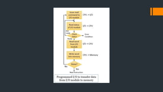
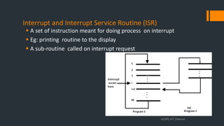
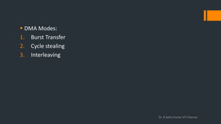
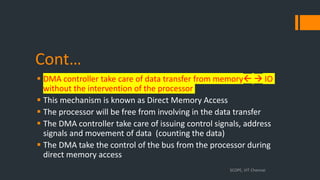
Module 6
I/O Interfacing and Communication
What is Interfacing?
 Interfacing is the process of connecting two different systems or devices
to enable communication between them.
 In the context of computer systems, interfacing typically involves
connecting various hardware components, such as the central
processing unit (CPU), memory, input/output devices (I/O), and storage
devices
 The computer system’s I/O architecture is its interface to the outside
world.
 This architecture provides a systematic means of controlling interaction
with the outside world and provides the operating system with the
information it needs to manage I/O activity effectively.
Dr. B Sathis Kumar VIT Chennai
I/O Bus and Interface module
• Transferring of
information between the
internal storage devices
i.e. memory and the
external peripheral (I/O)
devices
• Synchronization
• Buffering
• The I/O bus includes
data lines, address lines,
and control lines
• Each interface decodes
the control and address
received from the I/O
bus.
Buffering
Dr. B Sathis Kumar VIT Chennai
 A buffer is a data area
shared by hardware
devices or program
processes that operate
at different speeds or
with different sets of
priorities.
 The buffer allows each
device or process to
operate without being
held up by the other.
An interface receives any of the following four commands
 Control − A command control is given to activate the peripheral and to
inform its next task. This control command depends on the peripheral,
and each peripheral receives its sequence of control commands,
depending on its mode of operation.
 Status − A status command can test multiple test conditions in the
interface and the peripheral.
 Data Output − A data output command creates the interface counter
to the command by sending data from the bus to one of its registers.
 Data Input − The data input command is opposite to the data output
command. In data input, the interface gets an element of data from
the peripheral and places it in its buffer register
Dr. B Sathis Kumar VIT Chennai
Communication
Dr. B Sathis Kumar VIT Chennai
Handshaking
 In terms of the computer system also, it means somewhat the same. Through handshaking, a
communication link is established between two different components of a computer. This
communication is the transfer of data.
 So, in the handshaking process, first, a strobe signal is sent by the source channel to the
destination.
 Then, the destination sends back the acknowledgment that the signal has been received with
a signal informing whether the destination channel is free or not for receiving the data.
 By following these steps, communication is established between the sender and the receiver
ends and then the further transfer of data takes place within the two through the data bus.
 I/O transfers: Provides path
for data transfer from
Memory to I/O
 Manages I/O tasks from
external devices
 CPU sends the program, IOP
executes
 Fetch and executes the
instructions
Transmission
 Serial vs Parallel
Serial Transmission
Asynchronous tx – an extra bit is added to
each byte to alert the receiver to the arrival
of new data. 0 is used as a start bit, while 1
is used as a stop bit.
Synchronous tx– no extra bit is added to
each byte. Data is transferred in batches,
each of which contains multiple bytes.
1. Assume that each character code consists of 8 bits. The number
of characters that can be transmitted per second through
synchronous serial line at 2400 baud rate (one baud (one bit)), and
with two stop bits is
Baud rate: Rate at which data is transmitted
2. In parallel communication, if the time interval to transmit
one bit is 10μs. What is the time to transmit an 8-bit word?
DATA COMMUNICATION PROCESSOR
 A data communication processor is an I/O processor that
distributes and collects data from numerous remote terminals
connected through telephone and other communication lines
to the computer. It is a specialized I/O processor designed to
communicate with data communication networks.
 It also communicates with CPU and memory in the same manner
as any I/O processor does.
Dr. B Sathis Kumar VIT Chennai
Data Communication Processor
Simplex
Half duplex
Full Duplex
Accessing IO Devices
 Single-Bus Structure
 All the connected devices can share information by bus
SCOPE,VIT Chennai
INPUT/OUTPUT
 Exchange of data between the computer and other devices
 Interacting with computer using input/output devices
 Human operator: use keyboard to input data and views the output
on the display screen
 Computers communicate with other computer over the internet
 Exchanging data from/to the computer is the basic feature
SCOPE, VIT Chennai
INPUT/OUTPUT DEVICES
 Keyboard
 Mouse
 Digital Camera
 Scanners
 Joy stick
 Microphone
SCOPE, VIT Chennai
 Monitor
 Projector
 Printer
 Speaker
 Plotters
 Head Phones
I/O Interface
 used to transfer information between internal storage and
external I/O devices is known as I/O interface.
 used to resolve the differences between CPU and peripheral
 Data transfer to and from the peripherals may be done in any of
the three possible ways
1. Programmed I/O
2. Interrupt- initiated I/O
3. Direct memory access( DMA)
Programmed I/O
 Each data item transfer is initiated by an instruction in the program
 transfer is from a CPU register and memory
 constant monitoring by the CPU of the peripheral devices is necessary
 I/O device does not have direct access to the memory unit.
 A transfer from I/O device to memory requires the execution of several instructions
by the CPU, including an input instruction to transfer the data from device to the
CPU and store instruction to transfer the data from CPU to memory
 In programmed I/O, the CPU stays in the program loop until the I/O unit indicates
that it is ready for data transfer.
 This is a time consuming process since it needlessly keeps the CPU busy
Interrupt- initiated I/O
 In the previous case we saw the CPU is kept busy unnecessarily
 Using an interrupt driven method for data transfer avoids this
situation
 Whenever it is determined that the device is ready for data transfer it
initiates an interrupt request signal to the computer
 Meantime, the CPU can proceed for any other program execution.
 Upon detection of an external interrupt signal, the CPU stops
momentarily the task that it was already performing, branches to the
service program to process the I/O transfer, and then return to the
task it was originally performing.
Drawbacks
 Both require active intervention of the processor to transfer data
between memory and the I/O module
 The I/O transfer rate is limited by the speed with which the
processor can test and service a device.
 The processor is tied up in managing an I/O transfer; a number of
instructions must be executed for each I/O transfer.
Direct Memory Access (DMA)
 The data transfer between a fast storage media such as magnetic disk and
memory unit is limited by the speed of the CPU
 DMA allows the peripherals directly communicate with each other using the
memory buses, removing the intervention of the CPU
 During DMA the CPU is idle and it has no control over the memory buses
 The DMA controller takes over the buses to manage the transfer directly
between the I/O devices and the memory unit.
 DMA controller is a special purpose processor which controls data transfer
between memory and I/O as it generates address and control signals for
memory
 DMA could work even when a instruction is executing by the CPU
Dr. B Sathis Kumar VIT Chennai
Bus Request:DMA controller to request the CPU to relinquish
the control of the buses.
Bus Grant: It is activated by the CPU to Inform the external DMA
controller
I/O Processor
Interrupt and Interrupt Service Routine (ISR)
 A set of instruction meant for doing process on interrupt
 Eg: printing routine to the display
 A sub-routine called on interrupt request
SCOPE,VIT Chennai
Resuming to original process
 After the execution of the ISR the processor resumes the original
program and continue its execution
 The processor store the information (state) about the original
process before calling the ISR. This cause delay in executing ISR.
This delay is called as Interrupt Latency
 Most processors only save a minimal amount of data (state) like
program counter, Processor status registers and data registers
SCOPE,VIT Chennai
Handling Multiple Interrupting Devices
 Multiple independent I/O devices capable of generating interrupt
request could associated to the processor & main memory through
bus lines
 Every /any device can raise interrupt request at any time or any
two/more devices can raise interrupt request at the same time
 The processor has to know
 which device has generated an interrupt?
 which ISR should be executed?
 can other device interrupt the processor? ,while the processor is executing
ISR for some device
 To select the INT requests, If two INR are signaled at the same time
SCOPE,VIT Chennai
Cont..
 Over the single control line all the devices are connected to the
processor, how does the processor knows INT requested sending
device which are coupled to this common line
 The processor reads the status flags data available in the device
sending an interrupt request
 Every device's status register has an IRQ flag bit, which it sets to 1
when requesting an interrupt
 Simple way to identify the interrupting device is by having ISR poll on
all the connected devices
 The first encountered device with IRQ bit set should be serviced
 Disadvantage of polling: spending time to check the status bits of all
the devices
SCOPE,VIT Chennai
Vectored Interrupts
 A interrupting device inform special code to the processor to
identify itself
 The code/address points to the starting address of an ISR for that
device
 The bit size of the code may vary from 4-8 bits
 The processor can immediately start processing the ISR
 This scheme of handling interrupt is called as vectored Interrupts
SCOPE,VIT Chennai
Interrupt Priority
 I / O devices are grouped into priorities order
 The priority level is used. It range from high priority to low priority
devices
 The interrupt request from the high priority devices are served
first
 If two devices are sending IRQ at same time the processor resolve
by priority and selects the device with highest priority
 The priorities can be fixed one and programmable with privileged
instruction
SCOPE,VIT Chennai
Cont…
SCOPE,VIT Chennai
 DMA Modes:
1. Burst Transfer
2. Cycle stealing
3. Interleaving
Dr. B Sathis Kumar VIT Chennai
Burst Transfer
DMA returns the bus after complete data transfer.
Steps involved are:
Bus grant request time.
Transfer the entire block of data at transfer rate of device because the
device is usually slow than the speed at which the data can be transferred
to CPU.
Release the control of the bus back to CPU
Tx = Time required to prepare data
Ty = Time required to transfer data
% of time CPU is idle/blocked = Ty/(Tx+Ty) * 100
% of time CPU is busy = Tx/(Tx+Ty) * 100
Cycle Stealing
 An alternative method in which DMA controller transfers one word at a time
after which it must return the control of the buses to the CPU
 The CPU delays its operation only for one memory cycle to allow the direct
memory I/O transfer to “steal” one memory cycle.
 Steps Involved are:
1. Buffer the byte into the buffer
2. Inform the CPU that the device has 1 byte to transfer (i.e. bus grant
request)
3. Transfer the byte (at system bus speed)
4. Release the control of the bus back to CPU.
% of time CPU is idle/blocked = Ty/Tx * 100
 % of time CPU is busy = Tx/Ty * 100 Tx = Time required to prepare
data
Ty = Time required to transfer
Interleaving DMA
 The DMA controller takes over the system bus when the microprocessor is not
using it.
 CPU is not blocked due to DMA
 Maximum time required for data transfer
 Speed of data transfer : Burst mode > cycle stealing > interleaving
 Time taken?
BUS Arbitration
 Bus arbitration: The current bus master accesses and then leaves the control of the bus and
passes it to another bus requesting processor unit
 The controller that has access to a bus at an instance is known as a Bus master
 Why?
 DMA controllers or other controllers or processors try to access the common bus at the
same time. Access can be given to only one of those.
 Bus Arbitration procedure is implemented to coordinate the activities of all devices
requesting memory transfers.
Dr. B Sathis Kumar VIT Chennai
 Centralized bus arbitration
A single bus arbiter performs the required arbitration.
Distributed bus arbitration
All devices participating in the selection of the next bus master.
Dr. B Sathis Kumar VIT Chennai
 There are three bus arbitration methods:
1. Daisy Chaining method:
2. Polling or Rotating Priority method:
3. Fixed priority or Independent Request method
DCM: The bus grant signal serially propagates through each master
until it encounters the first one that is requesting access to the bus
and blocks BGT.
• The value of priority assigned to a device depends on the
position of the master bus.
• Propagation delay arises in this method.
• If one device fails then the entire system will stop working.
Dr. B Sathis Kumar VIT Chennai
 Rotating Priority:
The controller is utilized to produce the unique priority for the
master (or address).
It is challenging to add bus masters since it increases the
circuit's address line count.
Fixed Priority Method
Dr. B Sathis Kumar VIT Chennai
I/O Interfacing
Communication
• Serial Tx
• Parallel Tx
• Problems
• Simplex, Half
duplex full duplex
Programmed I/O
Interrupt- initiated I/O
Direct memory access( I/O
processor)
Multiple Interrupts
1. Vectored
2. Interrupt Priority
DMA
1. Burst transfer
2. One Cycle Stealing
3. Interleaving
There are three bus arbitration methods:
1. Daisy Chaining method:
2.Polling or Rotating Priority method:
3.Fixed priority or Independent Request method
Eg: Key Board & Display Interface
SCOPE,VIT Chennai
Cont…
 The interface consists of the following registers
 Data register (DATAIN & DATAOUT)
 Status Register consists of single bit status flag (SIN,SOUT,DIRQ,KIRQ)
 Control Register
SCOPE,VIT Chennai
Cont..
 SIN flag represents keyboard status
 SIN flag set to 1 when key is pressed(data is ready) and it get reset
when the processor had read the data
 SOUT flag represents display status
 Similar to SIN flag
 KIRQ ,DIRQ flag bits represent the interrupt to the processor( if 1
interrupt request is send to the processor, after the processor service
the interrupt request it get reset) by the Keyboard and Display
respectively
 DEN,KEN are control flag bits used to enable and disable the display
and the keyboard respectively
SCOPE,VIT Chennai
Interrupts
 In the programmed control led IO, the processor has to
continuously monitor the devices for any input/output data
 This process over burden the process to monitor the IO devices at
a regular an intervals
 An alternate approach to perform IO operation i.e. when the IO
devices are ready to transfer or receive the data then it can notify
the processor by means of interrupts
SCOPE,VIT Chennai
Cont…
 Interrupt is an hardware signal send by the peripherals to the
processor
 The processor no longer has to monitor the IO peripherals
 How the processor react for an Interrupt?
 In abstract, The processor pause its ongoing process execution, It
acknowledges the interrupting device and executes the Interrupt
Service Routine(ISR) ,after the execution of ISR the processor resumes
the execution of the ongoing process.
SCOPE,VIT Chennai
Interrupt Service Routine (ISR)
 A set of instruction meant for doing process on interrupt
 Eg: printing routine to the display
 A sub-routine called on interrupt request
SCOPE,VIT Chennai
Resuming to original process
 After the execution of the ISR the processor resumes the original
program and continue its execution
 The processor store the information (state) about the original
process before calling the ISR. This cause delay in executing ISR.
This delay is called as Interrupt Latency
 Most processors only save a minimal amount of data (state) like
program counter, Processor status registers and data registers
SCOPE,VIT Chennai
Interrupt Acknowledgement
 The processor informs the device about the recognition of the
interrupt
 Generally ,processor send an explicit ACK control signal
 By doing data transfer the processor informs the device
 INR signal , interrupt the executing program & Can alter the expected
events sequence
 These changes can often be unacceptable, and should not be permitted
 For example, the processor may not want the same device to interrupt
while executing its ISR
SCOPE,VIT Chennai
Interrupt Flag
 In general, the Processors allows to enable or disable such
interruptions as required
 Enabling/Disabling the Interrupt Flag
 The processor avoids interrupt request from devices while
executing the ISR by disabling the interrupt flag
 The processor gets ready to accept interrupt after the ISR by
enabling the Interrupt Flag
SCOPE,VIT Chennai
I/O Interface
 used to transfer information between internal storage and external
I/O devices is known as I/O interface.
 used to resolve the differences between CPU and peripheral
 Data transfer to and from the peripherals may be done in any of the
three possible ways
1. Programmed I/O
2. Interrupt- initiated I/O
3. Direct memory access( DMA)
SCOPE, VIT Chennai
Dr. B Sathis Kumar VIT Chennai
1. Programmed I/O
 Each data item transfer is initiated by an instruction in the program
 transfer is from a CPU register and memory
 constant monitoring by the CPU of the peripheral devices is necessary
 I/O device does not have direct access to the memory unit.
 A transfer from I/O device to memory requires the execution of several
instructions by the CPU, including an input instruction to transfer the
data from device to the CPU and store instruction to transfer the data
from CPU to memory
 In programmed I/O, the CPU stays in the program loop until the I/O unit
indicates that it is ready for data transfer.
 This is a time consuming process since it needlessly keeps the CPU busy
SCOPE, VIT Chennai
Dr. B Sathis Kumar VIT Chennai
2. Interrupt- initiated I/O
 In the previous case we saw the CPU is kept busy unnecessarily
 Using an interrupt driven method for data transfer avoids this
situation
 Whenever it is determined that the device is ready for data transfer
it initiates an interrupt request signal to the computer
 Meantime, the CPU can proceed for any other program execution.
 Upon detection of an external interrupt signal, the CPU stops
momentarily the task that it was already performing, branches to
the service program to process the I/O transfer, and then return to
the task it was originally performing.
SCOPE, VIT Chennai
Handling Multiple Interrupting Devices
 Multiple independent I/O devices capable of generating interrupt
request could associated to the processor & main memory through
bus lines
 Every /any device can raise interrupt request at any time or any
two/more devices can raise interrupt request at the same time
 The processor has to know
 which device has generated an interrupt?
 which ISR should be executed?
 can other device interrupt the processor? ,while the processor is executing
ISR for some device
 To select the INT requests, If two INR are signaled at the same time
SCOPE,VIT Chennai
Cont..
 Over the single control line all the devices are connected to the
processor, how does the processor knows INT requested sending
device which are coupled to this common line
 The processor reads the status flags data available in the device
sending an interrupt request
 Every device's status register has an IRQ flag bit, which it sets to 1
when requesting an interrupt
 Simple way to identify the interrupting device is by having ISR poll on
all the connected devices
 The first encountered device with IRQ bit set should be serviced
 Disadvantage of polling: spending time to check the status bits of all
the devices
SCOPE,VIT Chennai
Vectored Interrupts
 A interrupting device inform special code to the processor to
identify itself
 The code/address points to the starting address of an ISR for that
device
 The bit size of the code may vary from 4-8 bits
 The processor can immediately start processing the ISR
 This scheme of handling interrupt is called as vectored Interrupts
SCOPE,VIT Chennai
Interrupt Priority
 I / O devices are grouped into priorities order
 The priority level is used. It range from high priority to low priority
devices
 The interrupt request from the high priority devices are served
first
 If two devices are sending IRQ at same time the processor resolve
by priority and selects the device with highest priority
 The priorities can be fixed one and programmable with privileged
instruction
SCOPE,VIT Chennai
Cont…
SCOPE,VIT Chennai
a. Daisy Chaining – Priority Interrupt
Dr. B Sathis Kumar VIT Chennai
Daisy Chaining – Priority Interrupt
 Also called as serial chaining used to handle priority interrupt
 All devices connected based on their priority
 The highest priority is directly connected to the CPU’s INTACK signal
 INTACK sends 1 if any request sent
 If device has requested for access
1 is consumed and P0 = 0
else
1 is passed and P0 = 1
 This disables all the other low priority request
 That device generates the vectored address to CPU
Dr. B Sathis Kumar VIT Chennai
b. Parallel Chaining – Priority Interrupt
Dr. B Sathis Kumar VIT Chennai
Parallel Chaining – Priority Interrupt
 IST = 1 if any device has generated an interrupt
 IST = 0 if none of the devices have generated an interrupt
 IEN = 1 if CPU is ready to handle the interrupt
 IEN = 0 if CPU is not ready to handle the interrupt
 IST and IEN has to be 1 for CPU to handle interrupt
 This generates 1 from the INTACK
 These 3 enabled signals enable the VAD in CPU
Dr. B Sathis Kumar VIT Chennai
Drawbacks
 Both require active intervention of the processor to transfer data
between memory and the I/O module
 The I/O transfer rate is limited by the speed with which the
processor can test and service a device.
 The processor is tied up in managing an I/O transfer; a number of
instructions must be executed for each I/O transfer.
SCOPE, VIT Chennai
Direct Memory Access (DMA)
 The data transfer between a fast storage media such as magnetic
disk and memory unit is limited by the speed of the CPU
 DMA allows the peripherals directly communicate with each other
using the memory buses, removing the intervention of the CPU
 During DMA the CPU is idle and it has no control over the memory
buses
 The DMA controller takes over the buses to manage the transfer
directly between the I/O devices and the memory unit.
 DMA controller is a special purpose processor which controls data
transfer between memory and I/O as it generates address and
control signals for memory
 DMA could work even when a instruction is executing by the CPU
SCOPE, VIT Chennai
Centralized arbitration :Daisy Chain
SCOPE,VIT Chennai
Cont…
 DMA sends Bus Request (BR) to the processor
 If the processor is ready to grant access in responds to the BR , it sends Bus
grant (BG1) signal to the first connected DMA controller Informing that, it
may use the bus once it is free
 The DMA controller1 receives the acknowledgement from the processor. If
the DMA 1 had requested the bus it will become the bus master other
wise it will forward the acknowledgement to the next DMA with BG2 signal
 The mechanism of using acknowledgment if it belongs to requested one,
or else forwarding the acknowledgement to the next device is called as
Daisy Chain
 The processor sends Bus Busy signal to prevent other device to access the
bus
SCOPE,VIT Chennai
Cont…
 The processor has to do data transfer ,it sends address signal and
control signal.
 It has to wait for the memory , IO devices to complete the data
transfer ,expect the data transfer between register to register
 It burdens the processor i.e. more delay for waiting the IO devices
and memory
 It blocks the processor to execute the other instructions
 To over come this DMA controllers are used
SCOPE,VIT Chennai
Cont…
 DMA controller take care of data transfer from memory  IO
without the intervention of the processor
 This mechanism is known as Direct Memory Access
 The processor will be free from involving in the data transfer
 The DMA controller take care of issuing control signals, address
signals and movement of data (counting the data)
 The DMA take the control of the bus from the processor during
direct memory access
SCOPE, VIT Chennai
 THANK YOU
SCOPE, VIT Chennai

Module 6.pptx for computer architecture and organisation

  • 1.
    Module 6 I/O Interfacingand Communication
  • 2.
    What is Interfacing? Interfacing is the process of connecting two different systems or devices to enable communication between them.  In the context of computer systems, interfacing typically involves connecting various hardware components, such as the central processing unit (CPU), memory, input/output devices (I/O), and storage devices  The computer system’s I/O architecture is its interface to the outside world.  This architecture provides a systematic means of controlling interaction with the outside world and provides the operating system with the information it needs to manage I/O activity effectively.
  • 3.
    Dr. B SathisKumar VIT Chennai
  • 4.
    I/O Bus andInterface module • Transferring of information between the internal storage devices i.e. memory and the external peripheral (I/O) devices • Synchronization • Buffering • The I/O bus includes data lines, address lines, and control lines • Each interface decodes the control and address received from the I/O bus.
  • 5.
    Buffering Dr. B SathisKumar VIT Chennai  A buffer is a data area shared by hardware devices or program processes that operate at different speeds or with different sets of priorities.  The buffer allows each device or process to operate without being held up by the other.
  • 6.
    An interface receivesany of the following four commands  Control − A command control is given to activate the peripheral and to inform its next task. This control command depends on the peripheral, and each peripheral receives its sequence of control commands, depending on its mode of operation.  Status − A status command can test multiple test conditions in the interface and the peripheral.  Data Output − A data output command creates the interface counter to the command by sending data from the bus to one of its registers.  Data Input − The data input command is opposite to the data output command. In data input, the interface gets an element of data from the peripheral and places it in its buffer register Dr. B Sathis Kumar VIT Chennai
  • 7.
    Communication Dr. B SathisKumar VIT Chennai
  • 8.
  • 9.
     In termsof the computer system also, it means somewhat the same. Through handshaking, a communication link is established between two different components of a computer. This communication is the transfer of data.  So, in the handshaking process, first, a strobe signal is sent by the source channel to the destination.  Then, the destination sends back the acknowledgment that the signal has been received with a signal informing whether the destination channel is free or not for receiving the data.  By following these steps, communication is established between the sender and the receiver ends and then the further transfer of data takes place within the two through the data bus.
  • 10.
     I/O transfers:Provides path for data transfer from Memory to I/O  Manages I/O tasks from external devices  CPU sends the program, IOP executes  Fetch and executes the instructions
  • 11.
    Transmission  Serial vsParallel Serial Transmission Asynchronous tx – an extra bit is added to each byte to alert the receiver to the arrival of new data. 0 is used as a start bit, while 1 is used as a stop bit. Synchronous tx– no extra bit is added to each byte. Data is transferred in batches, each of which contains multiple bytes.
  • 12.
    1. Assume thateach character code consists of 8 bits. The number of characters that can be transmitted per second through synchronous serial line at 2400 baud rate (one baud (one bit)), and with two stop bits is Baud rate: Rate at which data is transmitted 2. In parallel communication, if the time interval to transmit one bit is 10μs. What is the time to transmit an 8-bit word?
  • 13.
    DATA COMMUNICATION PROCESSOR A data communication processor is an I/O processor that distributes and collects data from numerous remote terminals connected through telephone and other communication lines to the computer. It is a specialized I/O processor designed to communicate with data communication networks.  It also communicates with CPU and memory in the same manner as any I/O processor does. Dr. B Sathis Kumar VIT Chennai
  • 14.
  • 15.
    Accessing IO Devices Single-Bus Structure  All the connected devices can share information by bus SCOPE,VIT Chennai
  • 16.
    INPUT/OUTPUT  Exchange ofdata between the computer and other devices  Interacting with computer using input/output devices  Human operator: use keyboard to input data and views the output on the display screen  Computers communicate with other computer over the internet  Exchanging data from/to the computer is the basic feature SCOPE, VIT Chennai
  • 17.
    INPUT/OUTPUT DEVICES  Keyboard Mouse  Digital Camera  Scanners  Joy stick  Microphone SCOPE, VIT Chennai  Monitor  Projector  Printer  Speaker  Plotters  Head Phones
  • 18.
    I/O Interface  usedto transfer information between internal storage and external I/O devices is known as I/O interface.  used to resolve the differences between CPU and peripheral  Data transfer to and from the peripherals may be done in any of the three possible ways 1. Programmed I/O 2. Interrupt- initiated I/O 3. Direct memory access( DMA)
  • 19.
    Programmed I/O  Eachdata item transfer is initiated by an instruction in the program  transfer is from a CPU register and memory  constant monitoring by the CPU of the peripheral devices is necessary  I/O device does not have direct access to the memory unit.  A transfer from I/O device to memory requires the execution of several instructions by the CPU, including an input instruction to transfer the data from device to the CPU and store instruction to transfer the data from CPU to memory  In programmed I/O, the CPU stays in the program loop until the I/O unit indicates that it is ready for data transfer.  This is a time consuming process since it needlessly keeps the CPU busy
  • 21.
    Interrupt- initiated I/O In the previous case we saw the CPU is kept busy unnecessarily  Using an interrupt driven method for data transfer avoids this situation  Whenever it is determined that the device is ready for data transfer it initiates an interrupt request signal to the computer  Meantime, the CPU can proceed for any other program execution.  Upon detection of an external interrupt signal, the CPU stops momentarily the task that it was already performing, branches to the service program to process the I/O transfer, and then return to the task it was originally performing.
  • 22.
    Drawbacks  Both requireactive intervention of the processor to transfer data between memory and the I/O module  The I/O transfer rate is limited by the speed with which the processor can test and service a device.  The processor is tied up in managing an I/O transfer; a number of instructions must be executed for each I/O transfer.
  • 23.
    Direct Memory Access(DMA)  The data transfer between a fast storage media such as magnetic disk and memory unit is limited by the speed of the CPU  DMA allows the peripherals directly communicate with each other using the memory buses, removing the intervention of the CPU  During DMA the CPU is idle and it has no control over the memory buses  The DMA controller takes over the buses to manage the transfer directly between the I/O devices and the memory unit.  DMA controller is a special purpose processor which controls data transfer between memory and I/O as it generates address and control signals for memory  DMA could work even when a instruction is executing by the CPU
  • 24.
    Dr. B SathisKumar VIT Chennai Bus Request:DMA controller to request the CPU to relinquish the control of the buses. Bus Grant: It is activated by the CPU to Inform the external DMA controller
  • 25.
  • 26.
    Interrupt and InterruptService Routine (ISR)  A set of instruction meant for doing process on interrupt  Eg: printing routine to the display  A sub-routine called on interrupt request SCOPE,VIT Chennai
  • 27.
    Resuming to originalprocess  After the execution of the ISR the processor resumes the original program and continue its execution  The processor store the information (state) about the original process before calling the ISR. This cause delay in executing ISR. This delay is called as Interrupt Latency  Most processors only save a minimal amount of data (state) like program counter, Processor status registers and data registers SCOPE,VIT Chennai
  • 28.
    Handling Multiple InterruptingDevices  Multiple independent I/O devices capable of generating interrupt request could associated to the processor & main memory through bus lines  Every /any device can raise interrupt request at any time or any two/more devices can raise interrupt request at the same time  The processor has to know  which device has generated an interrupt?  which ISR should be executed?  can other device interrupt the processor? ,while the processor is executing ISR for some device  To select the INT requests, If two INR are signaled at the same time SCOPE,VIT Chennai
  • 29.
    Cont..  Over thesingle control line all the devices are connected to the processor, how does the processor knows INT requested sending device which are coupled to this common line  The processor reads the status flags data available in the device sending an interrupt request  Every device's status register has an IRQ flag bit, which it sets to 1 when requesting an interrupt  Simple way to identify the interrupting device is by having ISR poll on all the connected devices  The first encountered device with IRQ bit set should be serviced  Disadvantage of polling: spending time to check the status bits of all the devices SCOPE,VIT Chennai
  • 30.
    Vectored Interrupts  Ainterrupting device inform special code to the processor to identify itself  The code/address points to the starting address of an ISR for that device  The bit size of the code may vary from 4-8 bits  The processor can immediately start processing the ISR  This scheme of handling interrupt is called as vectored Interrupts SCOPE,VIT Chennai
  • 32.
    Interrupt Priority  I/ O devices are grouped into priorities order  The priority level is used. It range from high priority to low priority devices  The interrupt request from the high priority devices are served first  If two devices are sending IRQ at same time the processor resolve by priority and selects the device with highest priority  The priorities can be fixed one and programmable with privileged instruction SCOPE,VIT Chennai
  • 33.
  • 34.
     DMA Modes: 1.Burst Transfer 2. Cycle stealing 3. Interleaving Dr. B Sathis Kumar VIT Chennai
  • 35.
    Burst Transfer DMA returnsthe bus after complete data transfer. Steps involved are: Bus grant request time. Transfer the entire block of data at transfer rate of device because the device is usually slow than the speed at which the data can be transferred to CPU. Release the control of the bus back to CPU Tx = Time required to prepare data Ty = Time required to transfer data % of time CPU is idle/blocked = Ty/(Tx+Ty) * 100 % of time CPU is busy = Tx/(Tx+Ty) * 100
  • 36.
    Cycle Stealing  Analternative method in which DMA controller transfers one word at a time after which it must return the control of the buses to the CPU  The CPU delays its operation only for one memory cycle to allow the direct memory I/O transfer to “steal” one memory cycle.  Steps Involved are: 1. Buffer the byte into the buffer 2. Inform the CPU that the device has 1 byte to transfer (i.e. bus grant request) 3. Transfer the byte (at system bus speed) 4. Release the control of the bus back to CPU. % of time CPU is idle/blocked = Ty/Tx * 100  % of time CPU is busy = Tx/Ty * 100 Tx = Time required to prepare data Ty = Time required to transfer
  • 37.
    Interleaving DMA  TheDMA controller takes over the system bus when the microprocessor is not using it.  CPU is not blocked due to DMA  Maximum time required for data transfer  Speed of data transfer : Burst mode > cycle stealing > interleaving  Time taken?
  • 38.
    BUS Arbitration  Busarbitration: The current bus master accesses and then leaves the control of the bus and passes it to another bus requesting processor unit  The controller that has access to a bus at an instance is known as a Bus master  Why?  DMA controllers or other controllers or processors try to access the common bus at the same time. Access can be given to only one of those.  Bus Arbitration procedure is implemented to coordinate the activities of all devices requesting memory transfers. Dr. B Sathis Kumar VIT Chennai
  • 39.
     Centralized busarbitration A single bus arbiter performs the required arbitration. Distributed bus arbitration All devices participating in the selection of the next bus master. Dr. B Sathis Kumar VIT Chennai
  • 40.
     There arethree bus arbitration methods: 1. Daisy Chaining method: 2. Polling or Rotating Priority method: 3. Fixed priority or Independent Request method DCM: The bus grant signal serially propagates through each master until it encounters the first one that is requesting access to the bus and blocks BGT. • The value of priority assigned to a device depends on the position of the master bus. • Propagation delay arises in this method. • If one device fails then the entire system will stop working. Dr. B Sathis Kumar VIT Chennai
  • 41.
     Rotating Priority: Thecontroller is utilized to produce the unique priority for the master (or address). It is challenging to add bus masters since it increases the circuit's address line count.
  • 42.
    Fixed Priority Method Dr.B Sathis Kumar VIT Chennai
  • 43.
    I/O Interfacing Communication • SerialTx • Parallel Tx • Problems • Simplex, Half duplex full duplex Programmed I/O Interrupt- initiated I/O Direct memory access( I/O processor) Multiple Interrupts 1. Vectored 2. Interrupt Priority DMA 1. Burst transfer 2. One Cycle Stealing 3. Interleaving There are three bus arbitration methods: 1. Daisy Chaining method: 2.Polling or Rotating Priority method: 3.Fixed priority or Independent Request method
  • 44.
    Eg: Key Board& Display Interface SCOPE,VIT Chennai
  • 45.
    Cont…  The interfaceconsists of the following registers  Data register (DATAIN & DATAOUT)  Status Register consists of single bit status flag (SIN,SOUT,DIRQ,KIRQ)  Control Register SCOPE,VIT Chennai
  • 46.
    Cont..  SIN flagrepresents keyboard status  SIN flag set to 1 when key is pressed(data is ready) and it get reset when the processor had read the data  SOUT flag represents display status  Similar to SIN flag  KIRQ ,DIRQ flag bits represent the interrupt to the processor( if 1 interrupt request is send to the processor, after the processor service the interrupt request it get reset) by the Keyboard and Display respectively  DEN,KEN are control flag bits used to enable and disable the display and the keyboard respectively SCOPE,VIT Chennai
  • 47.
    Interrupts  In theprogrammed control led IO, the processor has to continuously monitor the devices for any input/output data  This process over burden the process to monitor the IO devices at a regular an intervals  An alternate approach to perform IO operation i.e. when the IO devices are ready to transfer or receive the data then it can notify the processor by means of interrupts SCOPE,VIT Chennai
  • 48.
    Cont…  Interrupt isan hardware signal send by the peripherals to the processor  The processor no longer has to monitor the IO peripherals  How the processor react for an Interrupt?  In abstract, The processor pause its ongoing process execution, It acknowledges the interrupting device and executes the Interrupt Service Routine(ISR) ,after the execution of ISR the processor resumes the execution of the ongoing process. SCOPE,VIT Chennai
  • 49.
    Interrupt Service Routine(ISR)  A set of instruction meant for doing process on interrupt  Eg: printing routine to the display  A sub-routine called on interrupt request SCOPE,VIT Chennai
  • 50.
    Resuming to originalprocess  After the execution of the ISR the processor resumes the original program and continue its execution  The processor store the information (state) about the original process before calling the ISR. This cause delay in executing ISR. This delay is called as Interrupt Latency  Most processors only save a minimal amount of data (state) like program counter, Processor status registers and data registers SCOPE,VIT Chennai
  • 51.
    Interrupt Acknowledgement  Theprocessor informs the device about the recognition of the interrupt  Generally ,processor send an explicit ACK control signal  By doing data transfer the processor informs the device  INR signal , interrupt the executing program & Can alter the expected events sequence  These changes can often be unacceptable, and should not be permitted  For example, the processor may not want the same device to interrupt while executing its ISR SCOPE,VIT Chennai
  • 52.
    Interrupt Flag  Ingeneral, the Processors allows to enable or disable such interruptions as required  Enabling/Disabling the Interrupt Flag  The processor avoids interrupt request from devices while executing the ISR by disabling the interrupt flag  The processor gets ready to accept interrupt after the ISR by enabling the Interrupt Flag SCOPE,VIT Chennai
  • 53.
    I/O Interface  usedto transfer information between internal storage and external I/O devices is known as I/O interface.  used to resolve the differences between CPU and peripheral  Data transfer to and from the peripherals may be done in any of the three possible ways 1. Programmed I/O 2. Interrupt- initiated I/O 3. Direct memory access( DMA) SCOPE, VIT Chennai
  • 54.
    Dr. B SathisKumar VIT Chennai
  • 55.
    1. Programmed I/O Each data item transfer is initiated by an instruction in the program  transfer is from a CPU register and memory  constant monitoring by the CPU of the peripheral devices is necessary  I/O device does not have direct access to the memory unit.  A transfer from I/O device to memory requires the execution of several instructions by the CPU, including an input instruction to transfer the data from device to the CPU and store instruction to transfer the data from CPU to memory  In programmed I/O, the CPU stays in the program loop until the I/O unit indicates that it is ready for data transfer.  This is a time consuming process since it needlessly keeps the CPU busy SCOPE, VIT Chennai
  • 56.
    Dr. B SathisKumar VIT Chennai
  • 57.
    2. Interrupt- initiatedI/O  In the previous case we saw the CPU is kept busy unnecessarily  Using an interrupt driven method for data transfer avoids this situation  Whenever it is determined that the device is ready for data transfer it initiates an interrupt request signal to the computer  Meantime, the CPU can proceed for any other program execution.  Upon detection of an external interrupt signal, the CPU stops momentarily the task that it was already performing, branches to the service program to process the I/O transfer, and then return to the task it was originally performing. SCOPE, VIT Chennai
  • 58.
    Handling Multiple InterruptingDevices  Multiple independent I/O devices capable of generating interrupt request could associated to the processor & main memory through bus lines  Every /any device can raise interrupt request at any time or any two/more devices can raise interrupt request at the same time  The processor has to know  which device has generated an interrupt?  which ISR should be executed?  can other device interrupt the processor? ,while the processor is executing ISR for some device  To select the INT requests, If two INR are signaled at the same time SCOPE,VIT Chennai
  • 59.
    Cont..  Over thesingle control line all the devices are connected to the processor, how does the processor knows INT requested sending device which are coupled to this common line  The processor reads the status flags data available in the device sending an interrupt request  Every device's status register has an IRQ flag bit, which it sets to 1 when requesting an interrupt  Simple way to identify the interrupting device is by having ISR poll on all the connected devices  The first encountered device with IRQ bit set should be serviced  Disadvantage of polling: spending time to check the status bits of all the devices SCOPE,VIT Chennai
  • 60.
    Vectored Interrupts  Ainterrupting device inform special code to the processor to identify itself  The code/address points to the starting address of an ISR for that device  The bit size of the code may vary from 4-8 bits  The processor can immediately start processing the ISR  This scheme of handling interrupt is called as vectored Interrupts SCOPE,VIT Chennai
  • 61.
    Interrupt Priority  I/ O devices are grouped into priorities order  The priority level is used. It range from high priority to low priority devices  The interrupt request from the high priority devices are served first  If two devices are sending IRQ at same time the processor resolve by priority and selects the device with highest priority  The priorities can be fixed one and programmable with privileged instruction SCOPE,VIT Chennai
  • 62.
  • 63.
    a. Daisy Chaining– Priority Interrupt Dr. B Sathis Kumar VIT Chennai
  • 64.
    Daisy Chaining –Priority Interrupt  Also called as serial chaining used to handle priority interrupt  All devices connected based on their priority  The highest priority is directly connected to the CPU’s INTACK signal  INTACK sends 1 if any request sent  If device has requested for access 1 is consumed and P0 = 0 else 1 is passed and P0 = 1  This disables all the other low priority request  That device generates the vectored address to CPU Dr. B Sathis Kumar VIT Chennai
  • 65.
    b. Parallel Chaining– Priority Interrupt Dr. B Sathis Kumar VIT Chennai
  • 66.
    Parallel Chaining –Priority Interrupt  IST = 1 if any device has generated an interrupt  IST = 0 if none of the devices have generated an interrupt  IEN = 1 if CPU is ready to handle the interrupt  IEN = 0 if CPU is not ready to handle the interrupt  IST and IEN has to be 1 for CPU to handle interrupt  This generates 1 from the INTACK  These 3 enabled signals enable the VAD in CPU Dr. B Sathis Kumar VIT Chennai
  • 67.
    Drawbacks  Both requireactive intervention of the processor to transfer data between memory and the I/O module  The I/O transfer rate is limited by the speed with which the processor can test and service a device.  The processor is tied up in managing an I/O transfer; a number of instructions must be executed for each I/O transfer. SCOPE, VIT Chennai
  • 68.
    Direct Memory Access(DMA)  The data transfer between a fast storage media such as magnetic disk and memory unit is limited by the speed of the CPU  DMA allows the peripherals directly communicate with each other using the memory buses, removing the intervention of the CPU  During DMA the CPU is idle and it has no control over the memory buses  The DMA controller takes over the buses to manage the transfer directly between the I/O devices and the memory unit.  DMA controller is a special purpose processor which controls data transfer between memory and I/O as it generates address and control signals for memory  DMA could work even when a instruction is executing by the CPU SCOPE, VIT Chennai
  • 69.
    Centralized arbitration :DaisyChain SCOPE,VIT Chennai
  • 70.
    Cont…  DMA sendsBus Request (BR) to the processor  If the processor is ready to grant access in responds to the BR , it sends Bus grant (BG1) signal to the first connected DMA controller Informing that, it may use the bus once it is free  The DMA controller1 receives the acknowledgement from the processor. If the DMA 1 had requested the bus it will become the bus master other wise it will forward the acknowledgement to the next DMA with BG2 signal  The mechanism of using acknowledgment if it belongs to requested one, or else forwarding the acknowledgement to the next device is called as Daisy Chain  The processor sends Bus Busy signal to prevent other device to access the bus SCOPE,VIT Chennai
  • 71.
    Cont…  The processorhas to do data transfer ,it sends address signal and control signal.  It has to wait for the memory , IO devices to complete the data transfer ,expect the data transfer between register to register  It burdens the processor i.e. more delay for waiting the IO devices and memory  It blocks the processor to execute the other instructions  To over come this DMA controllers are used SCOPE,VIT Chennai
  • 72.
    Cont…  DMA controllertake care of data transfer from memory  IO without the intervention of the processor  This mechanism is known as Direct Memory Access  The processor will be free from involving in the data transfer  The DMA controller take care of issuing control signals, address signals and movement of data (counting the data)  The DMA take the control of the bus from the processor during direct memory access SCOPE, VIT Chennai
  • 73.