Instruction Set of8086
INSTRUCTION:- is specific operation performed by
micro -processors
Chapter Objectives
Upon completion of this chapter, you will be able
to:
◦ Explain the operation of each data movement instruction
with applicable addressing modes.
◦ Select the appropriate assembly language instruction to
accomplish a specific data movement task.
3.
Cont..
Instructions areclassified on the basis of functions they
perform.
They are categorized into the following main types:
The 8086 instructions can be grouped in to six categories
1. Data transfer instructions
2.Arithmetic instructions
3. Bit manipulation instructions
4. String instructions
5. Program execution transfer instructions
6. Processor control instructions
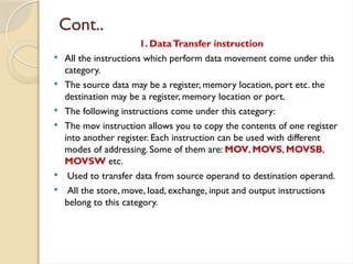
Cont..
1. DataTransfer instruction
All the instructions which perform data movement come under this
category.
The source data may be a register, memory location, port etc. the
destination may be a register, memory location or port.
The following instructions come under this category:
The mov instruction allows you to copy the contents of one register
into another register. Each instruction can be used with different
modes of addressing. Some of them are: MOV, MOVS, MOVSB,
MOVSW etc.
Used to transfer data from source operand to destination operand.
All the store, move, load, exchange, input and output instructions
belong to this category.
6.
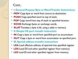
Cont..
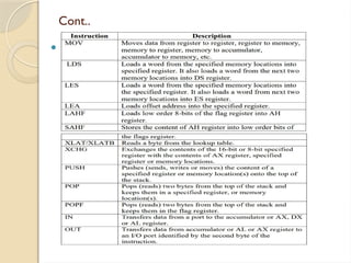
I. General-PurposeByte orWordTransfer Instructions:
MOV Copy byte or word from source to destination.
PUSH Copy specified word to top of stack.
POP Copy word from top of stack to specified location.
XCHG Exchange bytes or exchange words.
XLAT Translate a byte in AL using a table in memory.
II. Simple I/O port transfer instruction
IN Copy a byte or word from specified port to accumulator.
OUT Copy a byte or word from accumulator to specified port.
III. Special address transfer instructions
LEA Load effective address of operand into specified register.
LDS Load DS and other specified register from memory.
LES Load ES and other specified register from memory.
7.
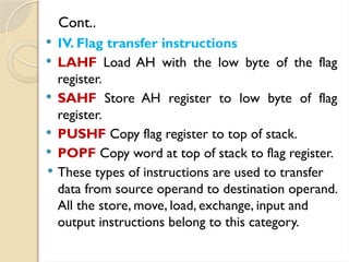
Cont..
IV. Flagtransfer instructions
LAHF Load AH with the low byte of the flag
register.
SAHF Store AH register to low byte of flag
register.
PUSHF Copy flag register to top of stack.
POPF Copy word at top of stack to flag register.
These types of instructions are used to transfer
data from source operand to destination operand.
All the store, move, load, exchange, input and
output instructions belong to this category.
8.
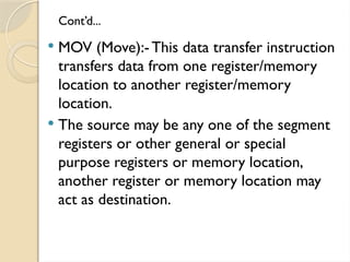
Cont’d...
MOV (Move):-This data transfer instruction
transfers data from one register/memory
location to another register/memory
location.
The source may be any one of the segment
registers or other general or special
purpose registers or memory location,
another register or memory location may
act as destination.
9.
Definition
The microprocessoris programmable device that takes in
numbers, performs on them arithmetic or logical
operations according to the program stored in memory and
then produces other numbers as a result.
Three basic characteristics differentiate microprocessors
are:
Instruction set: The set of instructions that the
microprocessor can execute.
Bandwidth: The number of bits processed in a single
instruction.
Clock speed: Given in megahertz (MHz), the clock speed
determines how many instructions per second the processor
can execute.
10.
Cont’d...
Internally, themicroprocessor is made up of
3 main units.
◦ The Arithmetic/Logic Unit (ALU)
◦ The Control Unit.
◦ An array of registers for holding data while it is
being manipulated.
11.
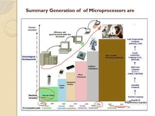
Evolution of Microprocessors
Fairchild Semiconductors (founded in 1957)
invented the first IC in 1959.
In 1968, Robert Noyce, Gordan Moore,
Andrew Grove resigned from Fairchild
Semiconductors.
They founded their own company Intel
(Integrated Electronics).
12.
Cont..
MP canbe classified based on following criteria
1. the width of data that can be processed
2. the instruction set
1. Classification of MP based on the data width,
based on data width MP can processing
instruction
◦ 4- BIT MICROPROCESSORS
◦ 8- BIT MICROPROCESSORS
◦ 16- BIT MICROPROCESSORS
◦ 32- BIT MICROPROCESSORS
◦ 64- BIT MICROPROCESSORS
13.
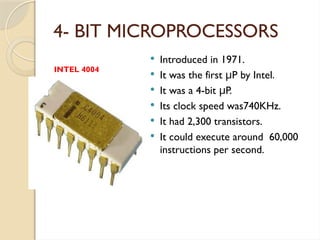
4- BIT MICROPROCESSORS
Introduced in 1971.
It was the first P by Intel.
μ
It was a 4-bit P.
μ
Its clock speed was740KHz.
It had 2,300 transistors.
It could execute around 60,000
instructions per second.
INTEL 4004
14.
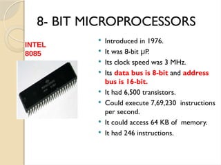
8- BIT MICROPROCESSORS
Introduced in 1976.
It was 8-bit P.
μ
Its clock speed was 3 MHz.
Its data bus is 8-bit and address
bus is 16-bit.
It had 6,500 transistors.
Could execute 7,69,230 instructions
per second.
It could access 64 KB of memory.
It had 246 instructions.
INTEL
8085
15.
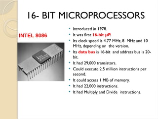
16- BIT MICROPROCESSORS
Introduced in 1978.
It was first 16-bit P.
μ
Its clock speed is 4.77 MHz, 8 MHz and 10
MHz, depending on the version.
Its data bus is 16-bit and address bus is 20-
bit.
It had 29,000 transistors.
Could execute 2.5 million instructions per
second.
It could access 1 MB of memory.
It had 22,000 instructions.
It had Multiply and Divide instructions.
INTEL 8086
16.
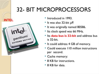
32- BIT MICROPROCESSORS
Introduced in 1993.
It was also 32-bit P.
μ
It was originally named 80586.
Its clock speed was 66 MHz.
Its data bus is 32-bit and address bus
is 32-bit.
It could address 4 GB of memory.
Could execute 110 million instructions
per second.
Cache memory:
8 KB for instructions.
8 KB for data.
INTEL
PENTIUM
17.
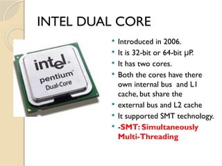
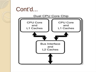
INTEL DUAL CORE
Introduced in 2006.
It is 32-bit or 64-bit P.
μ
It has two cores.
Both the cores have there
own internal bus and L1
cache, but share the
external bus and L2 cache
It supported SMT technology.
-SMT: Simultaneously
Multi-Threading
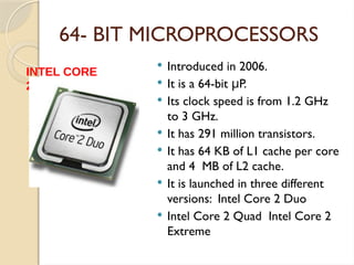
64- BIT MICROPROCESSORS
Introduced in 2006.
It is a 64-bit P.
μ
Its clock speed is from 1.2 GHz
to 3 GHz.
It has 291 million transistors.
It has 64 KB of L1 cache per core
and 4 MB of L2 cache.
It is launched in three different
versions: Intel Core 2 Duo
Intel Core 2 Quad Intel Core 2
Extreme
INTEL CORE
2
20.
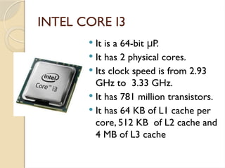
INTEL CORE I3
It is a 64-bit P.
μ
It has 2 physical cores.
Its clock speed is from 2.93
GHz to 3.33 GHz.
It has 781 million transistors.
It has 64 KB of L1 cache per
core, 512 KB of L2 cache and
4 MB of L3 cache
21.
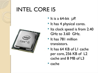
INTEL CORE I5
It is a 64-bit P.
μ
It has 4 physical cores.
Its clock speed is from 2.40
GHz to 3.60 GHz.
It has 781 million
transistors.
It has 64 KB of L1 cache
per core, 256 KB of L2
cache and 8 MB of L3
cache
22.
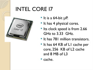
INTEL CORE I7
It is a 64-bit P.
μ
It has 4 physical cores.
Its clock speed is from 2.66
GHz to 3.33 GHz.
It has 781 million transistors.
It has 64 KB of L1 cache per
core, 256 KB of L2 cache
and 8 MB of L3
cache.
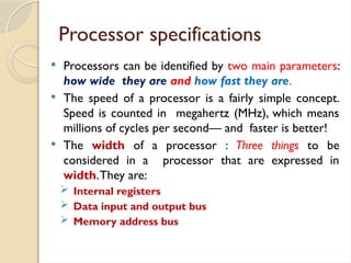
Processor specifications
Processorscan be identified by two main parameters:
how wide they are and how fast they are.
The speed of a processor is a fairly simple concept.
Speed is counted in megahertz (MHz), which means
millions of cycles per second— and faster is better!
The width of a processor : Three things to be
considered in a processor that are expressed in
width.They are:
Internal registers
Data input and output bus
Memory address bus
27.
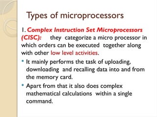
Types of microprocessors
1.Complex Instruction Set Microprocessors
(CISC): they categorize a micro processor in
which orders can be executed together along
with other low level activities.
It mainly performs the task of uploading,
downloading and recalling data into and from
the memory card.
Apart from that it also does complex
mathematical calculations within a single
command.
28.
Cont’d…
2. Reduced InstructionSet Computer (RISC): These kinds of
chips are made according to the function in which the
microprocessor can carry out small things within a particular
command.
In this way it completes more commands at a faster rate.
3. Superscalar Processors: This is a processor that copies the
hardware on the microprocessor for performing numerous tasks
at a time.They can be used for arithmetic and as multipliers.
They have several operational units and thus carry out more
than a one command by constantly transmitting various
instructions to the superfluous operational units inside the
processor.
29.
Cont’d…
4.The Application SpecificIntegrated Circuit:This processor is
also known as ASIC. They are used for specific purposes that
comprises of automotive emissions control or personal digital
assistants computer.
This kind of processor is made with proper specification but
apart from that it can also be made using the off the shelf
gears.
5. Digital Signal Multiprocessors:Also called as DSP’s, these are
used for encoding and decoding videos or to convert the digital
and video to analog and analog to digital.
They need a microprocessor that is excellent in mathematical
calculations.
The chips of this processor are employed in SONAR, RADAR,
home theaters audio gears, Mobile phones and TV set top
boxes.
cont.…
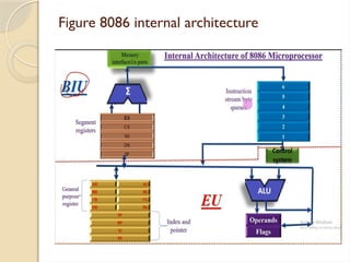
The BIU:-
◦ Sendsout addresses
◦ Fetches Instructions from memory
◦ Reads data from ports and memory
◦ Writes data to ports and memory.
The BIU handles all transfers of data and
addresses on the buses for the execution
unit.
36.
Cont…
The EU:-
◦Tells the BIU where to fetch instructions or data
from
◦ Decodes instructions.
◦ Executes instructions.
37.
The Execution Unit
It contains:-
◦ Control circuitry which directs internal
operations.
◦ A decoder which translates instructions fetched
from memory into a series of actions which the
EU carries out.
◦ A l6-bit arithmetic logic unit which can add,
subtract,AND, OR, XOR, increment, decrement,
complement, or shift binary numbers.
38.
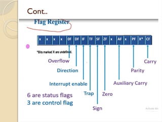
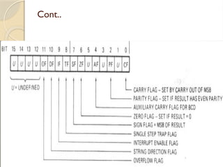
Flag Register
Aflag is a flip-flop which indicates some
condition produced by the execution of an
instruction or controls certain operations
of the EU.
A l6-bit flag register in the EU contains nine
active flags.
Six of the nine flags are used to indicate
some condition produced by an instruction.
39.
Cont…
The sixconditional flags in this group
are:-
◦ Carry Flag (CF)
◦ Parity Flag (PF)
◦ Auxiliary Flag (AF)
◦ Zero jag (ZF)
◦ Sign Flag (SF)
◦ Overflow Flag (OF).
40.
Cont…
The threeremaining flags in the flag register
are used to control certain operations of the
processor.
The six conditional flags are set or reset by
the EU on the basis of the results of some
arithmetic or logic operation.
41.
Cont…
The threecontrol flags are:-
◦ Trap Flag (TF), which is used for single
stepping through a program.
◦ Interrupt Flag (IF), which is used to allow or
prohibit the interruption of a program.
◦ Direction Flag (DF), which is used with
string instructions.
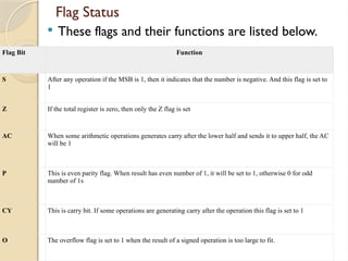
Flag Status
Theseflags and their functions are listed below.
Flag Bit Function
S After any operation if the MSB is 1, then it indicates that the number is negative. And this flag is set to
1
Z If the total register is zero, then only the Z flag is set
AC When some arithmetic operations generates carry after the lower half and sends it to upper half, the AC
will be 1
P This is even parity flag. When result has even number of 1, it will be set to 1, otherwise 0 for odd
number of 1s
CY This is carry bit. If some operations are generating carry after the operation this flag is set to 1
O The overflow flag is set to 1 when the result of a signed operation is too large to fit.
45.
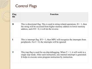
Control Flags
Flag
Bit
Function
D Thisis directional flag. This is used in string related operations. D = 1, then
the string will be accessed from higher memory address to lower memory
address, and if D = 0, it will do the reverse.
I This is interrupt flag. If I = 1, then MPU will recognize the interrupts from
peripherals. For I = 0, the interrupts will be ignored
T This trap flag is used for on-chip debugging. When T = 1, it will work in a
single step mode. After each instruction, one internal interrupt is generated.
It helps to execute some program instruction by instruction.
46.
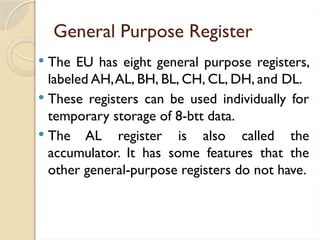
General Purpose Register
The EU has eight general purpose registers,
labeled AH,AL, BH, BL, CH, CL, DH, and DL.
These registers can be used individually for
temporary storage of 8-btt data.
The AL register is also called the
accumulator. It has some features that the
other general-purpose registers do not have.
47.
CONT. . .
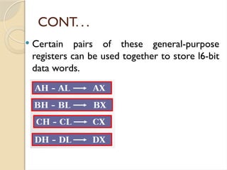
Certain pairs of these general-purpose
registers can be used together to store l6-bit
data words.
48.
Cont’d...
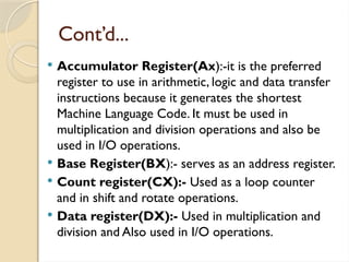
Accumulator Register(Ax):-itis the preferred
register to use in arithmetic, logic and data transfer
instructions because it generates the shortest
Machine Language Code. It must be used in
multiplication and division operations and also be
used in I/O operations.
Base Register(BX):- serves as an address register.
Count register(CX):- Used as a loop counter
and in shift and rotate operations.
Data register(DX):- Used in multiplication and
division and Also used in I/O operations.
49.
The Queue
TheBIU stores prefetched instruction bytes
in a first-infirst-out register set called a
queue.
When the EU is ready for its next instruction,
it simply reads the instruction byte (s) for the
instruction from the queue in the BIU.
Fetching the next instruction while the
current instruction executes is called
pipelining.