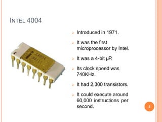
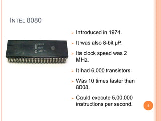
HISTORY OF
MICROPROCESSORS
1
CONTENTS
 Introduction
 4-Bit Microprocessors
 8-Bit Microprocessors
 16-Bit Microprocessors
 32-Bit Microprocessors
 64-Bit Microprocessors
2
INTRODUCTION
 Fairchild Semiconductors (founded in 1957)
invented the first IC in 1959.
 In 1968, Robert Noyce, Gordan Moore, Andrew
Grove resigned from Fairchild Semiconductors.
 They founded their own company Intel (Integrated
Electronics).
 Intel grown from 3 man start-up in 1968
3
4-BIT MICROPROCESSORS
4
INTEL 4004
 Introduced in 1971.
 It was the first
microprocessor by Intel.
 It was a 4-bit µP.
 Its clock speed was
740KHz.
 It had 2,300 transistors.
 It could execute around
60,000 instructions per
second. 5
INTEL 4040
 Introduced in 1974.
 It was also 4-bit µP.
6
8-BIT MICROPROCESSORS
7
INTEL 8008
 Introduced in 1972.
 It was first 8-bit µP.
 Its clock speed was 500
KHz.
 Could execute 50,000
instructions per second.
8
INTEL 8080
 Introduced in 1974.
 It was also 8-bit µP.
 Its clock speed was 2
MHz.
 It had 6,000 transistors.
 Was 10 times faster than
8008.
 Could execute 5,00,000
instructions per second. 9
INTEL 8085
 Introduced in 1976.
 It was also 8-bit µP.
 Its clock speed was 3 MHz.
 Its data bus is 8-bit and
address bus is 16-bit.
 It had 6,500 transistors.
 Could execute 7,69,230
instructions per second.
 It could access 64 KB of
memory.
 It had 246 instructions.
10
16-BIT MICROPROCESSORS
11
INTEL 8086
 Introduced in 1978.
 It was first 16-bit µP.
 Its clock speed is 4.77 MHz, 8
MHz and 10 MHz, depending on
the version.
 Its data bus is 16-bit and
address bus is 20-bit.
 It had 29,000 transistors.
 Could execute 2.5 million
instructions per second.
 It could access 1 MB of memory.
 It had 22,000 instructions.
 It had Multiply and Divide
instructions.
12
INTEL 8088
 Introduced in 1979.
 It was also 16-bit µP.
 It was created as a cheaper
version of Intel’s 8086.
 It was a 16-bit processor with
an 8-bit external bus.
13
INTEL 80186 & 80188
 Introduced in 1982.
 They were 16-bit µPs.
 Clock speed was 6 MHz.
14
INTEL 80286
 Introduced in 1982.
 It was 16-bit µP.
 Its clock speed was 8 MHz.
15
32-BIT MICROPROCESSORS
16
INTEL 80386
 Introduced in 1986.
 It was first 32-bit µP.
 Its data bus is 32-bit and
address bus is 32-bit.
 It could address 4 GB of
memory.
17
INTEL 80486
 Introduced in 1989.
 It was also 32-bit µP.
 It had 1.2 million transistors.
 Its clock speed varied from 16
MHz to 100 MHz depending
upon the various versions.
18
INTEL PENTIUM
 Introduced in 1993.
 It was also 32-bit µP.
 It was originally named 80586.
 Its clock speed was 66 MHz.
19
INTEL PENTIUM PRO
 Introduced in 1995.
 It was also 32-bit µP.
INTEL PENTIUM II
 Introduced in 1997.
 It was also 32-bit µP
.
21
INTEL PENTIUM II XEON
 Introduced in 1998.
 It was also 32-bit µP.
22
INTEL PENTIUM III
 Introduced in 1999.
 It was also 32-bit µP.
23
INTEL PENTIUM IV
 Introduced in 2000.
 It was also 32-bit µP
.
24
INTEL DUAL CORE
 Introduced in 2006.
 It is 32-bit or 64-bit µP.
 It has two cores.
 Both the cores have there
own internal bus and L1
cache, but share the
external bus and L2 cache
25
26
64-BIT MICROPROCESSORS
27
INTEL CORE 2
 Introduced in 2006.
 It is a 64-bit µP
.
28
INTEL CORE I7
 Introduced in 2008.
 It is a 64-bit µP.
29
INTEL CORE I5
 Introduced in 2009.
 It is a 64-bit µP.
30
INTEL CORE I3
 Introduced in 2010.
 It is a 64-bit µP.
31
The salient features of 8085
microprocessor.
8085 Microprocessor
The salient features of 8085 μp are :
1. It is a 8 bit microprocessor.
2. It has 16 bit address bus and hence can
address up to 216 = 65536 bytes (64KB)
memory locations through A0-A15.
3. The first 8 lines of address bus and 8 lines
of data bus are multiplexed AD0 – AD7.
4. Data bus is a group of 8 lines D0 – D7.
5. It supports 5 hardware interrupt and 8
software interrupt.
8085 Microprocessor
6. A 16 bit program counter (PC)
7. A 16 bit stack pointer (SP)
8. Six 8-bit general purpose register
arranged in pairs: BC,DE, HL.
9. It requires a signal +5V power supply
10.Maximum Clock Frequency is 3MHz
and Minimum Clock Frequency is
500kHz
Pin Diagram of 8085
X1 & X2
Pin 1 and Pin 2 (Input)
These are also called
Crystal Input Pins.
8085 can generate
clock signals
internally.
To generate clock
signals internally,
8085 requires external
inputs from X1 and X2.
RESET IN and RESET OUT
Pin 36 (Input) and Pin 3 (Output)
RESET IN:
◦ It is used to reset the
microprocessor.
◦ It is active low signal.
◦ When the signal on this
pin is low for at least 3
clocking cycles, it
forces the
microprocessor to reset
itself.
Pin 36 (Input) and Pin 3 (Output)
Resetting the
microprocessor means:
◦ Clearing the PC and IR.
◦ Disabling all interrupts
(except TRAP).
◦ Disabling the SOD pin.
◦ All the buses (data,
address, control) are tri-
stated.
◦ Gives HIGH output to
RESET OUT pin.
RESET IN and RESET OUT
Pin 36 (Input) and Pin 3 (Output)
 RESET OUT:
◦ It is used to reset the
peripheral devices and other
ICs on the circuit.
◦ It is an output signal.
◦ It is an active high signal.
◦ The output on this pin goes
high whenever RESET IN is
given low signal.
◦ The output remains high as
long as RESET IN is kept low.
SID and SOD
Pin 4 (Input) and Pin 5 (Output)
SID (Serial Input
Data):
o It takes 1 bit input from
serial port of 8085.
o Stores the bit at the 8th
position (MSB) of the
Accumulator.
o RIM (Read Interrupt
Mask) instruction is
used to transfer the bit.
SID and SOD
Pin 4 (Input) and Pin 5 (Output)
SOD (Serial Output
Data):
o It takes 1 bit from
Accumulator to serial port
of 8085.
o Takes the bit from the 8th
position (MSB) of the
Accumulator.
o SIM (Set Interrupt Mask)
instruction is used to
transfer the bit.
Interrupt Pins
 Interrupt:
• It means interrupting the normal execution of the
microprocessor.
• When microprocessor receives interrupt signal, it
discontinues whatever it was executing.
• It starts executing new program indicated by the interrupt
signal.
• Interrupt signals are generated by external peripheral
devices.
• After execution of the new program, microprocessor goes
back to the previous program.
Sequence of Steps Whenever There
is an Interrupt
Microprocessor completes execution of current
instruction of the program.
PC contents are stored in stack.
PC is loaded with address of the new program.
After executing the new program, the
microprocessor returns back to the previous
program.
It goes to the previous program by reading the
top value of stack.
Five Hardware Interrupts in 8085
TRAP
RST
7.5
RST
6.5
RST
5.5

history of microprocessor.pptx

  • 1.
  • 2.
    CONTENTS  Introduction  4-BitMicroprocessors  8-Bit Microprocessors  16-Bit Microprocessors  32-Bit Microprocessors  64-Bit Microprocessors 2
  • 3.
    INTRODUCTION  Fairchild Semiconductors(founded in 1957) invented the first IC in 1959.  In 1968, Robert Noyce, Gordan Moore, Andrew Grove resigned from Fairchild Semiconductors.  They founded their own company Intel (Integrated Electronics).  Intel grown from 3 man start-up in 1968 3
  • 4.
  • 5.
    INTEL 4004  Introducedin 1971.  It was the first microprocessor by Intel.  It was a 4-bit µP.  Its clock speed was 740KHz.  It had 2,300 transistors.  It could execute around 60,000 instructions per second. 5
  • 6.
    INTEL 4040  Introducedin 1974.  It was also 4-bit µP. 6
  • 7.
  • 8.
    INTEL 8008  Introducedin 1972.  It was first 8-bit µP.  Its clock speed was 500 KHz.  Could execute 50,000 instructions per second. 8
  • 9.
    INTEL 8080  Introducedin 1974.  It was also 8-bit µP.  Its clock speed was 2 MHz.  It had 6,000 transistors.  Was 10 times faster than 8008.  Could execute 5,00,000 instructions per second. 9
  • 10.
    INTEL 8085  Introducedin 1976.  It was also 8-bit µP.  Its clock speed was 3 MHz.  Its data bus is 8-bit and address bus is 16-bit.  It had 6,500 transistors.  Could execute 7,69,230 instructions per second.  It could access 64 KB of memory.  It had 246 instructions. 10
  • 11.
  • 12.
    INTEL 8086  Introducedin 1978.  It was first 16-bit µP.  Its clock speed is 4.77 MHz, 8 MHz and 10 MHz, depending on the version.  Its data bus is 16-bit and address bus is 20-bit.  It had 29,000 transistors.  Could execute 2.5 million instructions per second.  It could access 1 MB of memory.  It had 22,000 instructions.  It had Multiply and Divide instructions. 12
  • 13.
    INTEL 8088  Introducedin 1979.  It was also 16-bit µP.  It was created as a cheaper version of Intel’s 8086.  It was a 16-bit processor with an 8-bit external bus. 13
  • 14.
    INTEL 80186 &80188  Introduced in 1982.  They were 16-bit µPs.  Clock speed was 6 MHz. 14
  • 15.
    INTEL 80286  Introducedin 1982.  It was 16-bit µP.  Its clock speed was 8 MHz. 15
  • 16.
  • 17.
    INTEL 80386  Introducedin 1986.  It was first 32-bit µP.  Its data bus is 32-bit and address bus is 32-bit.  It could address 4 GB of memory. 17
  • 18.
    INTEL 80486  Introducedin 1989.  It was also 32-bit µP.  It had 1.2 million transistors.  Its clock speed varied from 16 MHz to 100 MHz depending upon the various versions. 18
  • 19.
    INTEL PENTIUM  Introducedin 1993.  It was also 32-bit µP.  It was originally named 80586.  Its clock speed was 66 MHz. 19
  • 20.
    INTEL PENTIUM PRO Introduced in 1995.  It was also 32-bit µP.
  • 21.
    INTEL PENTIUM II Introduced in 1997.  It was also 32-bit µP . 21
  • 22.
    INTEL PENTIUM IIXEON  Introduced in 1998.  It was also 32-bit µP. 22
  • 23.
    INTEL PENTIUM III Introduced in 1999.  It was also 32-bit µP. 23
  • 24.
    INTEL PENTIUM IV Introduced in 2000.  It was also 32-bit µP . 24
  • 25.
    INTEL DUAL CORE Introduced in 2006.  It is 32-bit or 64-bit µP.  It has two cores.  Both the cores have there own internal bus and L1 cache, but share the external bus and L2 cache 25
  • 26.
  • 27.
  • 28.
    INTEL CORE 2 Introduced in 2006.  It is a 64-bit µP . 28
  • 29.
    INTEL CORE I7 Introduced in 2008.  It is a 64-bit µP. 29
  • 30.
    INTEL CORE I5 Introduced in 2009.  It is a 64-bit µP. 30
  • 31.
    INTEL CORE I3 Introduced in 2010.  It is a 64-bit µP. 31
  • 32.
    The salient featuresof 8085 microprocessor.
  • 33.
    8085 Microprocessor The salientfeatures of 8085 μp are : 1. It is a 8 bit microprocessor. 2. It has 16 bit address bus and hence can address up to 216 = 65536 bytes (64KB) memory locations through A0-A15. 3. The first 8 lines of address bus and 8 lines of data bus are multiplexed AD0 – AD7. 4. Data bus is a group of 8 lines D0 – D7. 5. It supports 5 hardware interrupt and 8 software interrupt.
  • 34.
    8085 Microprocessor 6. A16 bit program counter (PC) 7. A 16 bit stack pointer (SP) 8. Six 8-bit general purpose register arranged in pairs: BC,DE, HL. 9. It requires a signal +5V power supply 10.Maximum Clock Frequency is 3MHz and Minimum Clock Frequency is 500kHz
  • 35.
  • 36.
    X1 & X2 Pin1 and Pin 2 (Input) These are also called Crystal Input Pins. 8085 can generate clock signals internally. To generate clock signals internally, 8085 requires external inputs from X1 and X2.
  • 37.
    RESET IN andRESET OUT Pin 36 (Input) and Pin 3 (Output) RESET IN: ◦ It is used to reset the microprocessor. ◦ It is active low signal. ◦ When the signal on this pin is low for at least 3 clocking cycles, it forces the microprocessor to reset itself.
  • 38.
    Pin 36 (Input)and Pin 3 (Output) Resetting the microprocessor means: ◦ Clearing the PC and IR. ◦ Disabling all interrupts (except TRAP). ◦ Disabling the SOD pin. ◦ All the buses (data, address, control) are tri- stated. ◦ Gives HIGH output to RESET OUT pin. RESET IN and RESET OUT
  • 39.
    RESET IN andRESET OUT Pin 36 (Input) and Pin 3 (Output)  RESET OUT: ◦ It is used to reset the peripheral devices and other ICs on the circuit. ◦ It is an output signal. ◦ It is an active high signal. ◦ The output on this pin goes high whenever RESET IN is given low signal. ◦ The output remains high as long as RESET IN is kept low.
  • 40.
    SID and SOD Pin4 (Input) and Pin 5 (Output) SID (Serial Input Data): o It takes 1 bit input from serial port of 8085. o Stores the bit at the 8th position (MSB) of the Accumulator. o RIM (Read Interrupt Mask) instruction is used to transfer the bit.
  • 41.
    SID and SOD Pin4 (Input) and Pin 5 (Output) SOD (Serial Output Data): o It takes 1 bit from Accumulator to serial port of 8085. o Takes the bit from the 8th position (MSB) of the Accumulator. o SIM (Set Interrupt Mask) instruction is used to transfer the bit.
  • 42.
    Interrupt Pins  Interrupt: •It means interrupting the normal execution of the microprocessor. • When microprocessor receives interrupt signal, it discontinues whatever it was executing. • It starts executing new program indicated by the interrupt signal. • Interrupt signals are generated by external peripheral devices. • After execution of the new program, microprocessor goes back to the previous program.
  • 43.
    Sequence of StepsWhenever There is an Interrupt Microprocessor completes execution of current instruction of the program. PC contents are stored in stack. PC is loaded with address of the new program. After executing the new program, the microprocessor returns back to the previous program. It goes to the previous program by reading the top value of stack.
  • 44.
    Five Hardware Interruptsin 8085 TRAP RST 7.5 RST 6.5 RST 5.5