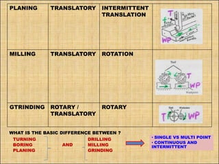
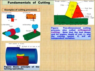
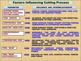
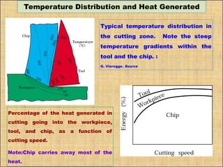
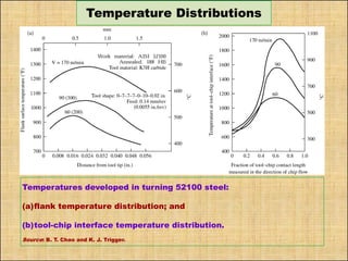
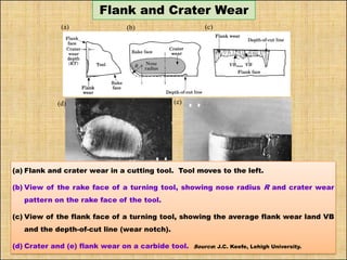
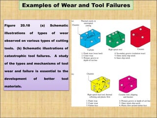
SlideShare a Scribd company logo
Email: vkjain@iitk.ac.in
Fundamentals of Cutting
ORGANIZATION
ACKNOWLEDGEMENT: A GOOD NO. OF PHOTOGRAPHS ARE FROM THE BOOK BY KALPAKJIAN
NATURE OF RELATIVE MOTION BETWEEN THE TOOL AND WORKPIECE
FUNDAMENTALS OF CUTTING
FACTORS INFLUENCING CUTTING PROCESS
TYPES OF CHIPS
CHIP BREAKERS
CUTTING TOOL
TYPES OF CUTTING
TEMPERATURE DISTRIBUTION
TOOL WEAR
MECHANICS OF CHIP FORMATION
INEFFICIENT BUT MOST IMPORTANT MANUFACTURING
PROCESS
MACHIING
CONDITIONS
M/C TOOL PRODUCT
WORK MATERAIL
CUTTING TOOL
Metal Cutting Plastic Deformation/Flow Process
Orthogonal Cutting
Oblique Cutting
Classification of Cutting
MATERIAL REMOVAL PROCESSES
MRPs
Traditional Advanced
Cutting Finishing
Circular
Shape
Other/Prismatic
Shape
Bonded
Abrasive
Loose
Abrasive
• Turning
• Drilling
• Boring
• Milling
• Planning
• Shaping
• Gear Cutting
• Broaching
• Grinding
• Honing
• Coated
Abrasive
• Lapping
• Polishing
Metal Cutting: Relative Motion between workpiece & cutting edge of tool
Cutting Tools: 1. Single Point tool
2. Multiple Point tool
NATURE OF RELATIVE MOTION BETWEEN
THE TOOL AND WORKPIECE
OPERATION MOTION OF
JOB
MOTION OF
CUTTING
TOOL
FIGURE OF
OPEARTION
TURNING ROTARY TRANSLATORY
(FORWARD)
BORING ROTATION TRANSLATION
(FORWARD)
DRILLING FIXED (NO
MOTION)
ROTATION AS
WELL AS
TRANSLATOR
Y FEED
PLANING TRANSLATORY INTERMITTENT
TRANSLATION
MILLING TRANSLATORY ROTATION
GTRINDING ROTARY /
TRANSLATORY
ROTARY
WHAT IS THE BASIC DIFFERENCE BETWEEN ?
TURNING
BORING
PLANING
DRILLING
MILLING
GRINDING
• SINGLE VS MULTI POINT
• CONTINUOUS AND
INTERMITTENT
AND
Fundamentals of Cutting
Examples of cutting processes.
Figure: Basic principle of the
turning operations.
Figure: Two-dimensional cutting
process, also called orthogonal
cutting. Note that the tool shape
and its angles, depth of cut, to, and
the cutting speed, V, are all
independent variables.
Types of Cutting
o Orthogonal Cutting (2-D Cutting):
Cutting edge is (1) straight, (2)parallel to the original plane surface on the
work piece and (3)perpendicular to the direction of cutting. For example:
Operations: Lathe cut-off operation, Straight milling, etc.
o Oblique Cutting (3-D Cutting):
Cutting edge of the tool is inclined to the line normal to the cutting
direction. In actual machining, Turning, Milling etc. / cutting operations are
oblique cutting(3-D)
ORTHOGONAL CUTTING
OBLIQUE CUTTING
Factors Influencing Cutting Process
PARAMETER INFLUENCE AND INTERRELATIONSHIP
CUTTING SPEED,
DEPTH OF CUT, FEED,
CUTTING FLUIDS
FORCES, POWER, TEMPERATURE RISE, TOOL LIFE,
TYPE OF CHIP, SURFACE FINISH.
TOOL ANGLES AS ABOVE, INFLUENCE ON CHIP FLOW DIRECTION,
RESISTANCE TO TOOL CHIPPING.
CONTINUOUS CHIP GOOD SURFACE FINISH; STEADY CUTTING FORCES;
UNDESIRABLE IN AUTOMATED MACHINERY.
BUILT-UP EDGE CHIP POOR SURFACE FINISH, THIN STABLE EDGE CAN
PROTECT TOOL SURFACES.
DISCONTINUOUS
CHIP
DESIRABLE FOR EASE OF CHIP DISPOSAL;
FLUCTUATING CUTTING FORCES; CAN AFFECT
SURFACE FINISH AND CAUSE VIBRATION AND
CHATTER.
TEMPERATURE RISE INFLUENCES TOOL LIFE, PARTICULARLY CRATER
WEAR, AND DIMENSIONAL ACCURACY OF
WORKPIECE; MAY CAUSE THERMAL DAMAGE TO
WORKPIECE SURFACE.
TOOL WEAR INFLUENCES SURFACE FINISH, DIMENSIONAL
ACCURACY, TEMPERATURE RISE, FORCES AND
POWER.
TOOL WEAR
MACHINABILITY
RELATED TO TOOL LIFE, SURFACE FINISH, FORCES
AND POWER
Mechanics of Chip Formation
(a) Basic mechanism of chip formation in metal cutting. (b)
Velocity diagram in the cutting zone.
V=> Cutting velocity, Vs= Shear velocity, Vc=Chip velocity
Φ= Shear angle, α=Rake angle
MECHANICS OF CHIP FORMATION
 Plastic deformation along shear plane
(Merchant)
 The fig. where the work piece remains
stationary and the tool advances in to the work
piece towards left.
 Thus the metal gets compressed very severely,
causing shear stress.
 This stress is maximum along the plane is
called shear plane.
 If the material of the workpiece is ductile, the
material flows plastically along the shear plane,
forming chip, which flows upwards along the
face of the tool.
 The tool will cut or shear off the metal, provided
by;
•The tool is harder than the work metal
•The tool is properly shaped so that its
edge can be effective in cutting the
metal.
•Provided there is movement of tool
relative to the material or vice versa, so
as to make cutting action possible.
Fig: Shear Plane
Primary shear
zone (PSDZ)
Secondary shear
deformation zone
(SSDZ)
Fig: Shear deformation
zones
Fig: Shaping
operation
Fig: Shear deformation
zones
Types of Chips
 Continues Chips
 Discontinues Chips
 Continuous Chips
with Built up Edge (BUE)
Conditions for Continuous
Chips:
• Sharp cutting edges
• Low feed rate (f)
• Large rake angle ()
• Ductile work material
• High cutting speed (v=)
• Low friction at Chip-Tool interface
CHIP FORMATION
Fig; Schematic of chip
formation
Fig; Schematic of different types of chip
Types of Chips
(a) Continuous chip
with narrow,
straight primary
shear zone;
(b) Secondary shear
zone at the chip-
tool interface;
(c) Continuous chip
with built-up edge
(d) Continuous chip
with large primary
shear zone
(e) Segmented or
nonhomogeneous
chip and
(f) Discontinuous
chip.
(f)
(b)
(a) (c)
(d) (e)
Source: After M. C. Shaw, P. K. Wright, and S. Kalpakjian.
Built-Up Edge Chips
(b)
(c)
(a)
(a) Hardness distribution in the cutting zone for 3115 steel. Note that some
regions in the built-up edge are as much as three times harder than the bulk
metal.
(b) (b) Surface finish in turning 5130 steel with a built-up edge. (c) surface finish
on 1018 steel in face milling. Magnifications: 15X. Source: Courtesy of
Metcut Research Associates, Inc.
TURNING LAY
MILLING LAY
Continuous chip Results in:
• Good surface finish
• High tool life
• Low power consumptions
Discontinuous Chip:
Chip in the form of discontinuous segments:
 Easy disposal
 Good surface finish
Conditions for discontinuous chips:
• Brittle Material
• Low cutting speed
• Small rake angle
Built up Edge:
Conditions for discontinuous chips:
High friction between Tool & chip
Ductile material
Particles of chip adhere to the rake face of the tool near cutting edge
Chip- Breaking
• The chip breaker break the produced chips into small pieces.
• The work hardening of the chip makes the work of the chip breakers
easy.
• When a strict chip control is desired, some sort of chip breaker has to be
employed.
• The following types of chip breakers are commonly used:
a) Groove type
b) Step type
c) Secondary Rake type
d) Clamp type
Fig: Schematics of different types of chip barkers
Chip Breakers
(a) Schematic illustration of the action of a chip breaker. Note that the chip
breaker decreases the radius of curvature of the chip. (b) Chip breaker
clamped on the rake face of a cutting tool. (c) Grooves in cutting tools
acting as chip breakers.
Examples of Chips Produced in Turning
Various chips produced in turning: (a) tightly curled chip; (b) chip hits
workpiece and breaks; (c) continuous chip moving away from workpiece;
and (d) chip hits tool shank and breaks off. Source: G. Boothroyd, Fundamentals of Metal
Machining and Machine Tools. Copyright © 1975; McGraw-Hill Publishing Company.
Tool Nomenclature/Angles
(a)
(c)
(b)
Fig: Turning Operations
Tool Nomenclature/Angles
Fig: Terms used in metal cutting (a) Positive rake; (b) Negative
rake
(a)
(b)
Right-Hand Cutting Tool
Figure 20.10 (a) Schematic illustration of a right-hand cutting tool.
Although these tools have traditionally been produced from solid
tool-steel bars, they have been largely replaced by carbide or other
inserts of various shapes and sizes, as shown in (b). The various
angles on these tools and their effects on machining are described in
Section 22.3.1.
Types of Cutting
o Orthogonal Cutting (2-D Cutting):
Cutting edge is straight, parallel to the original plane surface at
the work piece and perpendicular to the direction of cutting.
E.g. Operations:
• Lathe cut-off tools
• Straight milling cutters etc.
o Oblique Cutting:
Cutting edge of the tool is inclined to the line normal to the
cutting direction. In actual machining, Turning, Milling etc/ cutting
operations are oblique cutting(3-D
Forces in Two-Dimensional Cutting
/ Orthogonal Cutting
Forces acting on a cutting tool in two-dimensional cutting.
Note that the resultant force, R, must be collinear to balance the forces.
Cutting With an Oblique Tool
(a)Schematic illustration of cutting with an oblique tool.
(b)Top view showing the inclination angle, i.
(c)Types of chips produced with different inclination.
Approximate Energy Requirements in Cutting Operations
Approximate Energy Requirements in Cutting Operations (at
drive motor, corrected for 80% efficiency; multiply
by 1.25 for dull tools).
Specific energy
Material W-s/mm
3
hp-min/in.
3
Aluminum alloys
Cast irons
Copper alloys
High-temperature alloys
Nickel alloys
Refractory alloys
Stainless steels
Steels
Titanium alloys
0.4–1.1
1.6–5.5
1.4–3.3
3.3–8.5
0.4–0.6
4.9–6.8
3.8–9.6
3.0–5.2
2.7–9.3
3.0–4.1
0.15–0.4
0.6–2.0
0.5–1.2
1.2–3.1
0.15–0.2
1.8–2.5
1.1–3.5
1.1–1.9
1.0–3.4
1.1–1.5
Temperature Distribution and Heat Generated
Typical temperature distribution in
the cutting zone. Note the steep
temperature gradients within the
tool and the chip. :
G. Vieregge. Source
Percentage of the heat generated in
cutting going into the workpiece,
tool, and chip, as a function of
cutting speed.
Note:Chip carries away most of the
heat.
Temperature Distributions
Temperatures developed in turning 52100 steel:
(a)flank temperature distribution; and
(b)tool-chip interface temperature distribution.
Source: B. T. Chao and K. J. Trigger.
Flank and Crater Wear
(e)
(d)
(a) (b) (c)
(a) Flank and crater wear in a cutting tool. Tool moves to the left.
(b) View of the rake face of a turning tool, showing nose radius R and crater wear
pattern on the rake face of the tool.
(c) View of the flank face of a turning tool, showing the average flank wear land VB
and the depth-of-cut line (wear notch).
(d) Crater and (e) flank wear on a carbide tool. Source: J.C. Keefe, Lehigh University.
Tool Wear
Allowable Average Wear Land (VB) for Cutting
Tools in Various Operations
Allowable wear land (mm)
Operation High-speed Steels Carbides
Turning
Face milling
End milling
Drilling
Reaming
1.5
1.5
0.3
0.4
0.15
0.4
0.4
0.3
0.4
0.15
Note: 1 mm = 0.040 in.
Surfaces Produced by Cutting
Figure 20.21 Surfaces produced on steel by cutting, as observed
with a scanning electron microscope: (a) turned surface and (b)
surface produced by shaping. Source: J. T. Black and S.
Ramalingam.
(b)
(a)
Dull Tool in Orthogonal Cutting and Feed Marks
Schematic illustration of a dull tool in
orthogonal cutting (exaggerated). Note that
at small depths of cut, the positive rake angle
can effectively become negative, and the tool
may simply ride over and burnish the
workpiece surface.
Schematic illustration of feed
marks in turning (highly
exaggerated).
( )
( )
1
1
1
1 1 1 1
1 1
3
500
0.15 /
0.3
, .
500 2
25
60
1308.9 / sec
1308.9 0.15 0.3
58.905 / sec
c
c
c
v
v c
v
v
N RPM
f mm rev
d mm
CuttingSpeed V R
V
V mm
MRR D N f d
MRR V f d
MRR
MRR mm
ω
π
π
=
=
=
=
×
 
= ×
 
 
=
= × × ⋅
= ⋅
= × ×
=
D1
L
Depth of cut
Feed
N1
W/P
Tool
Turning operation
Problem-1:
A turning operation has to be performed on an aluminum rod of diameter50 mm and
length 300mm. The Spindle speed of lathe is given to be 500 RPM. The feed and depth of
cut are 0.15mm/rev and 0.3 mm respectively. Draw a neat sketch of the turning
operation described above. Find out the cutting speed in mm/s and the volumetric
material removal rate (MRRv).
Solution:
Problem-2
An aluminum block of length 50 mm and width 70 mm is being milled using a slab milling
cutter with 50 mm diameter. The feed of the table is 15 mm/min. The milling cutter
rotates at 60 RPM in clockwise direction and width of cut is equal to the width of the
workpiece. Draw a neat sketch of the milling operation describing above conditions. The
thickness of the workpiece is 20 mm. If depth of cut of 2 mm is used then find out
cutting speed and volumetric material removal rate (MRRv).
Milling operation
N2
W
L
D
2
W
Feed
Milling cutter
W/P
t
2
2
2
2
2 2
3
, 50
, 70
, 2
, 15 / min
, / min
1000
50 60
25
1000
9.424 / min
15
70 2
60
35 / sec
c
c
c
v
v
v
Milling Cutter Diameter D mm
Width of cut WOC mm
Depth of cut d mm
feed f mm
DN
Cutting Speed V m
V
V m
MRR WOC f d
MRR
MRR mm
π
π
=
=
=
=
=
× ×
 
= ×
 
 
=
= ⋅ ⋅
= × ×
=
Solution:
Problem-3
Following the milling operation, a through hole is to be drilled on the same workpiece.
Find out the cutting speed and volumetric material removal rate if the drill of diameter 10
mm is being rotated at same RPM as in case of milling cutter with feed rate as 0.5
mm/rev.
W/P
Feed
D
3
N3
Drilling operation
Drill bit
t
3
3
3
3 3
2
3
3 3
2
3 3
, 10
60
, 0.5 /
, / min
1000
60 10
/ min
1000
1.884 / min 31.4 / sec
4
10
0.5 60
4
2356.19 / min 39.27 / sec
c
c
c
v
v
v
Diameter of Drill D mm
N RPM
feed f mm rev
N D
Cutting Speed V m
V m
V m mm
D
MRR f N
MRR
MRR mm mm
π
π
π
π
=
=
=
=
× ×
 
=  
 
= =
×
= × ×
×
= × ×
= =
Solution:
36
THANK YOU
Crater Wear
Figure 20.19 Relationship between crater-
wear rate and average tool-chip interface
temperature: (a) High-speed steel; (b) C-1
carbide; and (c) C-5 carbide. Note how
rapidly crater-wear rate increases as the
temperature increases. Source: B. T. Chao
and K. J. Trigger.
Cutting tool (right) and chip (left) interface in
cutting plain-carbon steel. The discoloration of the
tool indicates the presence of high temperatures.
Source: P. K. Wright.
Examples of Wear and Tool Failures
Figure 20.18 (a) Schematic
illustrations of types of wear
observed on various types of cutting
tools. (b) Schematic illustrations of
catastrophic tool failures. A study
of the types and mechanisms of tool
wear and failure is essential to the
development of better tool
materials.
Range of n Values for Eq. (20.20) for Various
Tool Materials
High-speed steels
Cast alloys
Carbides
Ceramics
0.08–0.2
0.1–0.15
0.2–0.5
0.5–0.7
Tool Life
Tool-life curves for a
variety of cutting-tool
materials. The negative
inverse of the slope of
these curves is the
exponent n in the Taylor
tool-life equations and C
is the cutting speed at T
= 1 min.

More Related Content

Similar to Metalcutting.pdf

Sheet metworking 1
Sheet metworking 1Sheet metworking 1
Sheet metworking 1sundar sivam
 
Mechanics of Chip Formation - Unit of MFT
Mechanics of Chip Formation - Unit of MFTMechanics of Chip Formation - Unit of MFT
Mechanics of Chip Formation - Unit of MFT
hodmech61
 
MP_ Fundmentals of Machining.pdf
MP_ Fundmentals of Machining.pdfMP_ Fundmentals of Machining.pdf
MP_ Fundmentals of Machining.pdf
RuturajTanwade
 
azad alam alig
 azad alam alig azad alam alig
azad alam alig
azadalig
 
THEORY OF METAL MACHINING.pptx
THEORY OF METAL MACHINING.pptxTHEORY OF METAL MACHINING.pptx
THEORY OF METAL MACHINING.pptx
Dr. J S Sri Kantamurthy
 
Unit test 1 - mt-ii -answer key
Unit test 1 - mt-ii -answer keyUnit test 1 - mt-ii -answer key
Unit test 1 - mt-ii -answer key
mohanraj r
 
Machining.pptx
Machining.pptxMachining.pptx
Machining.pptx
FebrianJha
 
Machining .pdf
Machining .pdfMachining .pdf
Machining .pdf
FebrianJha
 
Sheet metal working
Sheet metal workingSheet metal working
Sheet metal working
raxit varmora
 
manufacturing process and their science
manufacturing process and their sciencemanufacturing process and their science
manufacturing process and their science
JOSE BABU
 
Production technology Metal Cutting introduction
Production technology Metal Cutting introductionProduction technology Metal Cutting introduction
Production technology Metal Cutting introduction
Ahmedabad Institute Of Technology
 
4_cutting.ppt
4_cutting.ppt4_cutting.ppt
4_cutting.ppt
KUMARR80
 
4_cutting.ppt
4_cutting.ppt4_cutting.ppt
4_cutting.ppt
KANWARGILL16
 
2. Cutting Tools.pdf
2. Cutting Tools.pdf2. Cutting Tools.pdf
2. Cutting Tools.pdf
harinadh018
 
ACE305: Aircraft Components Design and Manufacture
ACE305: Aircraft Components Design and ManufactureACE305: Aircraft Components Design and Manufacture
ACE305: Aircraft Components Design and Manufacture
Dr Mohamed Elfarran
 
Machine tools
Machine toolsMachine tools
Machine tools
Anantha Krishnan
 
Metal cutting basics-min.docx
Metal cutting basics-min.docxMetal cutting basics-min.docx
Metal cutting basics-min.docx
ssuser72b8e8
 
Manufacturing Processes(Sheet Metal Forming.ppt)
Manufacturing Processes(Sheet Metal Forming.ppt)Manufacturing Processes(Sheet Metal Forming.ppt)
Manufacturing Processes(Sheet Metal Forming.ppt)
sadanand50
 

Similar to Metalcutting.pdf (20)

Sheet metworking 1
Sheet metworking 1Sheet metworking 1
Sheet metworking 1
 
Mechanics of Chip Formation - Unit of MFT
Mechanics of Chip Formation - Unit of MFTMechanics of Chip Formation - Unit of MFT
Mechanics of Chip Formation - Unit of MFT
 
MP_ Fundmentals of Machining.pdf
MP_ Fundmentals of Machining.pdfMP_ Fundmentals of Machining.pdf
MP_ Fundmentals of Machining.pdf
 
azad alam alig
 azad alam alig azad alam alig
azad alam alig
 
THEORY OF METAL MACHINING.pptx
THEORY OF METAL MACHINING.pptxTHEORY OF METAL MACHINING.pptx
THEORY OF METAL MACHINING.pptx
 
Unit test 1 - mt-ii -answer key
Unit test 1 - mt-ii -answer keyUnit test 1 - mt-ii -answer key
Unit test 1 - mt-ii -answer key
 
Machining.pptx
Machining.pptxMachining.pptx
Machining.pptx
 
Machining .pdf
Machining .pdfMachining .pdf
Machining .pdf
 
Sheet metal working
Sheet metal workingSheet metal working
Sheet metal working
 
manufacturing process and their science
manufacturing process and their sciencemanufacturing process and their science
manufacturing process and their science
 
Production technology Metal Cutting introduction
Production technology Metal Cutting introductionProduction technology Metal Cutting introduction
Production technology Metal Cutting introduction
 
4_cutting.ppt
4_cutting.ppt4_cutting.ppt
4_cutting.ppt
 
4_cutting.ppt
4_cutting.ppt4_cutting.ppt
4_cutting.ppt
 
2. Cutting Tools.pdf
2. Cutting Tools.pdf2. Cutting Tools.pdf
2. Cutting Tools.pdf
 
ACE305: Aircraft Components Design and Manufacture
ACE305: Aircraft Components Design and ManufactureACE305: Aircraft Components Design and Manufacture
ACE305: Aircraft Components Design and Manufacture
 
Machine tools
Machine toolsMachine tools
Machine tools
 
Metal cutting basics-min.docx
Metal cutting basics-min.docxMetal cutting basics-min.docx
Metal cutting basics-min.docx
 
Week 1 mill 1
Week 1   mill 1Week 1   mill 1
Week 1 mill 1
 
Mtii
MtiiMtii
Mtii
 
Manufacturing Processes(Sheet Metal Forming.ppt)
Manufacturing Processes(Sheet Metal Forming.ppt)Manufacturing Processes(Sheet Metal Forming.ppt)
Manufacturing Processes(Sheet Metal Forming.ppt)
 

More from TANVEERSINGHSOLANKI

phpapp.pptx
phpapp.pptxphpapp.pptx
phpapp.pptx
TANVEERSINGHSOLANKI
 
machinability index.pptx
machinability index.pptxmachinability index.pptx
machinability index.pptx
TANVEERSINGHSOLANKI
 
CLIENTS ABOUT CLIENTS HOW TO DEAL WITH THEM.pptx
CLIENTS ABOUT CLIENTS HOW TO DEAL WITH THEM.pptxCLIENTS ABOUT CLIENTS HOW TO DEAL WITH THEM.pptx
CLIENTS ABOUT CLIENTS HOW TO DEAL WITH THEM.pptx
TANVEERSINGHSOLANKI
 
centrifugal compressors.pptx
centrifugal compressors.pptxcentrifugal compressors.pptx
centrifugal compressors.pptx
TANVEERSINGHSOLANKI
 
Tomorrow SEMINAR OR.pptx
Tomorrow SEMINAR OR.pptxTomorrow SEMINAR OR.pptx
Tomorrow SEMINAR OR.pptx
TANVEERSINGHSOLANKI
 
Seminar(PRESENTATION).pptx
Seminar(PRESENTATION).pptxSeminar(PRESENTATION).pptx
Seminar(PRESENTATION).pptx
TANVEERSINGHSOLANKI
 
Metal cutting operations and terminology.pptx
Metal cutting operations and terminology.pptxMetal cutting operations and terminology.pptx
Metal cutting operations and terminology.pptx
TANVEERSINGHSOLANKI
 
Simulation.ppt
Simulation.pptSimulation.ppt
Simulation.ppt
TANVEERSINGHSOLANKI
 
Operations Research Digital Material.pdf
Operations Research Digital Material.pdfOperations Research Digital Material.pdf
Operations Research Digital Material.pdf
TANVEERSINGHSOLANKI
 

More from TANVEERSINGHSOLANKI (12)

today2.pptx
 today2.pptx today2.pptx
today2.pptx
 
phpapp.pptx
phpapp.pptxphpapp.pptx
phpapp.pptx
 
Metal270.pptx
Metal270.pptxMetal270.pptx
Metal270.pptx
 
machinability index.pptx
machinability index.pptxmachinability index.pptx
machinability index.pptx
 
lubrication.ppt
lubrication.pptlubrication.ppt
lubrication.ppt
 
CLIENTS ABOUT CLIENTS HOW TO DEAL WITH THEM.pptx
CLIENTS ABOUT CLIENTS HOW TO DEAL WITH THEM.pptxCLIENTS ABOUT CLIENTS HOW TO DEAL WITH THEM.pptx
CLIENTS ABOUT CLIENTS HOW TO DEAL WITH THEM.pptx
 
centrifugal compressors.pptx
centrifugal compressors.pptxcentrifugal compressors.pptx
centrifugal compressors.pptx
 
Tomorrow SEMINAR OR.pptx
Tomorrow SEMINAR OR.pptxTomorrow SEMINAR OR.pptx
Tomorrow SEMINAR OR.pptx
 
Seminar(PRESENTATION).pptx
Seminar(PRESENTATION).pptxSeminar(PRESENTATION).pptx
Seminar(PRESENTATION).pptx
 
Metal cutting operations and terminology.pptx
Metal cutting operations and terminology.pptxMetal cutting operations and terminology.pptx
Metal cutting operations and terminology.pptx
 
Simulation.ppt
Simulation.pptSimulation.ppt
Simulation.ppt
 
Operations Research Digital Material.pdf
Operations Research Digital Material.pdfOperations Research Digital Material.pdf
Operations Research Digital Material.pdf
 

Recently uploaded

Francesca Gottschalk - How can education support child empowerment.pptx
Francesca Gottschalk - How can education support child empowerment.pptxFrancesca Gottschalk - How can education support child empowerment.pptx
Francesca Gottschalk - How can education support child empowerment.pptx
EduSkills OECD
 
Honest Reviews of Tim Han LMA Course Program.pptx
Honest Reviews of Tim Han LMA Course Program.pptxHonest Reviews of Tim Han LMA Course Program.pptx
Honest Reviews of Tim Han LMA Course Program.pptx
timhan337
 
CACJapan - GROUP Presentation 1- Wk 4.pdf
CACJapan - GROUP Presentation 1- Wk 4.pdfCACJapan - GROUP Presentation 1- Wk 4.pdf
CACJapan - GROUP Presentation 1- Wk 4.pdf
camakaiclarkmusic
 
Phrasal Verbs.XXXXXXXXXXXXXXXXXXXXXXXXXX
Phrasal Verbs.XXXXXXXXXXXXXXXXXXXXXXXXXXPhrasal Verbs.XXXXXXXXXXXXXXXXXXXXXXXXXX
Phrasal Verbs.XXXXXXXXXXXXXXXXXXXXXXXXXX
MIRIAMSALINAS13
 
Biological Screening of Herbal Drugs in detailed.
Biological Screening of Herbal Drugs in detailed.Biological Screening of Herbal Drugs in detailed.
Biological Screening of Herbal Drugs in detailed.
Ashokrao Mane college of Pharmacy Peth-Vadgaon
 
Palestine last event orientationfvgnh .pptx
Palestine last event orientationfvgnh .pptxPalestine last event orientationfvgnh .pptx
Palestine last event orientationfvgnh .pptx
RaedMohamed3
 
Acetabularia Information For Class 9 .docx
Acetabularia Information For Class 9  .docxAcetabularia Information For Class 9  .docx
Acetabularia Information For Class 9 .docx
vaibhavrinwa19
 
TESDA TM1 REVIEWER FOR NATIONAL ASSESSMENT WRITTEN AND ORAL QUESTIONS WITH A...
TESDA TM1 REVIEWER  FOR NATIONAL ASSESSMENT WRITTEN AND ORAL QUESTIONS WITH A...TESDA TM1 REVIEWER  FOR NATIONAL ASSESSMENT WRITTEN AND ORAL QUESTIONS WITH A...
TESDA TM1 REVIEWER FOR NATIONAL ASSESSMENT WRITTEN AND ORAL QUESTIONS WITH A...
EugeneSaldivar
 
Home assignment II on Spectroscopy 2024 Answers.pdf
Home assignment II on Spectroscopy 2024 Answers.pdfHome assignment II on Spectroscopy 2024 Answers.pdf
Home assignment II on Spectroscopy 2024 Answers.pdf
Tamralipta Mahavidyalaya
 
The Challenger.pdf DNHS Official Publication
The Challenger.pdf DNHS Official PublicationThe Challenger.pdf DNHS Official Publication
The Challenger.pdf DNHS Official Publication
Delapenabediema
 
Model Attribute Check Company Auto Property
Model Attribute  Check Company Auto PropertyModel Attribute  Check Company Auto Property
Model Attribute Check Company Auto Property
Celine George
 
How libraries can support authors with open access requirements for UKRI fund...
How libraries can support authors with open access requirements for UKRI fund...How libraries can support authors with open access requirements for UKRI fund...
How libraries can support authors with open access requirements for UKRI fund...
Jisc
 
678020731-Sumas-y-Restas-Para-Colorear.pdf
678020731-Sumas-y-Restas-Para-Colorear.pdf678020731-Sumas-y-Restas-Para-Colorear.pdf
678020731-Sumas-y-Restas-Para-Colorear.pdf
CarlosHernanMontoyab2
 
Additional Benefits for Employee Website.pdf
Additional Benefits for Employee Website.pdfAdditional Benefits for Employee Website.pdf
Additional Benefits for Employee Website.pdf
joachimlavalley1
 
Guidance_and_Counselling.pdf B.Ed. 4th Semester
Guidance_and_Counselling.pdf B.Ed. 4th SemesterGuidance_and_Counselling.pdf B.Ed. 4th Semester
Guidance_and_Counselling.pdf B.Ed. 4th Semester
Atul Kumar Singh
 
CLASS 11 CBSE B.St Project AIDS TO TRADE - INSURANCE
CLASS 11 CBSE B.St Project AIDS TO TRADE - INSURANCECLASS 11 CBSE B.St Project AIDS TO TRADE - INSURANCE
CLASS 11 CBSE B.St Project AIDS TO TRADE - INSURANCE
BhavyaRajput3
 
Unit 8 - Information and Communication Technology (Paper I).pdf
Unit 8 - Information and Communication Technology (Paper I).pdfUnit 8 - Information and Communication Technology (Paper I).pdf
Unit 8 - Information and Communication Technology (Paper I).pdf
Thiyagu K
 
"Protectable subject matters, Protection in biotechnology, Protection of othe...
"Protectable subject matters, Protection in biotechnology, Protection of othe..."Protectable subject matters, Protection in biotechnology, Protection of othe...
"Protectable subject matters, Protection in biotechnology, Protection of othe...
SACHIN R KONDAGURI
 
The Accursed House by Émile Gaboriau.pptx
The Accursed House by Émile Gaboriau.pptxThe Accursed House by Émile Gaboriau.pptx
The Accursed House by Émile Gaboriau.pptx
DhatriParmar
 
Embracing GenAI - A Strategic Imperative
Embracing GenAI - A Strategic ImperativeEmbracing GenAI - A Strategic Imperative
Embracing GenAI - A Strategic Imperative
Peter Windle
 

Recently uploaded (20)

Francesca Gottschalk - How can education support child empowerment.pptx
Francesca Gottschalk - How can education support child empowerment.pptxFrancesca Gottschalk - How can education support child empowerment.pptx
Francesca Gottschalk - How can education support child empowerment.pptx
 
Honest Reviews of Tim Han LMA Course Program.pptx
Honest Reviews of Tim Han LMA Course Program.pptxHonest Reviews of Tim Han LMA Course Program.pptx
Honest Reviews of Tim Han LMA Course Program.pptx
 
CACJapan - GROUP Presentation 1- Wk 4.pdf
CACJapan - GROUP Presentation 1- Wk 4.pdfCACJapan - GROUP Presentation 1- Wk 4.pdf
CACJapan - GROUP Presentation 1- Wk 4.pdf
 
Phrasal Verbs.XXXXXXXXXXXXXXXXXXXXXXXXXX
Phrasal Verbs.XXXXXXXXXXXXXXXXXXXXXXXXXXPhrasal Verbs.XXXXXXXXXXXXXXXXXXXXXXXXXX
Phrasal Verbs.XXXXXXXXXXXXXXXXXXXXXXXXXX
 
Biological Screening of Herbal Drugs in detailed.
Biological Screening of Herbal Drugs in detailed.Biological Screening of Herbal Drugs in detailed.
Biological Screening of Herbal Drugs in detailed.
 
Palestine last event orientationfvgnh .pptx
Palestine last event orientationfvgnh .pptxPalestine last event orientationfvgnh .pptx
Palestine last event orientationfvgnh .pptx
 
Acetabularia Information For Class 9 .docx
Acetabularia Information For Class 9  .docxAcetabularia Information For Class 9  .docx
Acetabularia Information For Class 9 .docx
 
TESDA TM1 REVIEWER FOR NATIONAL ASSESSMENT WRITTEN AND ORAL QUESTIONS WITH A...
TESDA TM1 REVIEWER  FOR NATIONAL ASSESSMENT WRITTEN AND ORAL QUESTIONS WITH A...TESDA TM1 REVIEWER  FOR NATIONAL ASSESSMENT WRITTEN AND ORAL QUESTIONS WITH A...
TESDA TM1 REVIEWER FOR NATIONAL ASSESSMENT WRITTEN AND ORAL QUESTIONS WITH A...
 
Home assignment II on Spectroscopy 2024 Answers.pdf
Home assignment II on Spectroscopy 2024 Answers.pdfHome assignment II on Spectroscopy 2024 Answers.pdf
Home assignment II on Spectroscopy 2024 Answers.pdf
 
The Challenger.pdf DNHS Official Publication
The Challenger.pdf DNHS Official PublicationThe Challenger.pdf DNHS Official Publication
The Challenger.pdf DNHS Official Publication
 
Model Attribute Check Company Auto Property
Model Attribute  Check Company Auto PropertyModel Attribute  Check Company Auto Property
Model Attribute Check Company Auto Property
 
How libraries can support authors with open access requirements for UKRI fund...
How libraries can support authors with open access requirements for UKRI fund...How libraries can support authors with open access requirements for UKRI fund...
How libraries can support authors with open access requirements for UKRI fund...
 
678020731-Sumas-y-Restas-Para-Colorear.pdf
678020731-Sumas-y-Restas-Para-Colorear.pdf678020731-Sumas-y-Restas-Para-Colorear.pdf
678020731-Sumas-y-Restas-Para-Colorear.pdf
 
Additional Benefits for Employee Website.pdf
Additional Benefits for Employee Website.pdfAdditional Benefits for Employee Website.pdf
Additional Benefits for Employee Website.pdf
 
Guidance_and_Counselling.pdf B.Ed. 4th Semester
Guidance_and_Counselling.pdf B.Ed. 4th SemesterGuidance_and_Counselling.pdf B.Ed. 4th Semester
Guidance_and_Counselling.pdf B.Ed. 4th Semester
 
CLASS 11 CBSE B.St Project AIDS TO TRADE - INSURANCE
CLASS 11 CBSE B.St Project AIDS TO TRADE - INSURANCECLASS 11 CBSE B.St Project AIDS TO TRADE - INSURANCE
CLASS 11 CBSE B.St Project AIDS TO TRADE - INSURANCE
 
Unit 8 - Information and Communication Technology (Paper I).pdf
Unit 8 - Information and Communication Technology (Paper I).pdfUnit 8 - Information and Communication Technology (Paper I).pdf
Unit 8 - Information and Communication Technology (Paper I).pdf
 
"Protectable subject matters, Protection in biotechnology, Protection of othe...
"Protectable subject matters, Protection in biotechnology, Protection of othe..."Protectable subject matters, Protection in biotechnology, Protection of othe...
"Protectable subject matters, Protection in biotechnology, Protection of othe...
 
The Accursed House by Émile Gaboriau.pptx
The Accursed House by Émile Gaboriau.pptxThe Accursed House by Émile Gaboriau.pptx
The Accursed House by Émile Gaboriau.pptx
 
Embracing GenAI - A Strategic Imperative
Embracing GenAI - A Strategic ImperativeEmbracing GenAI - A Strategic Imperative
Embracing GenAI - A Strategic Imperative
 

Metalcutting.pdf

  • 2. ORGANIZATION ACKNOWLEDGEMENT: A GOOD NO. OF PHOTOGRAPHS ARE FROM THE BOOK BY KALPAKJIAN NATURE OF RELATIVE MOTION BETWEEN THE TOOL AND WORKPIECE FUNDAMENTALS OF CUTTING FACTORS INFLUENCING CUTTING PROCESS TYPES OF CHIPS CHIP BREAKERS CUTTING TOOL TYPES OF CUTTING TEMPERATURE DISTRIBUTION TOOL WEAR MECHANICS OF CHIP FORMATION
  • 3. INEFFICIENT BUT MOST IMPORTANT MANUFACTURING PROCESS MACHIING CONDITIONS M/C TOOL PRODUCT WORK MATERAIL CUTTING TOOL Metal Cutting Plastic Deformation/Flow Process Orthogonal Cutting Oblique Cutting Classification of Cutting
  • 4. MATERIAL REMOVAL PROCESSES MRPs Traditional Advanced Cutting Finishing Circular Shape Other/Prismatic Shape Bonded Abrasive Loose Abrasive • Turning • Drilling • Boring • Milling • Planning • Shaping • Gear Cutting • Broaching • Grinding • Honing • Coated Abrasive • Lapping • Polishing Metal Cutting: Relative Motion between workpiece & cutting edge of tool Cutting Tools: 1. Single Point tool 2. Multiple Point tool
  • 5. NATURE OF RELATIVE MOTION BETWEEN THE TOOL AND WORKPIECE
  • 6. OPERATION MOTION OF JOB MOTION OF CUTTING TOOL FIGURE OF OPEARTION TURNING ROTARY TRANSLATORY (FORWARD) BORING ROTATION TRANSLATION (FORWARD) DRILLING FIXED (NO MOTION) ROTATION AS WELL AS TRANSLATOR Y FEED
  • 7. PLANING TRANSLATORY INTERMITTENT TRANSLATION MILLING TRANSLATORY ROTATION GTRINDING ROTARY / TRANSLATORY ROTARY WHAT IS THE BASIC DIFFERENCE BETWEEN ? TURNING BORING PLANING DRILLING MILLING GRINDING • SINGLE VS MULTI POINT • CONTINUOUS AND INTERMITTENT AND
  • 8. Fundamentals of Cutting Examples of cutting processes. Figure: Basic principle of the turning operations. Figure: Two-dimensional cutting process, also called orthogonal cutting. Note that the tool shape and its angles, depth of cut, to, and the cutting speed, V, are all independent variables.
  • 9. Types of Cutting o Orthogonal Cutting (2-D Cutting): Cutting edge is (1) straight, (2)parallel to the original plane surface on the work piece and (3)perpendicular to the direction of cutting. For example: Operations: Lathe cut-off operation, Straight milling, etc. o Oblique Cutting (3-D Cutting): Cutting edge of the tool is inclined to the line normal to the cutting direction. In actual machining, Turning, Milling etc. / cutting operations are oblique cutting(3-D) ORTHOGONAL CUTTING OBLIQUE CUTTING
  • 10. Factors Influencing Cutting Process PARAMETER INFLUENCE AND INTERRELATIONSHIP CUTTING SPEED, DEPTH OF CUT, FEED, CUTTING FLUIDS FORCES, POWER, TEMPERATURE RISE, TOOL LIFE, TYPE OF CHIP, SURFACE FINISH. TOOL ANGLES AS ABOVE, INFLUENCE ON CHIP FLOW DIRECTION, RESISTANCE TO TOOL CHIPPING. CONTINUOUS CHIP GOOD SURFACE FINISH; STEADY CUTTING FORCES; UNDESIRABLE IN AUTOMATED MACHINERY. BUILT-UP EDGE CHIP POOR SURFACE FINISH, THIN STABLE EDGE CAN PROTECT TOOL SURFACES. DISCONTINUOUS CHIP DESIRABLE FOR EASE OF CHIP DISPOSAL; FLUCTUATING CUTTING FORCES; CAN AFFECT SURFACE FINISH AND CAUSE VIBRATION AND CHATTER. TEMPERATURE RISE INFLUENCES TOOL LIFE, PARTICULARLY CRATER WEAR, AND DIMENSIONAL ACCURACY OF WORKPIECE; MAY CAUSE THERMAL DAMAGE TO WORKPIECE SURFACE. TOOL WEAR INFLUENCES SURFACE FINISH, DIMENSIONAL ACCURACY, TEMPERATURE RISE, FORCES AND POWER. TOOL WEAR MACHINABILITY RELATED TO TOOL LIFE, SURFACE FINISH, FORCES AND POWER
  • 11. Mechanics of Chip Formation (a) Basic mechanism of chip formation in metal cutting. (b) Velocity diagram in the cutting zone. V=> Cutting velocity, Vs= Shear velocity, Vc=Chip velocity Φ= Shear angle, α=Rake angle
  • 12. MECHANICS OF CHIP FORMATION  Plastic deformation along shear plane (Merchant)  The fig. where the work piece remains stationary and the tool advances in to the work piece towards left.  Thus the metal gets compressed very severely, causing shear stress.  This stress is maximum along the plane is called shear plane.  If the material of the workpiece is ductile, the material flows plastically along the shear plane, forming chip, which flows upwards along the face of the tool.  The tool will cut or shear off the metal, provided by; •The tool is harder than the work metal •The tool is properly shaped so that its edge can be effective in cutting the metal. •Provided there is movement of tool relative to the material or vice versa, so as to make cutting action possible. Fig: Shear Plane Primary shear zone (PSDZ) Secondary shear deformation zone (SSDZ) Fig: Shear deformation zones Fig: Shaping operation Fig: Shear deformation zones
  • 13. Types of Chips  Continues Chips  Discontinues Chips  Continuous Chips with Built up Edge (BUE) Conditions for Continuous Chips: • Sharp cutting edges • Low feed rate (f) • Large rake angle () • Ductile work material • High cutting speed (v=) • Low friction at Chip-Tool interface CHIP FORMATION Fig; Schematic of chip formation Fig; Schematic of different types of chip
  • 14. Types of Chips (a) Continuous chip with narrow, straight primary shear zone; (b) Secondary shear zone at the chip- tool interface; (c) Continuous chip with built-up edge (d) Continuous chip with large primary shear zone (e) Segmented or nonhomogeneous chip and (f) Discontinuous chip. (f) (b) (a) (c) (d) (e) Source: After M. C. Shaw, P. K. Wright, and S. Kalpakjian.
  • 15. Built-Up Edge Chips (b) (c) (a) (a) Hardness distribution in the cutting zone for 3115 steel. Note that some regions in the built-up edge are as much as three times harder than the bulk metal. (b) (b) Surface finish in turning 5130 steel with a built-up edge. (c) surface finish on 1018 steel in face milling. Magnifications: 15X. Source: Courtesy of Metcut Research Associates, Inc. TURNING LAY MILLING LAY
  • 16. Continuous chip Results in: • Good surface finish • High tool life • Low power consumptions Discontinuous Chip: Chip in the form of discontinuous segments:  Easy disposal  Good surface finish Conditions for discontinuous chips: • Brittle Material • Low cutting speed • Small rake angle Built up Edge: Conditions for discontinuous chips: High friction between Tool & chip Ductile material Particles of chip adhere to the rake face of the tool near cutting edge
  • 17. Chip- Breaking • The chip breaker break the produced chips into small pieces. • The work hardening of the chip makes the work of the chip breakers easy. • When a strict chip control is desired, some sort of chip breaker has to be employed. • The following types of chip breakers are commonly used: a) Groove type b) Step type c) Secondary Rake type d) Clamp type Fig: Schematics of different types of chip barkers
  • 18. Chip Breakers (a) Schematic illustration of the action of a chip breaker. Note that the chip breaker decreases the radius of curvature of the chip. (b) Chip breaker clamped on the rake face of a cutting tool. (c) Grooves in cutting tools acting as chip breakers.
  • 19. Examples of Chips Produced in Turning Various chips produced in turning: (a) tightly curled chip; (b) chip hits workpiece and breaks; (c) continuous chip moving away from workpiece; and (d) chip hits tool shank and breaks off. Source: G. Boothroyd, Fundamentals of Metal Machining and Machine Tools. Copyright © 1975; McGraw-Hill Publishing Company.
  • 21. Tool Nomenclature/Angles Fig: Terms used in metal cutting (a) Positive rake; (b) Negative rake (a) (b)
  • 22. Right-Hand Cutting Tool Figure 20.10 (a) Schematic illustration of a right-hand cutting tool. Although these tools have traditionally been produced from solid tool-steel bars, they have been largely replaced by carbide or other inserts of various shapes and sizes, as shown in (b). The various angles on these tools and their effects on machining are described in Section 22.3.1.
  • 23. Types of Cutting o Orthogonal Cutting (2-D Cutting): Cutting edge is straight, parallel to the original plane surface at the work piece and perpendicular to the direction of cutting. E.g. Operations: • Lathe cut-off tools • Straight milling cutters etc. o Oblique Cutting: Cutting edge of the tool is inclined to the line normal to the cutting direction. In actual machining, Turning, Milling etc/ cutting operations are oblique cutting(3-D
  • 24. Forces in Two-Dimensional Cutting / Orthogonal Cutting Forces acting on a cutting tool in two-dimensional cutting. Note that the resultant force, R, must be collinear to balance the forces.
  • 25. Cutting With an Oblique Tool (a)Schematic illustration of cutting with an oblique tool. (b)Top view showing the inclination angle, i. (c)Types of chips produced with different inclination.
  • 26. Approximate Energy Requirements in Cutting Operations Approximate Energy Requirements in Cutting Operations (at drive motor, corrected for 80% efficiency; multiply by 1.25 for dull tools). Specific energy Material W-s/mm 3 hp-min/in. 3 Aluminum alloys Cast irons Copper alloys High-temperature alloys Nickel alloys Refractory alloys Stainless steels Steels Titanium alloys 0.4–1.1 1.6–5.5 1.4–3.3 3.3–8.5 0.4–0.6 4.9–6.8 3.8–9.6 3.0–5.2 2.7–9.3 3.0–4.1 0.15–0.4 0.6–2.0 0.5–1.2 1.2–3.1 0.15–0.2 1.8–2.5 1.1–3.5 1.1–1.9 1.0–3.4 1.1–1.5
  • 27. Temperature Distribution and Heat Generated Typical temperature distribution in the cutting zone. Note the steep temperature gradients within the tool and the chip. : G. Vieregge. Source Percentage of the heat generated in cutting going into the workpiece, tool, and chip, as a function of cutting speed. Note:Chip carries away most of the heat.
  • 28. Temperature Distributions Temperatures developed in turning 52100 steel: (a)flank temperature distribution; and (b)tool-chip interface temperature distribution. Source: B. T. Chao and K. J. Trigger.
  • 29. Flank and Crater Wear (e) (d) (a) (b) (c) (a) Flank and crater wear in a cutting tool. Tool moves to the left. (b) View of the rake face of a turning tool, showing nose radius R and crater wear pattern on the rake face of the tool. (c) View of the flank face of a turning tool, showing the average flank wear land VB and the depth-of-cut line (wear notch). (d) Crater and (e) flank wear on a carbide tool. Source: J.C. Keefe, Lehigh University.
  • 30. Tool Wear Allowable Average Wear Land (VB) for Cutting Tools in Various Operations Allowable wear land (mm) Operation High-speed Steels Carbides Turning Face milling End milling Drilling Reaming 1.5 1.5 0.3 0.4 0.15 0.4 0.4 0.3 0.4 0.15 Note: 1 mm = 0.040 in.
  • 31. Surfaces Produced by Cutting Figure 20.21 Surfaces produced on steel by cutting, as observed with a scanning electron microscope: (a) turned surface and (b) surface produced by shaping. Source: J. T. Black and S. Ramalingam. (b) (a)
  • 32. Dull Tool in Orthogonal Cutting and Feed Marks Schematic illustration of a dull tool in orthogonal cutting (exaggerated). Note that at small depths of cut, the positive rake angle can effectively become negative, and the tool may simply ride over and burnish the workpiece surface. Schematic illustration of feed marks in turning (highly exaggerated).
  • 33. ( ) ( ) 1 1 1 1 1 1 1 1 1 3 500 0.15 / 0.3 , . 500 2 25 60 1308.9 / sec 1308.9 0.15 0.3 58.905 / sec c c c v v c v v N RPM f mm rev d mm CuttingSpeed V R V V mm MRR D N f d MRR V f d MRR MRR mm ω π π = = = = ×   = ×     = = × × ⋅ = ⋅ = × × = D1 L Depth of cut Feed N1 W/P Tool Turning operation Problem-1: A turning operation has to be performed on an aluminum rod of diameter50 mm and length 300mm. The Spindle speed of lathe is given to be 500 RPM. The feed and depth of cut are 0.15mm/rev and 0.3 mm respectively. Draw a neat sketch of the turning operation described above. Find out the cutting speed in mm/s and the volumetric material removal rate (MRRv). Solution:
  • 34. Problem-2 An aluminum block of length 50 mm and width 70 mm is being milled using a slab milling cutter with 50 mm diameter. The feed of the table is 15 mm/min. The milling cutter rotates at 60 RPM in clockwise direction and width of cut is equal to the width of the workpiece. Draw a neat sketch of the milling operation describing above conditions. The thickness of the workpiece is 20 mm. If depth of cut of 2 mm is used then find out cutting speed and volumetric material removal rate (MRRv). Milling operation N2 W L D 2 W Feed Milling cutter W/P t 2 2 2 2 2 2 3 , 50 , 70 , 2 , 15 / min , / min 1000 50 60 25 1000 9.424 / min 15 70 2 60 35 / sec c c c v v v Milling Cutter Diameter D mm Width of cut WOC mm Depth of cut d mm feed f mm DN Cutting Speed V m V V m MRR WOC f d MRR MRR mm π π = = = = = × ×   = ×     = = ⋅ ⋅ = × × = Solution:
  • 35. Problem-3 Following the milling operation, a through hole is to be drilled on the same workpiece. Find out the cutting speed and volumetric material removal rate if the drill of diameter 10 mm is being rotated at same RPM as in case of milling cutter with feed rate as 0.5 mm/rev. W/P Feed D 3 N3 Drilling operation Drill bit t 3 3 3 3 3 2 3 3 3 2 3 3 , 10 60 , 0.5 / , / min 1000 60 10 / min 1000 1.884 / min 31.4 / sec 4 10 0.5 60 4 2356.19 / min 39.27 / sec c c c v v v Diameter of Drill D mm N RPM feed f mm rev N D Cutting Speed V m V m V m mm D MRR f N MRR MRR mm mm π π π π = = = = × ×   =     = = × = × × × = × × = = Solution:
  • 37. Crater Wear Figure 20.19 Relationship between crater- wear rate and average tool-chip interface temperature: (a) High-speed steel; (b) C-1 carbide; and (c) C-5 carbide. Note how rapidly crater-wear rate increases as the temperature increases. Source: B. T. Chao and K. J. Trigger. Cutting tool (right) and chip (left) interface in cutting plain-carbon steel. The discoloration of the tool indicates the presence of high temperatures. Source: P. K. Wright.
  • 38. Examples of Wear and Tool Failures Figure 20.18 (a) Schematic illustrations of types of wear observed on various types of cutting tools. (b) Schematic illustrations of catastrophic tool failures. A study of the types and mechanisms of tool wear and failure is essential to the development of better tool materials.
  • 39. Range of n Values for Eq. (20.20) for Various Tool Materials High-speed steels Cast alloys Carbides Ceramics 0.08–0.2 0.1–0.15 0.2–0.5 0.5–0.7
  • 40. Tool Life Tool-life curves for a variety of cutting-tool materials. The negative inverse of the slope of these curves is the exponent n in the Taylor tool-life equations and C is the cutting speed at T = 1 min.