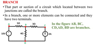
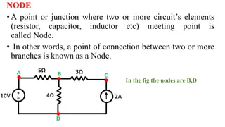
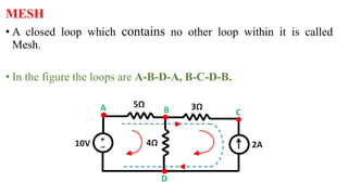
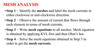
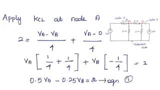
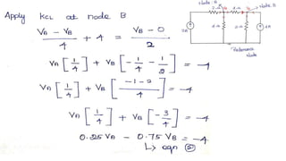
BE8251-Basic Electrical and
Electronics Engineering
MESH AND NODALANALYSIS
BRANCH
•That part or section of a circuit which located between two
junctions are called the branch.
•In a branch, one or more elements can be connected and they
have two terminals.
In the figure AB, BC,
CD,AD, BD are branches.
NODE
• A point or junction where two or more circuit’s elements
(resistor, capacitor, inductor etc) meeting point is
called Node.
• In other words, a point of connection between two or more
branches is known as a Node.
•
• In the fig the nodes are B,D
MESH
• A closed loop which contains no other loop within it is called
Mesh.
• In the figure the loops are A-B-D-A, B-C-D-B.
LOOP
A closed path in a circuit where more than two meshes can
occur is known as Loop
In simple words, It is a closed path in a circuit.
l = b – n + 1
l = no of loops
b = no of branches
n = no of nodes
Contd.,
In the figure the loops are A-B-D-A, B-C-D-B, A-B-C-D-A
MESH ANALYSIS
•Step 1 − Identify the meshes and label the mesh currents in
either clockwise or anti-clockwise direction.
•Step 2 − Observe the amount of current that flows through
each element in terms of mesh currents.
•Step 3 − Write mesh equations to all meshes. Mesh equation
is obtained by applying KVL first and then Ohm’s law.
•Step 4 − Solve the mesh equations obtained in Step 3 in
order to get the mesh currents.
EXAMPLE
NODALANALYSIS
Step: 1 - Identify all nodes.
Step: 2 - Choose a reference node. Identify it with reference
(ground) symbol.
Step: 3 - Assign voltage variables to the other nodes (these
are node voltages.)
Step: 4 - Write a KCL equation for each node (sum the currents
leaving the node and set equal to zero).
Step: 5 - Solve the system of equations from step 4.
EXAMPLE:
Solution:
Thank you

mesh node.pptx

  • 1.
    BE8251-Basic Electrical and ElectronicsEngineering MESH AND NODALANALYSIS
  • 2.
    BRANCH •That part orsection of a circuit which located between two junctions are called the branch. •In a branch, one or more elements can be connected and they have two terminals. In the figure AB, BC, CD,AD, BD are branches.
  • 3.
    NODE • A pointor junction where two or more circuit’s elements (resistor, capacitor, inductor etc) meeting point is called Node. • In other words, a point of connection between two or more branches is known as a Node. • • In the fig the nodes are B,D
  • 4.
    MESH • A closedloop which contains no other loop within it is called Mesh. • In the figure the loops are A-B-D-A, B-C-D-B.
  • 5.
    LOOP A closed pathin a circuit where more than two meshes can occur is known as Loop In simple words, It is a closed path in a circuit. l = b – n + 1 l = no of loops b = no of branches n = no of nodes
  • 6.
    Contd., In the figurethe loops are A-B-D-A, B-C-D-B, A-B-C-D-A
  • 7.
    MESH ANALYSIS •Step 1− Identify the meshes and label the mesh currents in either clockwise or anti-clockwise direction. •Step 2 − Observe the amount of current that flows through each element in terms of mesh currents. •Step 3 − Write mesh equations to all meshes. Mesh equation is obtained by applying KVL first and then Ohm’s law. •Step 4 − Solve the mesh equations obtained in Step 3 in order to get the mesh currents.
  • 8.
  • 14.
    NODALANALYSIS Step: 1 -Identify all nodes. Step: 2 - Choose a reference node. Identify it with reference (ground) symbol. Step: 3 - Assign voltage variables to the other nodes (these are node voltages.) Step: 4 - Write a KCL equation for each node (sum the currents leaving the node and set equal to zero). Step: 5 - Solve the system of equations from step 4.
  • 15.
  • 16.
  • 20.