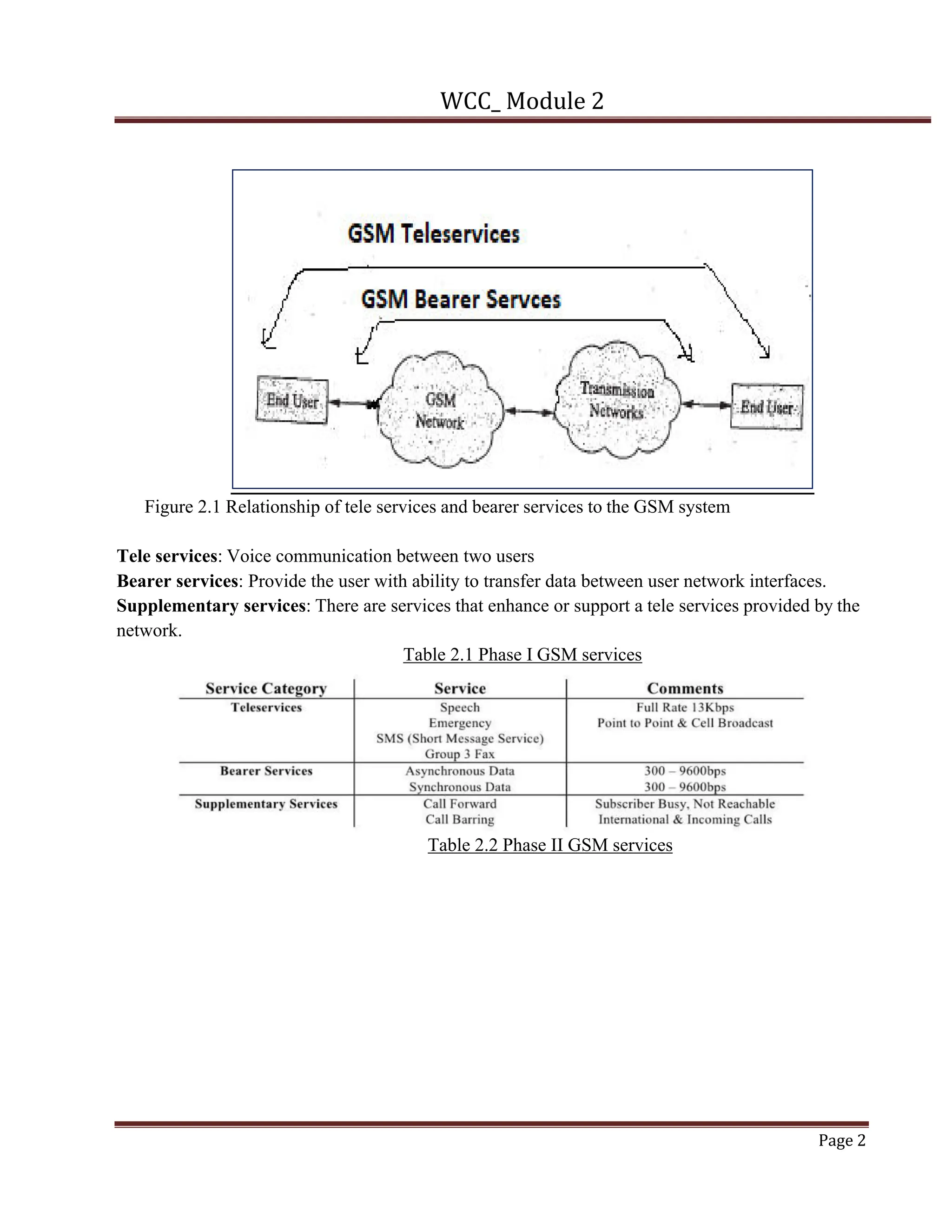
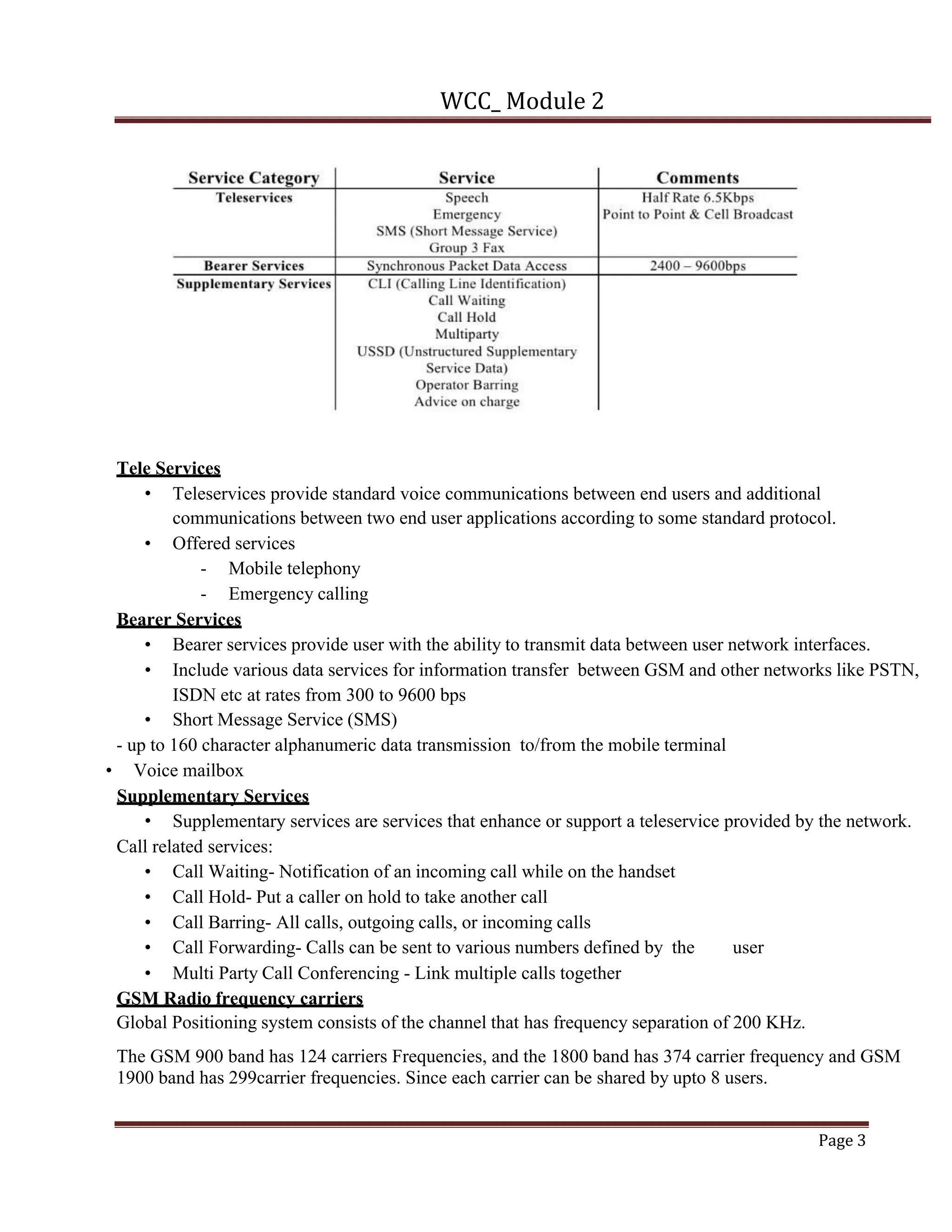
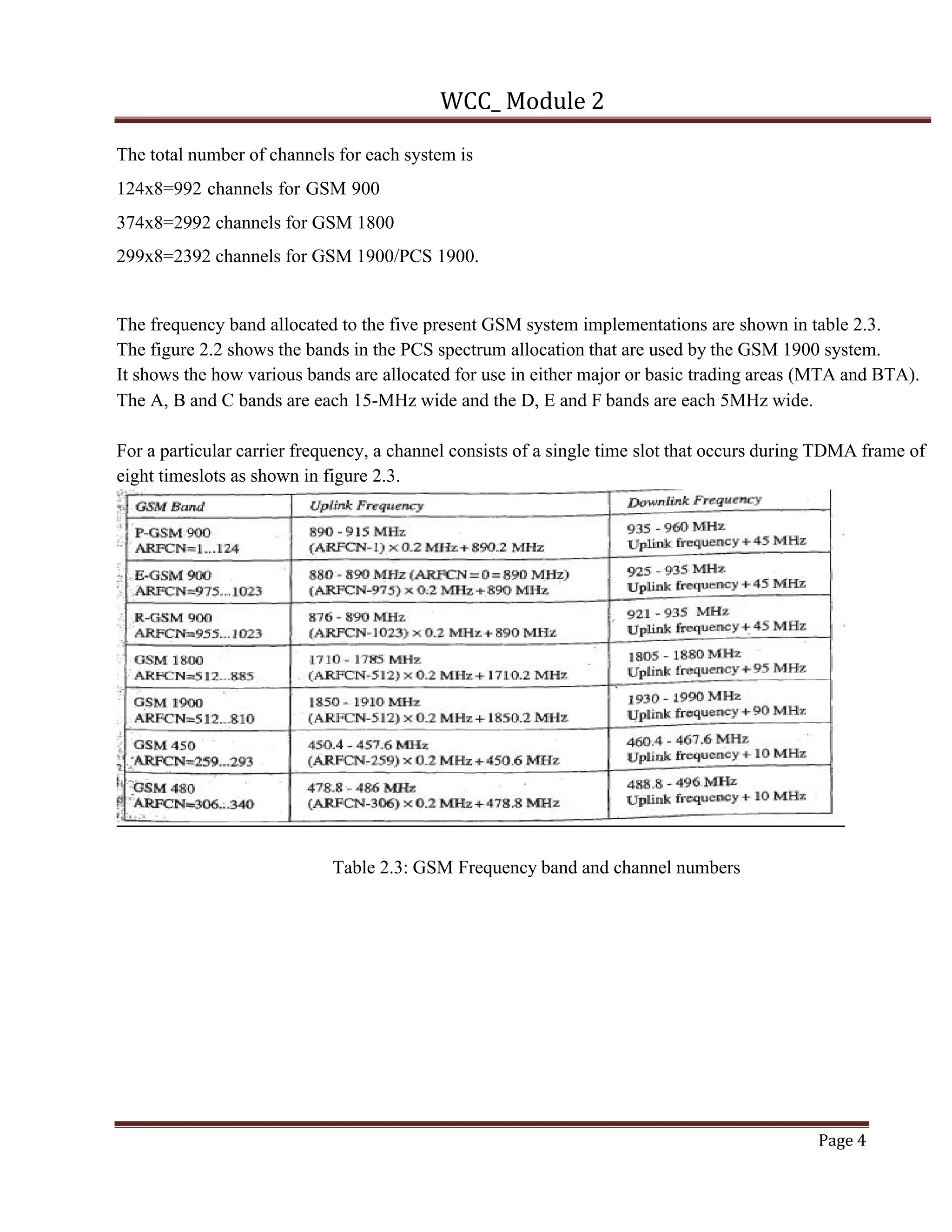
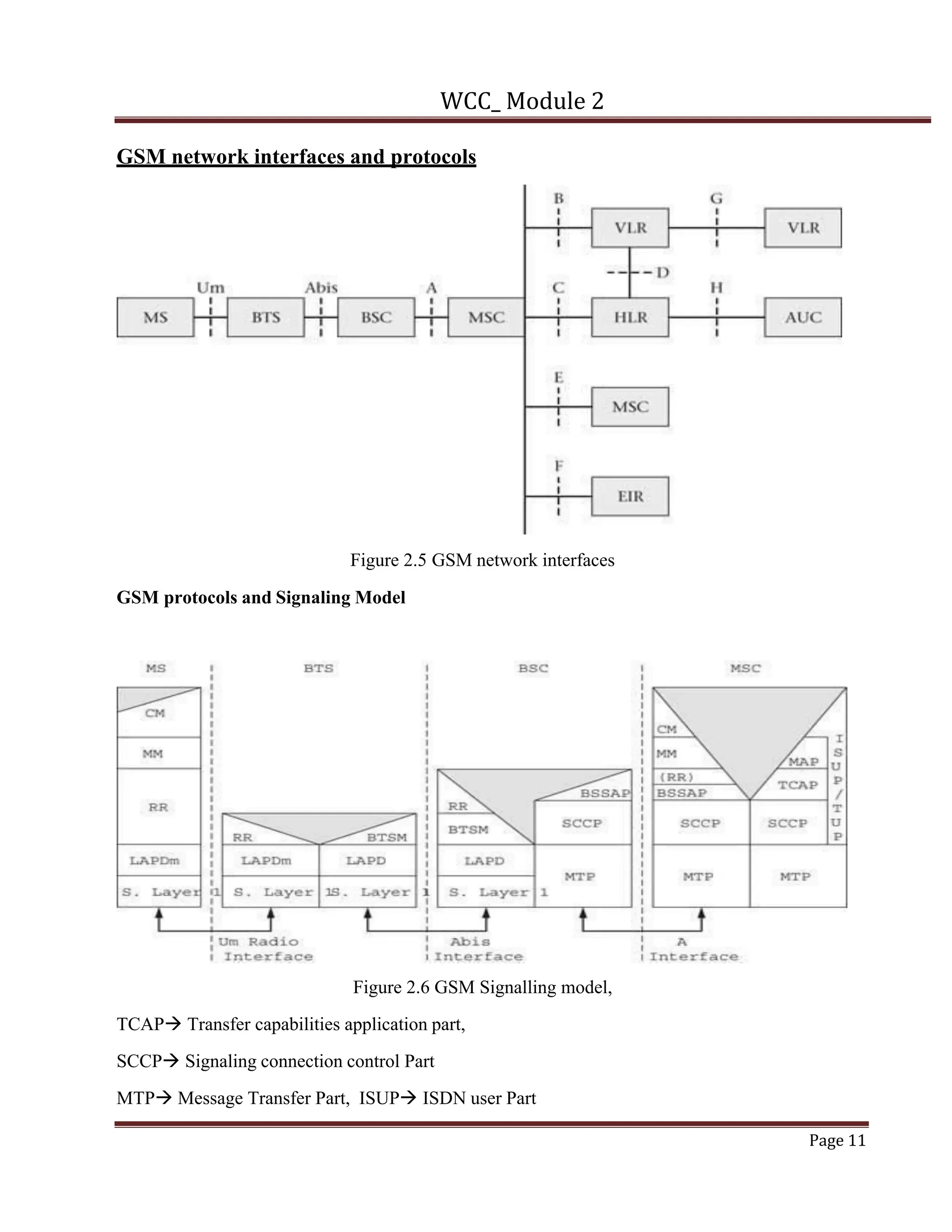
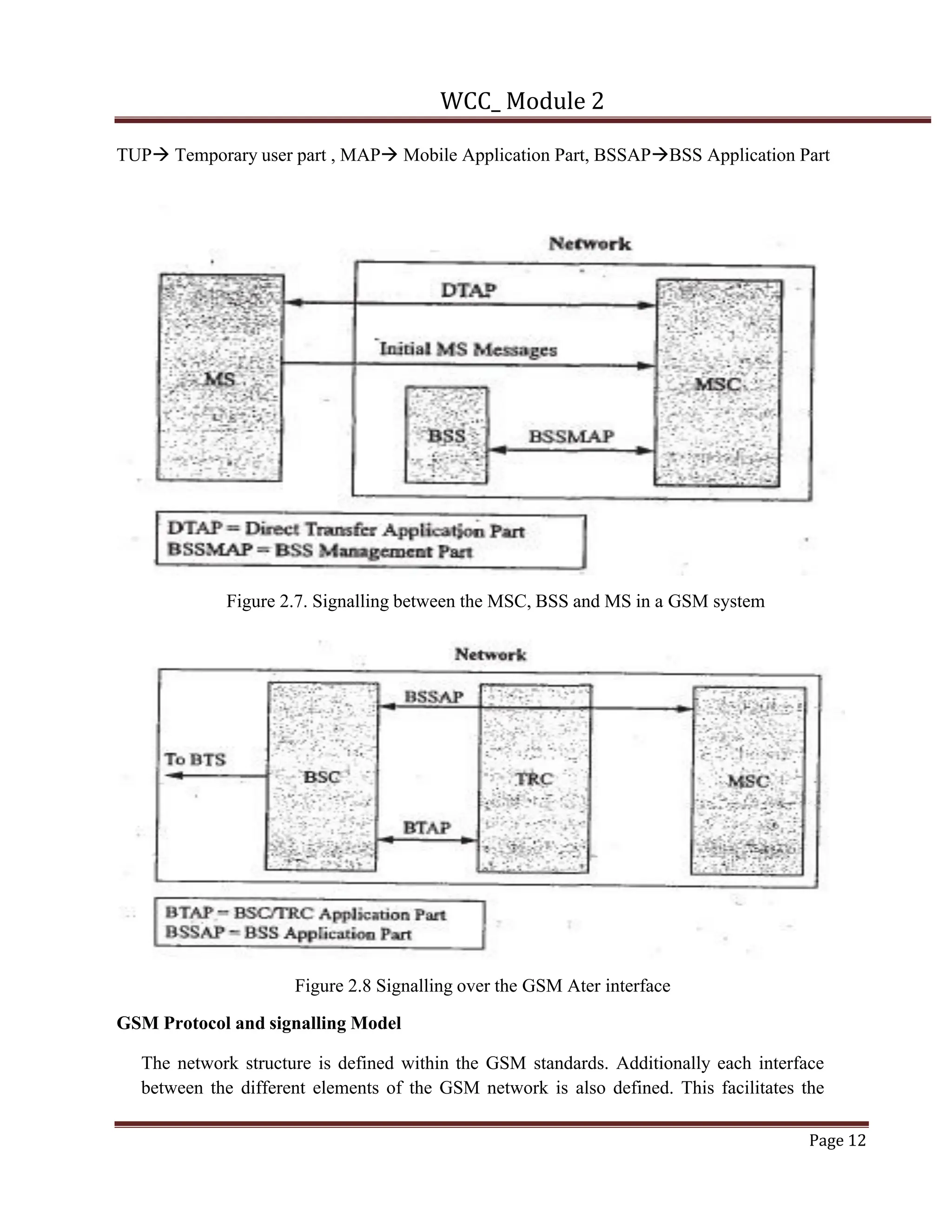
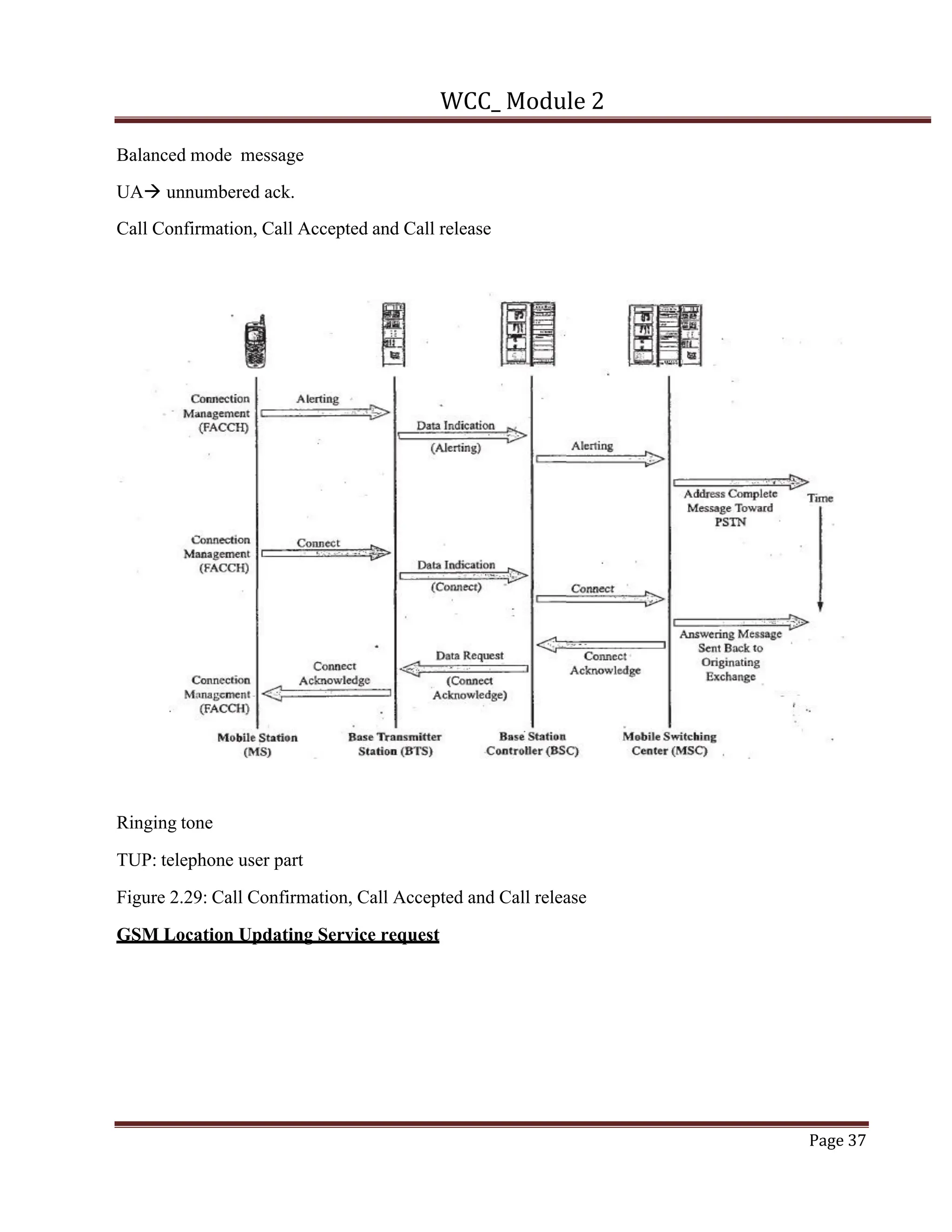
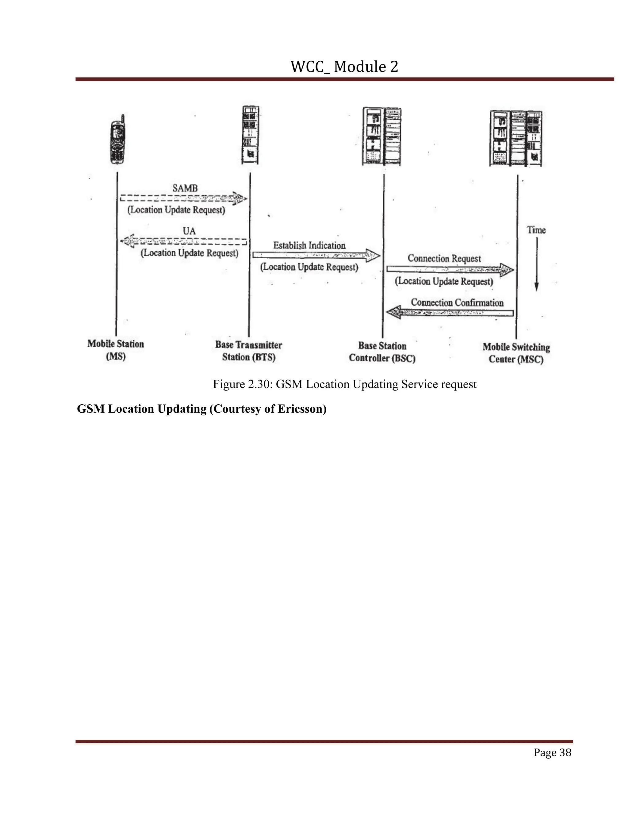
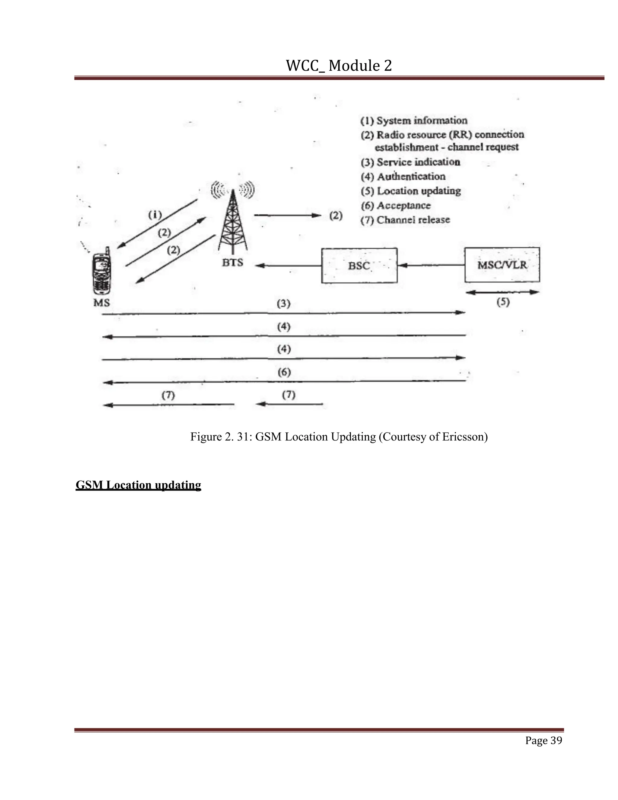
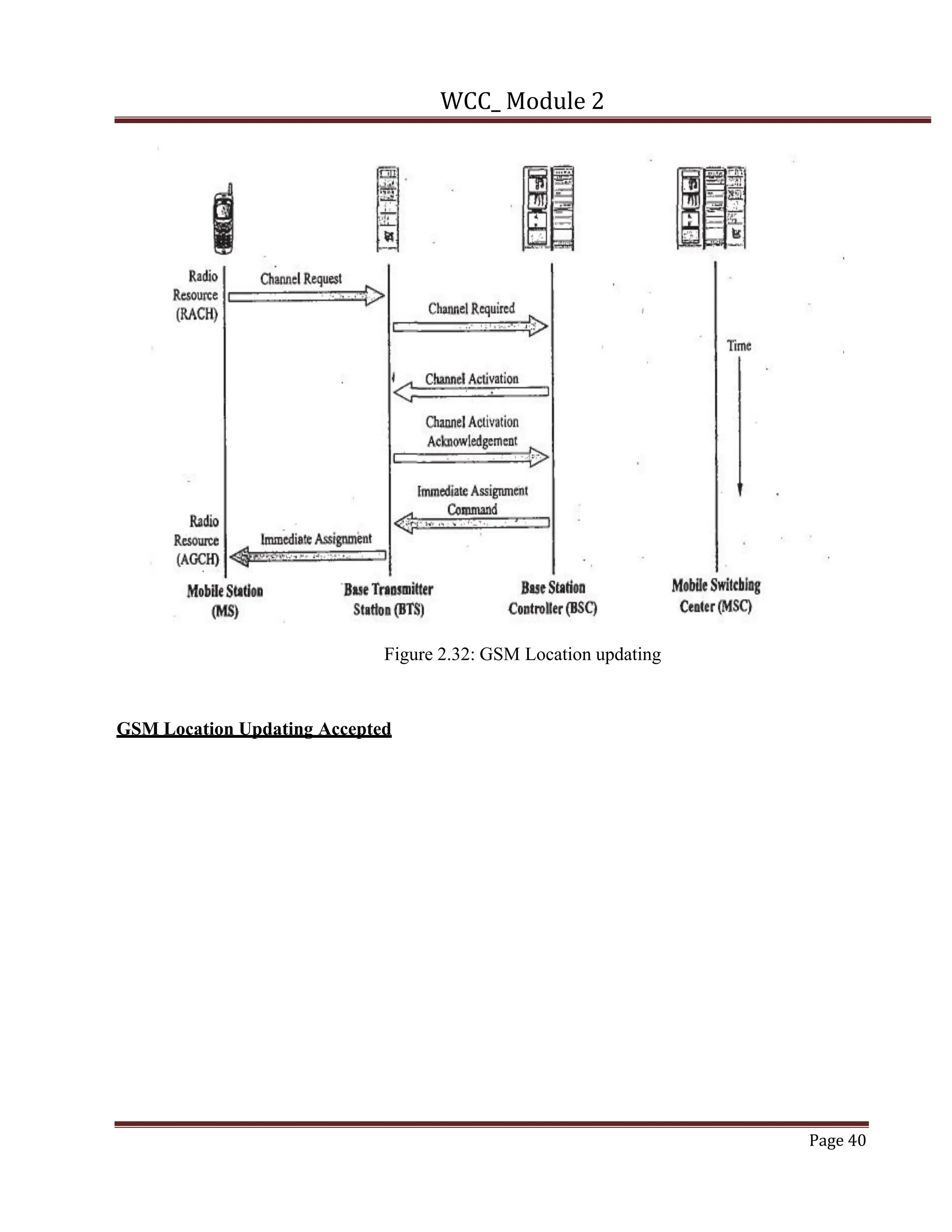
SlideShare a Scribd company logo
1 of 56
Download to read offline
WCC_ Module 2
Page 1
Module-2
GSM and TDMA Technology
GSM System overview – Introduction, GSM Network and System Architecture, GSM Channel Concept.
GSM System Operations – GSM Identities, System Operations –Traffic cases, GSM Infrastructure
Communications (Um Interface)
(Text 2, Part1 and Part 2 of Chapter 5) L1, L2, L3
Module-2
GSM and TDMA Technologies
2.1. Introduction to GSM and TDMA
Global System for Mobile Communications (GSM) services are a standard collection of
applications and features available to mobile phone subscribers all over the world. The
GSM standards are defined by the 3GPP collaboration and implemented in hardware and
software by equipment manufacturers and mobile phone operators. The common standard
makes it possible to use the same phones with different companies' services, or even roam
into different countries. GSM is the world's most dominant mobile phone standard.
• GSM stands for Global System for Mobile Communication.
• It is a digital cellular technology used for transmitting mobile voice and data services
using digital modulation .
GSM: History
• Developed by Group Special Mobile (founded 1982) which was an initiative of CEPT
( Conference of European Post and Telecommunication ).
• Under ETSI, GSM is named as “ Global System for Mobile communication “ in 1989.
• Full set of specifications phase-I became available in 1990.
• Phase 2 of the GSM specifications occurs in 1995. Coverage is extended to rural
areas.
• Development of services evolved into phase 2+, which includes HSPA to GSM.
• HSPA is used in GPRS (General Packet Radio Services) and EDGE (Enhanced data
rates for global evolution .
GSM Services:
The Relationship of tele-services and bearer services to the GSM system are shown in figure 2.1. GSM has
following service namely
• GSM Tele-services
• GSM Bearer or Data Services
• Supplementary services
WCC_ Module 2
Page 2
Figure 2.1 Relationship of tele services and bearer services to the GSM system
Tele services: Voice communication between two users
Bearer services: Provide the user with ability to transfer data between user network interfaces.
Supplementary services: There are services that enhance or support a tele services provided by the
network.
Table 2.1 Phase I GSM services
Table 2.2 Phase II GSM services
WCC_ Module 2
Page 3
Tele Services
• Teleservices provide standard voice communications between end users and additional
communications between two end user applications according to some standard protocol.
• Offered services
- Mobile telephony
- Emergency calling
Bearer Services
• Bearer services provide user with the ability to transmit data between user network interfaces.
• Include various data services for information transfer between GSM and other networks like PSTN,
ISDN etc at rates from 300 to 9600 bps
• Short Message Service (SMS)
- up to 160 character alphanumeric data transmission to/from the mobile terminal
• Voice mailbox
Supplementary Services
• Supplementary services are services that enhance or support a teleservice provided by the network.
Call related services:
• Call Waiting- Notification of an incoming call while on the handset
• Call Hold- Put a caller on hold to take another call
• Call Barring- All calls, outgoing calls, or incoming calls
• Call Forwarding- Calls can be sent to various numbers defined by the user
• Multi Party Call Conferencing - Link multiple calls together
GSM Radio frequency carriers
Global Positioning system consists of the channel that has frequency separation of 200 KHz.
The GSM 900 band has 124 carriers Frequencies, and the 1800 band has 374 carrier frequency and GSM
1900 band has 299carrier frequencies. Since each carrier can be shared by upto 8 users.
WCC_ Module 2
Page 4
The total number of channels for each system is
124x8=992 channels for GSM 900
374x8=2992 channels for GSM 1800
299x8=2392 channels for GSM 1900/PCS 1900.
The frequency band allocated to the five present GSM system implementations are shown in table 2.3.
The figure 2.2 shows the bands in the PCS spectrum allocation that are used by the GSM 1900 system.
It shows the how various bands are allocated for use in either major or basic trading areas (MTA and BTA).
The A, B and C bands are each 15-MHz wide and the D, E and F bands are each 5MHz wide.
For a particular carrier frequency, a channel consists of a single time slot that occurs during TDMA frame of
eight timeslots as shown in figure 2.3.
Table 2.3: GSM Frequency band and channel numbers
WCC_ Module 2
Page 5
Figure 2.2 GSM frequency allocations in the 1900-MHz PCS bands MTAà Major trading area and BTAà
Basic Trading area
Figure 2.3. GSM timeslot in a TDMA Frame
2.2 GSM Network and System Architecture
Figure 2.4: GSM System Architecture
Figure 2.4 shows the basic system architecture for a GSM wireless cellular network
WCC_ Module 2
Page 6
The Major subsystem of GSM Network and System Architecture are
Network Switching Subsystem (NSS), Base Station Subsystem (BSS) and Mobile Station (MS).
The Mobile Station (MS) is the device provides the radio link between the GSM subscriber and
the wireless mobile network.
Mobile Equipment (ME)
The GSM also make use of a Subscriber Identity Module (SIM) or the SIM card that when
inserted into the MS makes it functional.
Base Station Subsystem (BSS)
Base Transceiver Station (BTS)
Base Station Controller (BSC)
Network Switching Subsystem(NSS)
Mobile Switching Center (MSC)
Home Location Register (HLR)
Visitor Location Register (VLR)
Authentication Center (AUC)
Equipment Identity Register (EIR)
Mobile Station (MS)
The Mobile Station is made up of two entities:
• Mobile Equipment (ME)
• Subscriber Identity Module (SIM)
• MS provides subscribers the means to control their access to the PSTN and PDN
• MS can make calls without SIM card
Mobile Equipment
• Portable, vehicle mounted, hand held device
WCC_ Module 2
Page 7
• Uniquely identified by an IMEI number (International Mobile
Equipment Identity)
• Voice and data transmission
• Monitoring power and signal quality of surrounding cells for optimum handover
• Power level : 0.8W – 20 W
160 character long SMS
Subscriber Identity Module (SIM)
• Smart card contains the International Mobile Subscriber Identity (IMSI)
• The mobile MSIISDN Number
• Allows user to send and receive calls and receive other subscribed services
• Protected by a password or SIM PIN (Personal identification Number)
• Can be moved from phone to phone – contains key information to activate the phone
• Security/authentication parameters and also address book contact information (name and
numbers) saved by users.
• SIM card also stores the SMS received by the users and saves.
• Portability of SIM is possible
System Architecture Base Station Subsystem (BSS)
• The BSS is the link between the MS and GSM Mobile switching centre.
• Base Station Subsystem is composed of two parts that communicate across the
standardized Abis interface allowing operation between components made by different
suppliers
• Base Transceiver Station (BTS) and Base Station Controller (BSC)
Base Station Subsystem (BSS)
• The BSS communicate with MS over air interface using protocols
• BSC and BTS communicate using LAPD protocolà Link access protocol for D-
Channels.
• LAPD is the data link protocol used ISDN
WCC_ Module 2
Page 8
Base Transceiver Station (BTS)
• Encodes, encrypts, multiplexes, modulates and feeds the RF signals to the antenna.
• Communicates with Mobile station and BSC. Consists of Transceivers (TRX) units
• It is also called as Radio base station or RBS. RBS is the interface corresponds to the
subscribers MS.
• Provides radio link the MS over the air interface
• Basic components of BTS are radio receivers units, a switching and distribution units, RF
power combining and distribution and
• Environmental control unit, A power system and
• A processing and database storage unit
Base Station Controller (BSC)
• The components of BSC are input and output interface multiplexers, a time slot inter
change group switch, sub rate switch, speech coder/decoders, transcoders and rate
adapters , SS7à signalling system number 7, power supply and distribution units,
Environmental control unit, Various control and signal processor
• Manages Radio resources for BTS
• Assigns Frequency and time slots for all MS’s in its area
• Handles call set up
• Handover for each MS. It communicates with MSC and BTS.
• Its also contains Transcoder controller (TRC). Urban and suburban area traffic are
handled by BSC/TRC
Network Switching Subsystem(NSS)
The system contains the following functional units
• Mobile Switching Center (MSC)
• Home Location Register (HLR)
• Visitor Location Register (VLR)
• Authentication Center (AUC)
WCC_ Module 2
Page 9
• Equipment Identity Register (EIR) also has a switching System may have flexible
number in register and interworking location register to provide more system
functionalities
• Short message services the wireless Switching System we need to have an SMS gateway
MSC(SMS-GMSC) and an SMS interworking MSC(SMS-IWMSC).
• The implementation of GPRS for high-speed data transmission and reception requires
the use of two additional switching elements
• A serving GPRS support node (SGSN)
• A Gateway GPRS support node (GGSN)
Mobile Switching Centre (MSC)
• Heart of the network
• Manages communication between GSM and other networks
• Billing information and collection
• Mobility management
- Registration
- Location Updating
- Inter BSS and inter MSC call handoff
- SS7 Protocol
Home Location Registers (HLR)
• Stores information about each subscriber that belongs to it MSC in permanent and
temporary fashion.
• As soon as mobile subscriber leaves its current local area, the information in the HLR
is updated.
• Ddatabase contains IMSI, MSISDN, prepaid/postpaid, roaming restrictions,
supplementary services.
Visitor Location Registers (VLR)
• Temporary database which updates whenever new MS enters its area, by HLR database.
• Assigns a TMSI (Temporary Mobile Subscriber Identity) to each MS entering the VLR
area which keeps on changing.
WCC_ Module 2
Page 10
• Controls those mobiles roaming in its area.
• Database contains IMSI, MSISDN, Location Area, authentication key.
Authentication Centre (AUC)
• Contains the algorithms for authentication as well as the keys for encryption.
• Protects network operators from fraud.
• Situated in special protected part of the HLR.
Equipment Identity Register (EIR)
• Stores all devices identifications registered for this network.
• Database that is used to track handsets using the IMEI (International Mobile Equipment
Identity)
• Prevents calls from stolen, unauthorised or defective mobile devices
• The AUC and EIR in conjunction with MSC/VLR and HLR provides the additional GSM
network security and facilitates international roaming within GSM network.
• The flexible numbering register (FNR)à provides portability to a subscriber
Operation and Support System and Other Nodes
• The centralized operation of the various units in the system and functions needed to
maintain the subsystems.
• Dynamic monitoring and controlling of the network.
• Functions :
• Configuration management
• Fault report and alarm handling
• Performance supervision/management
• Storage of system software and data
WCC_ Module 2
Page 11
GSM network interfaces and protocols
Figure 2.5 GSM network interfaces
GSM protocols and Signaling Model
Figure 2.6 GSM Signalling model,
TCAPà Transfer capabilities application part,
SCCPà Signaling connection control Part
MTPà Message Transfer Part, ISUPà ISDN user Part
WCC_ Module 2
Page 12
TUPà Temporary user part , MAPà Mobile Application Part, BSSAPàBSS Application Part
Figure 2.7. Signalling between the MSC, BSS and MS in a GSM system
Figure 2.8 Signalling over the GSM Ater interface
GSM Protocol and signalling Model
The network structure is defined within the GSM standards. Additionally each interface
between the different elements of the GSM network is also defined. This facilitates the
WCC_ Module 2
Page 13
information interchanges can take place. It also enables to a large degree that network
elements from different manufacturers can be used.
However as many of these interfaces were not fully defined until after many networks had
been deployed, the level of standardization may not be quite as high as many people might
like.
Figure 2.5 shows the GSM network interfaces and GSM Signalling model is depicted in figure
2.6.
The network structure is defined within the GSM standards.
Additionally each interface between the different elements of the GSM network is also
defined.
This facilitates the information interchanges can take place.
It also enables to a large degree that network elements from different manufacturers can
be used.
Um interface : The "air" or radio interface standard that is used for exchanges between a
mobile (ME) and a base station (BTS / BSC).
For signaling, a modified version of the ISDN LAPD, known as LAPDm is used.
Abis interface : exists between BSC and a BTS, and it has not been totally standardized.
The Abis interface allows control of the radio equipment and radio frequency allocation in
the BTS.
A interface : The A interface is used to provide communication between the BSS and the
MSC.
The interface carries information to enable the channels, timeslots and the like to be
allocated to the mobile equipment's being serviced by the BSSs.
The messaging required within the network to enable handover etc to be undertaken is
carried over the interface.
Although the interfaces for the GSM cellular system may not be as rigorously defined as
many might like, they do at least provide a large element of the definition required,
enabling the functionality of GSM network entities to be defined sufficiently.
Figure 2.7. shows the Signalling between the MSC, BSS and MS in a GSM system
Signalling over the GSM Ater interface is shown in figure 2.8.
WCC_ Module 2
Page 14
2.3 GSM Channel Concept
• The cellular telephone network use various control and traffic channels to carry out
• The operations necessary to allow for the setup of a subscriber radio link for the transmission
of voice or data
• To provide subsequent system support for the subscriber mobility.
• The GSM cellular system is based on the use of TDMA technique to provide additional user capacity
over a limited amount of radio frequency spectrum.
• The GSM system divides the radio link connection time into eight equal and repeating time slots
known as FRAMEs for both uplink and downlink transmissions.
• The timeslots are arranged in sequence and are conventionally numbered 0 to 7
• Each time slot is considered as logical channel.
• Each time slot carry either subscriber traffic or signalling and control information required for the
management of the radio link and other system resources. The figure 2.9 shows the TDMA frame
structure.
Figure 2.9 TDMA time frame structure
Logical Channels.
Broadcast channels
Broadcast control channels.
Frequency Correction channel
Synchronization channels
WCC_ Module 2
Page 15
Logical Channels
§ Carry either subscriber traffic or signaling and control information to facilitate subscriber mobility.
§ Presently, there are three types of traffic channels (TCHS).
The full-rate traffic channel (TCH/F or Bm)
half-rate traffic channel (TCH/H or Lm)
Enhanced full-rate (EFR) traffic
Half-rate traffic channel (TCH/H or Lm)
The half-rate traffic channel (TCH/H or Lm) carries voice encoded at 6.5 kbps or data at rates of 4.8
or 2.4 kbps
With additional overhead bits, the total data rate for TCH/H becomes 11.4 kbps.
Therefore, two conversations or a conversation and a data transfer or two data transfers may be
transmitted over one channel at the same time.
Full-rate traffic channel (TCH/F or Bm)
§ The full-rate traffic channel (TCH/F or Bm) carries one conversation by using one timeslot.
§ The transmitted voice signal is encoded at a 13-kbps rate, but it is sent with additional overhead bits.
§ This information plus additional channel overhead bits yields a final channel data rate of 22.8 kbps.
§ The full-rate traffic channel may also carry data at rates of 14.4, 9.6, 4.8, and 2.4 kbps.
Enhanced full-rate (EFR) traffic channel
Enhanced full-rate (EFR) traffic encodes voice at a 12.2-kbps rate and like TCH/F adds overhead
bits to yield a 22.8 kbps channel data rate.
The EFR channel may also transmit data at the TCH/F rates. More will be said about these channels
later.
The signaling and control channels consist of three channel sub categories:
broadcast channels,
common control channels, and
Dedicated control channels.
WCC_ Module 2
Page 16
Broadcast channels
The GSM cellular system uses broadcast channels (BCHS) provide information to the mobile station
about various system parameters and also information about the location area identity (LAI).
three types BCHs
Broadcast control channel
Frequency correction channel
Synchronization channel
Broadcast control channel
It contains information that needed by MS concerning the cell that it is attached to in order for the MS to be
able to start making or receiving calls, or to start roaming
Frequency correction channel:
It transmits bursts of zeros (this is an un-modulated carrier signal) to the MS.
This signaling is done for two reasons:
i). the MS can use this signal to synchronize itself to the correct frequency and
ii). the MS can verify that this is the BCCH carrier.
Synchronization channel:
§ It transmit the required information for the MS to synchronize itself with the timing within a
particular cell.
§ By listening to the SCH, the MS can learn about the frame number in this cell and about the
BSIC (Base Station Identity Code) of the BTS it is attached to.
§ Using the information transmitted over these three BCHs, the MS can tune to particular base
transceiver system (BTS) and synchronize its timing with the frame structure and timing in that cell.
§ Each time the MS attaches to new BTS, it must listen to these three BCHs
Common Control Channels
§ The common control channels (CCCHS) provide paging messages the MS and a means which the
mobile can request signaling channel that it can use to contact the network.
§ The three CCCHs are
Paging channel
Random access channel
Access Grant channel
WCC_ Module 2
Page 17
Paging channel:
§ It is used by the system to send paging messages to mobiles attached to cell.
§ The mobile will paged whenever the network has an incoming call ready for mobile or some
type of message (e.g., short message, multimedia message) to deliver to the mobile.
§ The information transmitted in the PCH will consist of paging message and the mobile's
identity number.
Random access channel:
§ It is used by the mobile to respond a paging message.
§ If the mobile receives page on the PCH, it will reply on the RACH(Random Access Channel)
with request for signaling channel.
Access Grant channel
It is used by the network to assign a signaling channel to the MS.
After the mobile requests a signaling channel over the RACH (Random Access Channel), the
network will assign a channel to the mobile by transmitting this information over the AGCH
(Access Grant Channel).
The AGCH is only transmitted in the downlink direction.
Dedicated Control Channels
§ These dedicated channels are used for specific call setup, handover, measurement, and short message
delivery functions.
The four DCCHs are
Standalone dedicated control channel
Slow associated control channel.
Fast associated control channel
Cell Broadcast channel
Standalone dedicated control channel:
§ Both the mobile station and the BTS switch over to the network-assigned stand-alone
dedicated control channel (SDCCH) that is assigned over the access grant channel in
response to the mobile's request that has been transmitted over the random access channel.
Slow associated control channel:
§ It is used to transmit information about measurements made by the MS or instructions
from the BTS about the mobile's parameters of operation.
WCC_ Module 2
Page 18
§ In the uplink direction the mobile sends measurements of the received signal strength from
its own BTS (Base Transreceiver Station) and those of neighboring BTSs.
§ In the downlink direction, the MS (Mobile Station) receives information from the BTS
about the mobile's output power level and the timing information.
Fast associated control channel
§ It is used to facilitate the handover operation in a GSM system.
§ If handover is required, the necessary handover signaling information is transmitted instead
of a 20-ms segment of speech over the TCH.
§ This operation is known as "stealing mode" since the time allotted for the voice
conversation is stolen from the system for a short period.
§ The subscriber is usually not aware of this loss of speech since the speech coder in the
mobile simply repeats the last received voice block during this process.
Cell Broadcast channel :
§ It is used to deliver short message service in the downlink direction.
§ It uses the same physical channel as the SDCCH.
GSM speech processing
Figure 2.10 Speech processing
The speech processing of GSM is shown in figure 2.10.
In the mobile, speech is digitised and broken up into 20 ms segments. This process produces
8000 samples of 13 bits per sample per second or 160 samples of 13 bits per 20 ms. The speech
WCC_ Module 2
Page 19
coder is 260 bits per 20 seconds are the 3 kbps whereas the channel coding yields 456 bits per 20
ms or a 22.8 kbps data rate.
Interleaving, ciphering, and burst formatting is yields 156.25 bits per time slot. This yields an
overall data transfer rate of 270.8 kbps over a GSM channel.
The receiver of GSM speech is also shown in figure; signals burst are received and used to
create a channel model.
Channel model is created in the Equaliser where and estimated bit sequence is calculated for a
receiver signal.
After all of the bursts containing information about a 20 ms segment of speech have been
received and deciphered, they are reassembled into 456 bit message. This sequence is then
decoded to detect and correct any errors that occur during transmission.
Timeslots and TDMA Frames
Figure 2.11 Timeslots and TDMA Frames
• GSM has 8 Timeslots in one TDMA frame.
• The System assigns numbers to frames sequentially from
0 to 2,715,648nand the process repeats it self.
• The grouping of successive TDMA frames is known as Hyper frame
TDMA Hyper Frame structure
WCC_ Module 2
Page 20
Figure 2.12 TDMA Hyperframe structure
Figure 2.12 shows frame, super frame, and multiframe and hyper frame structure. A
hyperframe is a multiframe sequence that is composed of 2048 superframes and is largest
time interval in the GSM system (3 hours, 28 minutes, 53 seconds). Every time slot during
a hyperframe has a sequential number (represented by an 11 bit counter) that is composed
of a frame number and a time slot number. This counter allows the hyperframe to
synchronize frequency hopping sequence, encryption processes for voice privacy of
subscribers' conversations. The hyperframe in an IS-136 TDMA system consists of 192
frames.
The basic GSM frame defines the structure upon which all the timing and structure of the
GSM messaging and signalling is based. The fundamental unit of time is called a burst
period and it lasts for approximately 0.577 ms (15/26 ms). Eight of these burst periods are
grouped into what is known as a TDMA frame. This lasts for approximately 4.615 ms
(i.e.120/26 ms) and it forms the basic unit for the definition of logical channels. One
physical channel is one burst period allocated in each TDMA frame.
In simplified terms the base station transmits two types of channel, namely traffic and
control. Accordingly the channel structure is organised into two different types of frame,
WCC_ Module 2
Page 21
one for the traffic on the main traffic carrier frequency, and the other for the control on the
beacon frequency.
GSM multiframe
The GSM frames are grouped together to form multiframes and in this way it is possible to
establish a time schedule for their operation and the network can be synchronised.
There are several GSM multiframe structures:
• Traffic multiframe: The Traffic Channel frames are organised into multiframes
consisting of 26 bursts and taking 120 ms. In a traffic multiframe, 24 bursts are used
for traffic. These are numbered 0 to 11 and 13 to 24. One of the remaining bursts is
then used to accommodate the SACCH, the remaining frame remaining free. The
actual position used alternates between position 12 and 25.
• Control multiframe: the Control Channel multiframe that comprises 51 bursts and
occupies 235.4 ms. This always occurs on the beacon frequency in time slot zero
and it may also occur within slots 2, 4 and 6 of the beacon frequency as well. This
multiframe is subdivided into logical channels which are time-scheduled.
GSM Superframe
Multiframes are then constructed into superframes taking 6.12 seconds. These consist of 51
traffic multiframes or 26 control multiframes. As the traffic multiframes are 26 bursts long
and the control multiframes are 51 bursts long, the different number of traffic and control
multiframes within the superframe, brings them back into line again taking exactly the
same interval.
GSM Hyperframe
Above this 2048 superframes (i.e. 2 to the power 11) are grouped to form one hyperframe
which repeats every 3 hours 28 minutes 53.76 seconds. It is the largest time interval within
the GSM frame structure.
Within the GSM hyperframe there is a counter and every time slot has a unique sequential
number comprising the frame number and time slot number. This is used to maintain
synchronisation of the different scheduled operations with the GSM frame structure. These
include functions such as:
• Frequency hopping: Frequency hopping is a feature that is optional within the
GSM system. It can help reduce interference and fading issues, but for it to work,
the transmitter and receiver must be synchronized so they hop to the same
WCC_ Module 2
Page 22
frequencies at the same time.
• Encryption: The encryption process is synchronised over the GSM hyperframe
period where a counter is used and the encryption process will repeat with each
hyperframe. However, it is unlikely that the cellphone conversation will be over 3
hours and accordingly it is unlikely that security will be compromised as a result.
GSM air interface timeslot
It is shown in figure 2.13, the timeslot has a duration of 3/5200 sec or 577μs or 0.577ms.It transmits
the vice traffic, data or signalling and control messages. The start of a TDMA frame on the uplink is
delayed by three timeslot periods fro the downlink frame as shown in figure 2.14.
Figure 2.13 GSM air interface timeslot
TDMA timing offset between uplink and downlink
Figure 2.14 TDMA timing offset between uplink and downlink
Time slot burst
The transmission of a normal (traffic and control channels) burst and the other types of burst signals are
shown in figure 2.15. GSM Traffic and control signal bursts has five types namely
Normal burst
WCC_ Module 2
Page 23
Frequency correction burst
Synchronization burst
Access burst
Dummy burst
Normal burst
• Here two groups of 57 encrypted bits are transmitted on either side of a training sequence of bits.
• Three tail bits precede the first group of traffic bits and 3 tails bits the last group of traffic bits.
• It has 8.25 bit long guard period (GP) at end where no transmission activity take place.
Frequency correction burst (FCB)
• It is used by the mobile to obtain the frequency synchronization.
• It consists of 142 fixed bits and followed by 3 tail bits.
• It has 8.25 bit long guard period (GP) at end.
• The repetition of FCB by the BTS within the GSM frame structure becomes the frequency
correction channel (FCCH).
Synchronization burst
• It is used by the mobile to obtain the timing synchronization.
• It consists of three tail bit followed by 39 encrypted bits, a 64 bit synchronisation sequence
39 more encrypted bits, 3 tail bits, and the same 8.25 bit long guard period.
• the reputation of synchronising sequence was by the BTS within the GSM frame structure
becomes the synchronising channel(SCH)
Access burst
• It is used by the mobile to facilitate random access request by the mobile and handover operations.
• It consists of 8 tails with followed by 41-bits synchronization sequence , then 36 encrypted bits and 3
3 tail bits.
• The length of the guard bit time period is equal to 252 μs or 68.25 bits.
• The access bus is used on both the Random Access channel on the fast associated control channel
during handover.
Dummy burst
• The dummy bus is transmitted on the radio frequency designated as C0 when no other type of burst
signal is being transmitted.
• It consists of 3 tail bits, 58 mixed bits, a- 26 bits training sequence, 58 more mixed bits, three tail
with the same 8.25 bit longer period.
• The dummy purpose is used to ensure that the base station is always transmitting on the frequency
carrying system information it helps for the power measurement on the strongest BTS.
WCC_ Module 2
Page 24
Figure 2.15 GSM Traffic and control signal bursts
Part II: GSM System Operations
2.4 GSM Identities
Mobile Subscriber ISDN Number (MSISDN)
§ The authentic telephone number of a mobile station is the Mobile Subscriber ISDN Number
(MSISDN). Based on the SIM, a mobile station can have many MSISDNs, as each subscriber is
assigned with a separate MSISDN to their SIM respectively.
§ Listed below is the structure followed by MSISDN categories, as they are defined based on
international ISDN number plan
WCC_ Module 2
Page 25
• Country Code (CC) − Up to 3 decimal places.
• National Destination Code (NDC) − Typically 2-3 decimal places.
• Subscriber Number (SN) − Maximum 10 decimal places.
Network Numbering Plans
GSM has both LAI (Location area identity) and CGI (Cell global Identity)
The LAI is used for MS paging and location updating.
CGI is used for cell identification within a location area.
§ The LAI hierarchy is based on international standard and structured in a unique format as mentioned
below
• Country Code (CC) − 3 decimal places.
• Mobile Network Code (MNC) − 2 decimal places.
• Location Area Code (LAC) − maximum 5 decimal places or maximum twice 8 bits coded in
hexadecimal (LAC < FFFF).
GSM call setup using the MSRN (Mobile Subscriber Roaming Number(Courtesy of Ericsson)
Step1: Initial address message
Step2: Send routing Information
Step3: HLR uses MSISDN to find the subscriber data in the data base.
Step4: Provide Roaming Number
Step5: VLR asks MSC to reserve idle MSRN number
Step6: the MSC/VLR sends the MSRN back to HLR
Step7: HLR sends the MSRN back to GMSC
Step8: GMSC uses the MSRN to route the call to the Correct MSC.
IMSI is used by MSC for final establishment of call.
IMSIà International Mobile Subscriber Identity, GMSCà Gateway Mobile Switching Centre ,MSRNà
Mobile Station Roaming Number
Formulation of GSM MSRN
Mobile Station Roaming Number (MSRN)
§ Mobile Station Roaming Number (MSRN) is an interim location dependent ISDN number, assigned
to a mobile station by a regionally responsible Visitor Location Register (VLR).
§ Figure 2.16 shows the GSM call setup using the MSRN.
§ Using MSRN, the incoming calls are channeled to the MS.
§ The MSRN has the same structure as the MSISDN.
• Country Code (CC) − of the visited network.
• National Destination Code (NDC) − of the visited network.
• Subscriber Number (SN) − This is the number of the serving MSC.
WCC_ Module 2
Page 26
Figure 2.16 GSM call setup using the MSRN
Figure 2.17 Formulation of the GSM MSRN
2.5GSM System Operations (Traffic Cases)
Registration, call setup, and Location Updating
various states of MS
The MS can be powered off, or
card can be removed from the mobile, or
The mobile can be ON but located in an area without service.
In all these cases,
WCC_ Module 2
Page 27
The MS is considered to be in the detached condition. Otherwise, the MS can be powered ON with
in the GSM system and will subsequently enter into an attached relationship with the system.
Registration, call setup, and Location Updating
The mobile can be in either of two states
a (1) the idle state in which the MS has no dedicated channel allocated to it and it just listens to the
broadcast control channels (BCCH) and the paging channels (PCH)
b(2) the active or dedicated state in the MS has a dedicated connection to the GSM network.
While in the attached mode, the MS may change from the idle to the active mode as the result of call
setup, short message service transfers, location updating or supplementary service procedures.
Also if the MS is in the active mode and changes cells, this operation is referred as GSM handover
Call Setup
§ Call setup within a GSM system consists following operations. For either a mobile-originating call
or a mobile-terminating call the following operations need to be performed.
§ For a mobile-terminating call it is necessary to perform an initial additional operation as shown:
1. Interrogation (only for a mobile-terminating call)
2. Radio resource connection establishment.
3. Service request
4. Authentication
5. Ciphering mode setting
6. IMEI number check
7. TMSI (Temporary Mobile Subscriber Identity)allocation
8. Call initiation
9. Assignment of a traffic channel
10. User alerting signaling
11. Call accepted signaling
GSM Interrogation Phase of call setup
For the interrogation operation, initial address message (IAM) comes outside the GSM network
using ISUP (Integrated Services Digital Network User Part ) /TUP(Telephone User Part ) protocols.
WCC_ Module 2
Page 28
GMSCàGateway Mobile Switching Center
Figure 2.18 GSM Interrogation Phase of call setup
Radio resource connection establishment
The MSC/VLR initiates the call set up process by sending a layer 3 paging message to the
appropriate BSC.(IMSI number)
The BSC sends the paging command message to the appropriate BTSs .(IMSI number , the paging
group &channel number)
The BTS sends a paging request message to the MS.
The MS responds to the paging request message by sending channel request message to the BTS.
Detailed messaging during GSM radio resource connection establishment
WCC_ Module 2
Page 29
Figure 2.19: shows the GSM radio resource connection establishment process
Figure 2.20: Radio resource connection establishment
WCC_ Module 2
Page 30
GSM Channel description Messages
Figure 2.21 GSM Channel description Messages
MAIO: mobile allocation Index offset
HSN: Hopping Sequence number
TA: timing Advance, ARFCN: absolute radio-frequency channel number
Service Request
SABM à Set asynchronous balanced mode
UAà unnumbered acknowledgement
Here Circuit connection is established on a
A- interface
WCC_ Module 2
Page 31
Figure 2.22: Service Request
Authentication
GSM Authentication
Operations
128 bit Random Number (RAND)
CKSN: Ciphering Key Sequence
Number
SRES: Signed Responses
Data request and indication is
are used to pass Layer 3 message
A timer is set in MSC/VLR.
If timer expires a second time,
radio resources are released.
WCC_ Module 2
Page 32
IF authentication unsuccessful,
the GSM initiates a Procedure
to identity the MS.
MS is barred or sent Message
that :IMSI is in unknown VLR or
PLMN not allowed.
Figure 2.23: Authentication
Ciphering Mode setting
WCC_ Module 2
Page 33
Figure 2.24: Ciphering Mode setting
Fig: GSM Ciphering Mode setting operations
BSSMAP: contains the value of Kc (key)
CKSN: Ciphering Key Sequence
Number
CKSNà stored in MS
IMSIà stored in VLR
IMEI Check
EIRà Equipment
Identity Register
Three modes
White listed àallowed to use network
Black listed ànot allowed to use network
Grey listed à It is up to the network
operator to use network or not.
WCC_ Module 2
Page 34
TMSI Reallocation
Figure 2.26: TMSI Reallocation
MM message is transmitted over the SDCCH from BTS to MS.
Uplink SDCCH
Call Initiation Procedures
WCC_ Module 2
Page 35
Figure 2.27: Call Initiation Procedures
§ Transmission of setup message transparently from MSC to MS.
§ Downlink SDCCH from BTS to MS.
§ The message is sent transparently from MS to MSC.
§ A timer is started in the MSC/VLR once setup message is sent.
Assignment of a traffic channel
WCC_ Module 2
Page 36
Figure 2.28: Assignment of a traffic channel
DTXà Discontinuous transmission
CICà Circuit Identity Code
Channel type is set to
Bm+ACCH
Full rate TCH+SACCH+FSCCH.
It is sent over SDCCH.
Channel info is present in that.
New channel allocation.
SABMà set asynchronous
WCC_ Module 2
Page 37
Balanced mode message
UAà unnumbered ack.
Call Confirmation, Call Accepted and Call release
Ringing tone
TUP: telephone user part
Figure 2.29: Call Confirmation, Call Accepted and Call release
GSM Location Updating Service request
WCC_ Module 2
Page 38
Figure 2.30: GSM Location Updating Service request
GSM Location Updating (Courtesy of Ericsson)
WCC_ Module 2
Page 39
Figure 2. 31: GSM Location Updating (Courtesy of Ericsson)
GSM Location updating
WCC_ Module 2
Page 40
Figure 2.32: GSM Location updating
GSM Location Updating Accepted
WCC_ Module 2
Page 41
Figure 2.33: GSM Location Updating Accepted
GSM Connection Release
Figure 2.34: GSM Connection Release
WCC_ Module 2
Page 42
GSM IMSI detach (courtesy of Ericsson)
Figure 2.35: GSM IMSI detach
GSM IMSI Attach (courtesy of Ericsson)
Figure 2.36: GSM IMSI Attach
WCC_ Module 2
Page 43
Call handoff
Intra-BSC handover
The process that occurs during the handover intra BSC as follows:
A). During the call, MS will measure the strength and quality of the signal on the
TCH and the signal strength from the neighboring cell. MS to evaluate and assess
the average for each cell.
MS send the results to the BTS measurements every two times in one second cell
not only on their own but also the results of measurements from the BTS
neighboring cell.
B). The BTS will send the results of measurements on the TCH to the BSC. In the
BSC, the function is activated when the placement is required to handover to
another cell.
C). When the handover is done, BSC will check whether the channel had requested
be met by another cell, if not the BSC will be the new BTS to enable TCH.
D). BSC will ask the BTS for a long time to send a message to MS with information
about the frequency, time slot, and the output power for the change.
E). MS choose a new frequency handover and access to the appropriate time slot.
F). When the BTS to detect the handover, the BTS will send the information
contains the physical "timing advance" (the distance between MS to the BTS) to
MS. BTS also inform the BSC to send a "message HO detection" so that point on
the new GS is connected.
G). MS send a "HO complete message."
H). Last time the BTS ordered not to activate the old TCH.
WCC_ Module 2
Inter-BSC handover Figure 2.37 Intra BSC handover
Page 44
WCC_ Module 2
Page 45
In this case BSC1, (old BSC) does not control the better cell which is
the target for the handover. This means that the MSC will be part of
the link procedure between BSC1 and BSC2 (new BSC).
Handover request - BSC1 will use the MSC to send a handover
request to BSC2. The MSC will know which BSC
controls that cell. Activation of new channel - BSC2 will allocate
a TCH in the targetcell and then order the BTS to activate it. The
chosen HO ref. no. will be part of the activation message. The
BTS will acknowledge that the activation has been made.
Handover command - After the activation the new BSC commands
the MS to change to the new channel. The message is sent on
FACCH via the old channel and will contain a full description
of the new channel and the HO ref. no.
3. Handover bursts - When the MS has changed to the new channel,
it will send handover bursts on the new channel. The information
content is the HO ref. no. The bursts are as short as the access bursts.
This is because the MS does not know the new Timing Advance
(TA) value yet. On the detection of the handover bursts, and check
of HO ref. no., the new BTS will send the new TA.
4. Handover complete - Now the MS is ready to continue the
traffic and will send a handover complete message, which will
be addressed to the old BSC asa clear command.
5. Release of old channel - When the old BSC receives the clear
command from the MSC, the BSC knows that the handover was
successful. The BSC orders the BTS to release the TCH and the
BTS will acknowledge.
WCC_ Module 2
Page 46
Figure 2.38 Inter BSC handover
Inter-MSC handover
Handing over a GSM call is a complicated procedure. It is even more so
when the source and target GSM cells are controlled by different MSCs.
WCC_ Module 2
Page 47
The following call flowsanalyze the different steps involved in a inter-
MSC handover:
The source BSC analyzes the signal quality measurement reports and
initiates ahandover.
The source MSC finds that the call needs to be handed over to a cell
controlled by adifferent MSC.
The source MSC and target MSC interact and then command the UT to
move to thenew cell.
The target MSC informs the source MSC when the call has been
successfullyhanded over.
The source MSC releases the radio resources for the call. Note that the
call is stillrouted via the source MSC
WCC_ Module 2
Page 48
Figure 2.39 Inter MSC handover
2.6. GSM Infrastructure Communications (Um Interface)
Review of GSM Protocol Architecture
WCC_ Module 2
Page 49
Layer 3: Networking Layer Operations
Connection Management
Call Control
Short Message Service Support
Supplementary Services Support Layer 1: Physical Layer Operations
Mobility Management
Radio Resource Management
Message format for Layer 3
Layer 2: Data Link Layer Operations
LAPDm Operations
Service Access Points
Data link procedures
Physical Services Required by the Data link Layer
Data link Timer
Layer 1: Physical Layer Operations
A GSM network is a bearer data communication protocol families. Any
protocol stack for data communication, for example TCP/IP, can be
implemented to use a bearer.
GSM protocol architecture is - as for ISDN - structured into three
independent planes .User plane ,Control plane,Management plane
The user plane defines protocols to carry connection oriented voice
and user data. At the radio interface Um, user plane data will be
carried by the logical traffic channel called TCH. The control plane
defines a set of protocols for controlling these connections with
signalling information, for example signalling for connection setup.
Such signalling data is carried over logical control channels called D-
channels (Dm-
channels). As the control channels often have spare capacities, also
user data, the packet oriented SMS data, is transported over these
channels (see Figure gsm8). All logical channels, however, will be
finally multiplexed onto the physical channel.
Management plane function are:
plane management functions related to the system as a whole
including planecoordination
functions related to resources and parameters residing in the layers of the
controland/or user plane.
WCC_ Module 2
Page 50
Management of network element configuration and network
element faults areexamples of management plane functionality
The basic GSM bearer service, Circuit Switched Data (CSD), simply
consists of transmitting and receiving signals representing data instead
of voice across the air interface. Modems are used for the conversion
between data bit streams and modulatedradio signals. Data transmission
is either transparent or non-transparent.
Three layers of interface in GSM
Figure 2.40 Three layers of interface in GSM
Information flow between two nodes in a network.
Eg. Of two network nodes are Between MS and BTS.
Linking of Three layers of interface in GSM
WCC_ Module 2
Page 51
Figure 41. Information flow between two nodes in a network. (Courtesy of ETSI)
Layer 3: Networking Layer Operations
Within GSM network, layer 3 provides the mobile network signalling (MNS)
services for the mobile subscribers applications the MNS operations includes the
following
Connection management functions to establish, maintaining and terminate
circuit-switched connections from the PSTN to a GSM mobile subscriber;
Functions to support Short Message Service to the subscriber
Function to support Supplementary Services and
Functions to support radio resource and mobility management operations
Layer 3: Networking Layer Operations
Within GSM network, layer 3 provides the mobile network signalling (MNS)
services for the mobile subscribers applications the MNS operations includes the
following
WCC_ Module 2
Page 52
Connection management functions to establish, maintaining and terminate
circuit-switched connections from the PSTN to a GSM mobile subscriber;
Functions to support Short Message Service to the subscriber
Function to support Supplementary Services and
Functions to support radio resource and mobility management operations
Distribution of Layer 3 signalling functions (Courtesy of ETSI)
Figure 42. Shows the allocation of the signalling
Functions at Layer 3 for the Um Interface
CCà Connection Management
RRà Radio Resource Management
MMà Mobility Management
Call Control Procedure
WCC_ Module 2
Page 53
Figure 2.43: Call Control Procedure
SAPà Service Access Point
CC-CALL CONTROL
MNCC-SAPà Mobile Network CC-SAP
MMREG-SAPàMN Registration service
MMSMS-SAP
SSà Supplementary Service Support
PDà protocol discriminator
Layer 3: Networking layer operations
Connection management
Mobility management
Radio resource management
Linking of RR, RM and MM in GSM
WCC_ Module 2
Page 54
Figure 2 . 4 4 Linking of RR, RM and MM in GSM
Message format for Layer 3
Figure 2.45: Format of a GSM Layer 3 message
WCC_ Module 2
Page 55
Layer 2: Data Link layer operations
LAPD operations
Service access points
Data link procedures
Physical services required by the Data Link layer
Data link timers
GSM Protocol Entities
Figure 2.46: GSM Protocol Entities
Functional block diagram
of the data link layer in the MS.
Supports three procedures.
1. Data link procedures
2. Data link distribution procedures
3. Random access procedures
Physical services required by the Data link Layer
Frame synchronization
Error protection and correction to ensure a low BER in the data link layer.
Transmission and reception by MS and BTS respectively of random burst,
WCC_ Module 2
Page 56
Physical layer connection that provides for the arrival of bits and frame to the same
order as they were transmitted to the Peer entities on receiving side
Data link timers
There are several system timers and counters used to keep track of the waiting time for the
acknowledgement of a previously transmitted message and the number of times that we
transmission may take place.
The functions and names of this element can be found in the LAPD specification
Layer 1 Physical Layer Operations
The Physical Layer or signalling layer 1 is the actual physical hardware modulation
scheme, channel coding and so forth used to send the bits over the physical channels
on the air interface.
The physical player interfaces with data in clear through the various control channels.
The GSM physical layer operations includes
various channel coding techniques
Bit and frame interleaving of both traffic and control channels
ciphering and
burst formatting and modulation for the transmission of the information and
the complementary functions for the restriction of the transmitted information.
The other functions includes
power control function
synchronization of the receiver self selection strategy and hand over functions

More Related Content

What's hot

Rfid based attendance system
Rfid based attendance systemRfid based attendance system
Rfid based attendance systemA Jay Vardhan
 
RFID attendance system
RFID attendance systemRFID attendance system
RFID attendance systemA.k. Goverdhan
 
3GPP SON Series: Minimization of Drive Testing (MDT)
3GPP SON Series: Minimization of Drive Testing (MDT)3GPP SON Series: Minimization of Drive Testing (MDT)
3GPP SON Series: Minimization of Drive Testing (MDT)3G4G
 
Automatic Electronic Toll Collection System for Transportation by using Passi...
Automatic Electronic Toll Collection System for Transportation by using Passi...Automatic Electronic Toll Collection System for Transportation by using Passi...
Automatic Electronic Toll Collection System for Transportation by using Passi...Associate Professor in VSB Coimbatore
 
Rfid Attadance System ( Project PPt )
Rfid Attadance System ( Project PPt )Rfid Attadance System ( Project PPt )
Rfid Attadance System ( Project PPt )Bhautik Vaghela
 
Ussd call back or UCB
Ussd call back or UCBUssd call back or UCB
Ussd call back or UCBRawand Jaf
 
Signaling security essentials. Ready, steady, 5G!
 Signaling security essentials. Ready, steady, 5G! Signaling security essentials. Ready, steady, 5G!
Signaling security essentials. Ready, steady, 5G!PositiveTechnologies
 
Iot based smart bus tracking system
Iot based smart bus tracking systemIot based smart bus tracking system
Iot based smart bus tracking systemRahul Wagh
 
Vehicle Theft control system
Vehicle Theft control systemVehicle Theft control system
Vehicle Theft control systemAnkush Jamthikar
 
Wireless Personal area networks (Wpan)
Wireless Personal area networks (Wpan)Wireless Personal area networks (Wpan)
Wireless Personal area networks (Wpan)Biplob Orton
 
chapters,reference (1)
chapters,reference (1)chapters,reference (1)
chapters,reference (1)Devika Kunnath
 
Unblocking Stollen Mobile Phones using SS7-MaP vulnerabilities
Unblocking Stollen Mobile Phones using SS7-MaP vulnerabilities Unblocking Stollen Mobile Phones using SS7-MaP vulnerabilities
Unblocking Stollen Mobile Phones using SS7-MaP vulnerabilities Siddharth Rao
 
Intermediate: Vehicle to Everything (V2X) Introduction
Intermediate: Vehicle to Everything (V2X) IntroductionIntermediate: Vehicle to Everything (V2X) Introduction
Intermediate: Vehicle to Everything (V2X) Introduction3G4G
 
Location Based Services
Location Based ServicesLocation Based Services
Location Based ServicesPeter Byrne
 
Rfid based smart attendance system
Rfid based smart attendance systemRfid based smart attendance system
Rfid based smart attendance systemafserfec56
 
GIS Applied to Mobile Technology
GIS Applied to Mobile TechnologyGIS Applied to Mobile Technology
GIS Applied to Mobile TechnologyEsri
 
Global System for Mobile (GSM)
Global System for Mobile (GSM)Global System for Mobile (GSM)
Global System for Mobile (GSM)AakankshaR
 
Lte(long term evolution) 4G LTE
Lte(long term evolution) 4G LTELte(long term evolution) 4G LTE
Lte(long term evolution) 4G LTEkaishik gundu
 

What's hot (20)

Rfid based attendance system
Rfid based attendance systemRfid based attendance system
Rfid based attendance system
 
RFID attendance system
RFID attendance systemRFID attendance system
RFID attendance system
 
3GPP SON Series: Minimization of Drive Testing (MDT)
3GPP SON Series: Minimization of Drive Testing (MDT)3GPP SON Series: Minimization of Drive Testing (MDT)
3GPP SON Series: Minimization of Drive Testing (MDT)
 
Automatic Electronic Toll Collection System for Transportation by using Passi...
Automatic Electronic Toll Collection System for Transportation by using Passi...Automatic Electronic Toll Collection System for Transportation by using Passi...
Automatic Electronic Toll Collection System for Transportation by using Passi...
 
Rfid Attadance System ( Project PPt )
Rfid Attadance System ( Project PPt )Rfid Attadance System ( Project PPt )
Rfid Attadance System ( Project PPt )
 
4G Technology
4G Technology 4G Technology
4G Technology
 
Ussd call back or UCB
Ussd call back or UCBUssd call back or UCB
Ussd call back or UCB
 
Basic Concepts in Wireless LAN
Basic Concepts in Wireless LANBasic Concepts in Wireless LAN
Basic Concepts in Wireless LAN
 
Signaling security essentials. Ready, steady, 5G!
 Signaling security essentials. Ready, steady, 5G! Signaling security essentials. Ready, steady, 5G!
Signaling security essentials. Ready, steady, 5G!
 
Iot based smart bus tracking system
Iot based smart bus tracking systemIot based smart bus tracking system
Iot based smart bus tracking system
 
Vehicle Theft control system
Vehicle Theft control systemVehicle Theft control system
Vehicle Theft control system
 
Wireless Personal area networks (Wpan)
Wireless Personal area networks (Wpan)Wireless Personal area networks (Wpan)
Wireless Personal area networks (Wpan)
 
chapters,reference (1)
chapters,reference (1)chapters,reference (1)
chapters,reference (1)
 
Unblocking Stollen Mobile Phones using SS7-MaP vulnerabilities
Unblocking Stollen Mobile Phones using SS7-MaP vulnerabilities Unblocking Stollen Mobile Phones using SS7-MaP vulnerabilities
Unblocking Stollen Mobile Phones using SS7-MaP vulnerabilities
 
Intermediate: Vehicle to Everything (V2X) Introduction
Intermediate: Vehicle to Everything (V2X) IntroductionIntermediate: Vehicle to Everything (V2X) Introduction
Intermediate: Vehicle to Everything (V2X) Introduction
 
Location Based Services
Location Based ServicesLocation Based Services
Location Based Services
 
Rfid based smart attendance system
Rfid based smart attendance systemRfid based smart attendance system
Rfid based smart attendance system
 
GIS Applied to Mobile Technology
GIS Applied to Mobile TechnologyGIS Applied to Mobile Technology
GIS Applied to Mobile Technology
 
Global System for Mobile (GSM)
Global System for Mobile (GSM)Global System for Mobile (GSM)
Global System for Mobile (GSM)
 
Lte(long term evolution) 4G LTE
Lte(long term evolution) 4G LTELte(long term evolution) 4G LTE
Lte(long term evolution) 4G LTE
 

Similar to Wireless module 2 notes vtu 18ec81 GSM Module

GSM, GPRS and UMTS: easy handbook
GSM, GPRS and UMTS: easy handbookGSM, GPRS and UMTS: easy handbook
GSM, GPRS and UMTS: easy handbookLuca Matteo Ruberto
 
gsm-archtecture.ppt mobile computing ppt
gsm-archtecture.ppt mobile computing pptgsm-archtecture.ppt mobile computing ppt
gsm-archtecture.ppt mobile computing pptkavitamittal18
 
Global system for mobile communication
Global system for mobile communicationGlobal system for mobile communication
Global system for mobile communicationbhartis3
 
Mobile Handset cellular network Telecommunication
Mobile Handset cellular network TelecommunicationMobile Handset cellular network Telecommunication
Mobile Handset cellular network Telecommunicationshaynetk203
 
IT8602 Mobile Communication Unit II
IT8602 Mobile Communication   Unit II IT8602 Mobile Communication   Unit II
IT8602 Mobile Communication Unit II pkaviya
 
2 g 3g_4g - brief
2 g 3g_4g - brief2 g 3g_4g - brief
2 g 3g_4g - briefQuangMan2
 
GSM Network 3G Technologies
GSM Network 3G TechnologiesGSM Network 3G Technologies
GSM Network 3G TechnologiesSajid Marwat
 
presentation on gsm architecture and fixed assignment
presentation on gsm architecture and fixed assignmentpresentation on gsm architecture and fixed assignment
presentation on gsm architecture and fixed assignmentFabiha Ain
 
Digital cellular networks GSM
Digital cellular networks GSMDigital cellular networks GSM
Digital cellular networks GSMRAVIKIRAN ANANDE
 
IT6601 Mobile Computing Unit III
IT6601 Mobile Computing Unit IIIIT6601 Mobile Computing Unit III
IT6601 Mobile Computing Unit IIIpkaviya
 
Journey of Evolution of UMTS and CDMA
Journey of Evolution of UMTS and CDMAJourney of Evolution of UMTS and CDMA
Journey of Evolution of UMTS and CDMANaveen Jakhar, I.T.S
 
GSM TECHNOLOGIES-ARCHITECTURE.pptx
GSM TECHNOLOGIES-ARCHITECTURE.pptxGSM TECHNOLOGIES-ARCHITECTURE.pptx
GSM TECHNOLOGIES-ARCHITECTURE.pptxssuser5c580e1
 
GSM. Global System for Mobile Communication.
GSM. Global System for Mobile Communication.GSM. Global System for Mobile Communication.
GSM. Global System for Mobile Communication.Student
 
105093_633617613676087500 GSM technology.ppt
105093_633617613676087500 GSM technology.ppt105093_633617613676087500 GSM technology.ppt
105093_633617613676087500 GSM technology.pptAkbarpashaShaik3
 
Global system-for-mobile-gsm
Global system-for-mobile-gsmGlobal system-for-mobile-gsm
Global system-for-mobile-gsmMd. Abdur Rahman
 

Similar to Wireless module 2 notes vtu 18ec81 GSM Module (20)

GSM, GPRS and UMTS: easy handbook
GSM, GPRS and UMTS: easy handbookGSM, GPRS and UMTS: easy handbook
GSM, GPRS and UMTS: easy handbook
 
gsm-archtecture.ppt mobile computing ppt
gsm-archtecture.ppt mobile computing pptgsm-archtecture.ppt mobile computing ppt
gsm-archtecture.ppt mobile computing ppt
 
Global system for mobile communication
Global system for mobile communicationGlobal system for mobile communication
Global system for mobile communication
 
Mobile Handset cellular network Telecommunication
Mobile Handset cellular network TelecommunicationMobile Handset cellular network Telecommunication
Mobile Handset cellular network Telecommunication
 
Unit II -Mobile telecommunication systems
Unit II -Mobile telecommunication systemsUnit II -Mobile telecommunication systems
Unit II -Mobile telecommunication systems
 
IT8602 Mobile Communication Unit II
IT8602 Mobile Communication   Unit II IT8602 Mobile Communication   Unit II
IT8602 Mobile Communication Unit II
 
2 g 3g_4g - brief
2 g 3g_4g - brief2 g 3g_4g - brief
2 g 3g_4g - brief
 
GSM Network 3G Technologies
GSM Network 3G TechnologiesGSM Network 3G Technologies
GSM Network 3G Technologies
 
presentation on gsm architecture and fixed assignment
presentation on gsm architecture and fixed assignmentpresentation on gsm architecture and fixed assignment
presentation on gsm architecture and fixed assignment
 
Digital cellular networks GSM
Digital cellular networks GSMDigital cellular networks GSM
Digital cellular networks GSM
 
IT6601 Mobile Computing Unit III
IT6601 Mobile Computing Unit IIIIT6601 Mobile Computing Unit III
IT6601 Mobile Computing Unit III
 
Journey of Evolution of UMTS and CDMA
Journey of Evolution of UMTS and CDMAJourney of Evolution of UMTS and CDMA
Journey of Evolution of UMTS and CDMA
 
GSM TECHNOLOGIES-ARCHITECTURE.pptx
GSM TECHNOLOGIES-ARCHITECTURE.pptxGSM TECHNOLOGIES-ARCHITECTURE.pptx
GSM TECHNOLOGIES-ARCHITECTURE.pptx
 
GSM. Global System for Mobile Communication.
GSM. Global System for Mobile Communication.GSM. Global System for Mobile Communication.
GSM. Global System for Mobile Communication.
 
It6601 mobile computing unit 3
It6601 mobile computing unit 3It6601 mobile computing unit 3
It6601 mobile computing unit 3
 
GSM TECH.pptx
GSM TECH.pptxGSM TECH.pptx
GSM TECH.pptx
 
105093_633617613676087500 GSM technology.ppt
105093_633617613676087500 GSM technology.ppt105093_633617613676087500 GSM technology.ppt
105093_633617613676087500 GSM technology.ppt
 
Global system-for-mobile-gsm
Global system-for-mobile-gsmGlobal system-for-mobile-gsm
Global system-for-mobile-gsm
 
Introduction to gsm
Introduction to gsmIntroduction to gsm
Introduction to gsm
 
Cellular_Net.pdf
Cellular_Net.pdfCellular_Net.pdf
Cellular_Net.pdf
 

Recently uploaded

Porous Ceramics seminar and technical writing
Porous Ceramics seminar and technical writingPorous Ceramics seminar and technical writing
Porous Ceramics seminar and technical writingrakeshbaidya232001
 
Coefficient of Thermal Expansion and their Importance.pptx
Coefficient of Thermal Expansion and their Importance.pptxCoefficient of Thermal Expansion and their Importance.pptx
Coefficient of Thermal Expansion and their Importance.pptxAsutosh Ranjan
 
(ANVI) Koregaon Park Call Girls Just Call 7001035870 [ Cash on Delivery ] Pun...
(ANVI) Koregaon Park Call Girls Just Call 7001035870 [ Cash on Delivery ] Pun...(ANVI) Koregaon Park Call Girls Just Call 7001035870 [ Cash on Delivery ] Pun...
(ANVI) Koregaon Park Call Girls Just Call 7001035870 [ Cash on Delivery ] Pun...ranjana rawat
 
Call Girls Delhi {Jodhpur} 9711199012 high profile service
Call Girls Delhi {Jodhpur} 9711199012 high profile serviceCall Girls Delhi {Jodhpur} 9711199012 high profile service
Call Girls Delhi {Jodhpur} 9711199012 high profile servicerehmti665
 
Model Call Girl in Narela Delhi reach out to us at 🔝8264348440🔝
Model Call Girl in Narela Delhi reach out to us at 🔝8264348440🔝Model Call Girl in Narela Delhi reach out to us at 🔝8264348440🔝
Model Call Girl in Narela Delhi reach out to us at 🔝8264348440🔝soniya singh
 
(RIA) Call Girls Bhosari ( 7001035870 ) HI-Fi Pune Escorts Service
(RIA) Call Girls Bhosari ( 7001035870 ) HI-Fi Pune Escorts Service(RIA) Call Girls Bhosari ( 7001035870 ) HI-Fi Pune Escorts Service
(RIA) Call Girls Bhosari ( 7001035870 ) HI-Fi Pune Escorts Serviceranjana rawat
 
VIP Call Girls Service Hitech City Hyderabad Call +91-8250192130
VIP Call Girls Service Hitech City Hyderabad Call +91-8250192130VIP Call Girls Service Hitech City Hyderabad Call +91-8250192130
VIP Call Girls Service Hitech City Hyderabad Call +91-8250192130Suhani Kapoor
 
MANUFACTURING PROCESS-II UNIT-5 NC MACHINE TOOLS
MANUFACTURING PROCESS-II UNIT-5 NC MACHINE TOOLSMANUFACTURING PROCESS-II UNIT-5 NC MACHINE TOOLS
MANUFACTURING PROCESS-II UNIT-5 NC MACHINE TOOLSSIVASHANKAR N
 
Decoding Kotlin - Your guide to solving the mysterious in Kotlin.pptx
Decoding Kotlin - Your guide to solving the mysterious in Kotlin.pptxDecoding Kotlin - Your guide to solving the mysterious in Kotlin.pptx
Decoding Kotlin - Your guide to solving the mysterious in Kotlin.pptxJoão Esperancinha
 
Gfe Mayur Vihar Call Girls Service WhatsApp -> 9999965857 Available 24x7 ^ De...
Gfe Mayur Vihar Call Girls Service WhatsApp -> 9999965857 Available 24x7 ^ De...Gfe Mayur Vihar Call Girls Service WhatsApp -> 9999965857 Available 24x7 ^ De...
Gfe Mayur Vihar Call Girls Service WhatsApp -> 9999965857 Available 24x7 ^ De...srsj9000
 
Structural Analysis and Design of Foundations: A Comprehensive Handbook for S...
Structural Analysis and Design of Foundations: A Comprehensive Handbook for S...Structural Analysis and Design of Foundations: A Comprehensive Handbook for S...
Structural Analysis and Design of Foundations: A Comprehensive Handbook for S...Dr.Costas Sachpazis
 
(PRIYA) Rajgurunagar Call Girls Just Call 7001035870 [ Cash on Delivery ] Pun...
(PRIYA) Rajgurunagar Call Girls Just Call 7001035870 [ Cash on Delivery ] Pun...(PRIYA) Rajgurunagar Call Girls Just Call 7001035870 [ Cash on Delivery ] Pun...
(PRIYA) Rajgurunagar Call Girls Just Call 7001035870 [ Cash on Delivery ] Pun...ranjana rawat
 
(SHREYA) Chakan Call Girls Just Call 7001035870 [ Cash on Delivery ] Pune Esc...
(SHREYA) Chakan Call Girls Just Call 7001035870 [ Cash on Delivery ] Pune Esc...(SHREYA) Chakan Call Girls Just Call 7001035870 [ Cash on Delivery ] Pune Esc...
(SHREYA) Chakan Call Girls Just Call 7001035870 [ Cash on Delivery ] Pune Esc...ranjana rawat
 
the ladakh protest in leh ladakh 2024 sonam wangchuk.pptx
the ladakh protest in leh ladakh 2024 sonam wangchuk.pptxthe ladakh protest in leh ladakh 2024 sonam wangchuk.pptx
the ladakh protest in leh ladakh 2024 sonam wangchuk.pptxhumanexperienceaaa
 
APPLICATIONS-AC/DC DRIVES-OPERATING CHARACTERISTICS
APPLICATIONS-AC/DC DRIVES-OPERATING CHARACTERISTICSAPPLICATIONS-AC/DC DRIVES-OPERATING CHARACTERISTICS
APPLICATIONS-AC/DC DRIVES-OPERATING CHARACTERISTICSKurinjimalarL3
 

Recently uploaded (20)

9953056974 Call Girls In South Ex, Escorts (Delhi) NCR.pdf
9953056974 Call Girls In South Ex, Escorts (Delhi) NCR.pdf9953056974 Call Girls In South Ex, Escorts (Delhi) NCR.pdf
9953056974 Call Girls In South Ex, Escorts (Delhi) NCR.pdf
 
Porous Ceramics seminar and technical writing
Porous Ceramics seminar and technical writingPorous Ceramics seminar and technical writing
Porous Ceramics seminar and technical writing
 
Coefficient of Thermal Expansion and their Importance.pptx
Coefficient of Thermal Expansion and their Importance.pptxCoefficient of Thermal Expansion and their Importance.pptx
Coefficient of Thermal Expansion and their Importance.pptx
 
DJARUM4D - SLOT GACOR ONLINE | SLOT DEMO ONLINE
DJARUM4D - SLOT GACOR ONLINE | SLOT DEMO ONLINEDJARUM4D - SLOT GACOR ONLINE | SLOT DEMO ONLINE
DJARUM4D - SLOT GACOR ONLINE | SLOT DEMO ONLINE
 
(ANVI) Koregaon Park Call Girls Just Call 7001035870 [ Cash on Delivery ] Pun...
(ANVI) Koregaon Park Call Girls Just Call 7001035870 [ Cash on Delivery ] Pun...(ANVI) Koregaon Park Call Girls Just Call 7001035870 [ Cash on Delivery ] Pun...
(ANVI) Koregaon Park Call Girls Just Call 7001035870 [ Cash on Delivery ] Pun...
 
Call Girls Delhi {Jodhpur} 9711199012 high profile service
Call Girls Delhi {Jodhpur} 9711199012 high profile serviceCall Girls Delhi {Jodhpur} 9711199012 high profile service
Call Girls Delhi {Jodhpur} 9711199012 high profile service
 
Model Call Girl in Narela Delhi reach out to us at 🔝8264348440🔝
Model Call Girl in Narela Delhi reach out to us at 🔝8264348440🔝Model Call Girl in Narela Delhi reach out to us at 🔝8264348440🔝
Model Call Girl in Narela Delhi reach out to us at 🔝8264348440🔝
 
Exploring_Network_Security_with_JA3_by_Rakesh Seal.pptx
Exploring_Network_Security_with_JA3_by_Rakesh Seal.pptxExploring_Network_Security_with_JA3_by_Rakesh Seal.pptx
Exploring_Network_Security_with_JA3_by_Rakesh Seal.pptx
 
★ CALL US 9953330565 ( HOT Young Call Girls In Badarpur delhi NCR
★ CALL US 9953330565 ( HOT Young Call Girls In Badarpur delhi NCR★ CALL US 9953330565 ( HOT Young Call Girls In Badarpur delhi NCR
★ CALL US 9953330565 ( HOT Young Call Girls In Badarpur delhi NCR
 
(RIA) Call Girls Bhosari ( 7001035870 ) HI-Fi Pune Escorts Service
(RIA) Call Girls Bhosari ( 7001035870 ) HI-Fi Pune Escorts Service(RIA) Call Girls Bhosari ( 7001035870 ) HI-Fi Pune Escorts Service
(RIA) Call Girls Bhosari ( 7001035870 ) HI-Fi Pune Escorts Service
 
VIP Call Girls Service Hitech City Hyderabad Call +91-8250192130
VIP Call Girls Service Hitech City Hyderabad Call +91-8250192130VIP Call Girls Service Hitech City Hyderabad Call +91-8250192130
VIP Call Girls Service Hitech City Hyderabad Call +91-8250192130
 
Roadmap to Membership of RICS - Pathways and Routes
Roadmap to Membership of RICS - Pathways and RoutesRoadmap to Membership of RICS - Pathways and Routes
Roadmap to Membership of RICS - Pathways and Routes
 
MANUFACTURING PROCESS-II UNIT-5 NC MACHINE TOOLS
MANUFACTURING PROCESS-II UNIT-5 NC MACHINE TOOLSMANUFACTURING PROCESS-II UNIT-5 NC MACHINE TOOLS
MANUFACTURING PROCESS-II UNIT-5 NC MACHINE TOOLS
 
Decoding Kotlin - Your guide to solving the mysterious in Kotlin.pptx
Decoding Kotlin - Your guide to solving the mysterious in Kotlin.pptxDecoding Kotlin - Your guide to solving the mysterious in Kotlin.pptx
Decoding Kotlin - Your guide to solving the mysterious in Kotlin.pptx
 
Gfe Mayur Vihar Call Girls Service WhatsApp -> 9999965857 Available 24x7 ^ De...
Gfe Mayur Vihar Call Girls Service WhatsApp -> 9999965857 Available 24x7 ^ De...Gfe Mayur Vihar Call Girls Service WhatsApp -> 9999965857 Available 24x7 ^ De...
Gfe Mayur Vihar Call Girls Service WhatsApp -> 9999965857 Available 24x7 ^ De...
 
Structural Analysis and Design of Foundations: A Comprehensive Handbook for S...
Structural Analysis and Design of Foundations: A Comprehensive Handbook for S...Structural Analysis and Design of Foundations: A Comprehensive Handbook for S...
Structural Analysis and Design of Foundations: A Comprehensive Handbook for S...
 
(PRIYA) Rajgurunagar Call Girls Just Call 7001035870 [ Cash on Delivery ] Pun...
(PRIYA) Rajgurunagar Call Girls Just Call 7001035870 [ Cash on Delivery ] Pun...(PRIYA) Rajgurunagar Call Girls Just Call 7001035870 [ Cash on Delivery ] Pun...
(PRIYA) Rajgurunagar Call Girls Just Call 7001035870 [ Cash on Delivery ] Pun...
 
(SHREYA) Chakan Call Girls Just Call 7001035870 [ Cash on Delivery ] Pune Esc...
(SHREYA) Chakan Call Girls Just Call 7001035870 [ Cash on Delivery ] Pune Esc...(SHREYA) Chakan Call Girls Just Call 7001035870 [ Cash on Delivery ] Pune Esc...
(SHREYA) Chakan Call Girls Just Call 7001035870 [ Cash on Delivery ] Pune Esc...
 
the ladakh protest in leh ladakh 2024 sonam wangchuk.pptx
the ladakh protest in leh ladakh 2024 sonam wangchuk.pptxthe ladakh protest in leh ladakh 2024 sonam wangchuk.pptx
the ladakh protest in leh ladakh 2024 sonam wangchuk.pptx
 
APPLICATIONS-AC/DC DRIVES-OPERATING CHARACTERISTICS
APPLICATIONS-AC/DC DRIVES-OPERATING CHARACTERISTICSAPPLICATIONS-AC/DC DRIVES-OPERATING CHARACTERISTICS
APPLICATIONS-AC/DC DRIVES-OPERATING CHARACTERISTICS
 

Wireless module 2 notes vtu 18ec81 GSM Module

  • 1. WCC_ Module 2 Page 1 Module-2 GSM and TDMA Technology GSM System overview – Introduction, GSM Network and System Architecture, GSM Channel Concept. GSM System Operations – GSM Identities, System Operations –Traffic cases, GSM Infrastructure Communications (Um Interface) (Text 2, Part1 and Part 2 of Chapter 5) L1, L2, L3 Module-2 GSM and TDMA Technologies 2.1. Introduction to GSM and TDMA Global System for Mobile Communications (GSM) services are a standard collection of applications and features available to mobile phone subscribers all over the world. The GSM standards are defined by the 3GPP collaboration and implemented in hardware and software by equipment manufacturers and mobile phone operators. The common standard makes it possible to use the same phones with different companies' services, or even roam into different countries. GSM is the world's most dominant mobile phone standard. • GSM stands for Global System for Mobile Communication. • It is a digital cellular technology used for transmitting mobile voice and data services using digital modulation . GSM: History • Developed by Group Special Mobile (founded 1982) which was an initiative of CEPT ( Conference of European Post and Telecommunication ). • Under ETSI, GSM is named as “ Global System for Mobile communication “ in 1989. • Full set of specifications phase-I became available in 1990. • Phase 2 of the GSM specifications occurs in 1995. Coverage is extended to rural areas. • Development of services evolved into phase 2+, which includes HSPA to GSM. • HSPA is used in GPRS (General Packet Radio Services) and EDGE (Enhanced data rates for global evolution . GSM Services: The Relationship of tele-services and bearer services to the GSM system are shown in figure 2.1. GSM has following service namely • GSM Tele-services • GSM Bearer or Data Services • Supplementary services
  • 2. WCC_ Module 2 Page 2 Figure 2.1 Relationship of tele services and bearer services to the GSM system Tele services: Voice communication between two users Bearer services: Provide the user with ability to transfer data between user network interfaces. Supplementary services: There are services that enhance or support a tele services provided by the network. Table 2.1 Phase I GSM services Table 2.2 Phase II GSM services
  • 3. WCC_ Module 2 Page 3 Tele Services • Teleservices provide standard voice communications between end users and additional communications between two end user applications according to some standard protocol. • Offered services - Mobile telephony - Emergency calling Bearer Services • Bearer services provide user with the ability to transmit data between user network interfaces. • Include various data services for information transfer between GSM and other networks like PSTN, ISDN etc at rates from 300 to 9600 bps • Short Message Service (SMS) - up to 160 character alphanumeric data transmission to/from the mobile terminal • Voice mailbox Supplementary Services • Supplementary services are services that enhance or support a teleservice provided by the network. Call related services: • Call Waiting- Notification of an incoming call while on the handset • Call Hold- Put a caller on hold to take another call • Call Barring- All calls, outgoing calls, or incoming calls • Call Forwarding- Calls can be sent to various numbers defined by the user • Multi Party Call Conferencing - Link multiple calls together GSM Radio frequency carriers Global Positioning system consists of the channel that has frequency separation of 200 KHz. The GSM 900 band has 124 carriers Frequencies, and the 1800 band has 374 carrier frequency and GSM 1900 band has 299carrier frequencies. Since each carrier can be shared by upto 8 users.
  • 4. WCC_ Module 2 Page 4 The total number of channels for each system is 124x8=992 channels for GSM 900 374x8=2992 channels for GSM 1800 299x8=2392 channels for GSM 1900/PCS 1900. The frequency band allocated to the five present GSM system implementations are shown in table 2.3. The figure 2.2 shows the bands in the PCS spectrum allocation that are used by the GSM 1900 system. It shows the how various bands are allocated for use in either major or basic trading areas (MTA and BTA). The A, B and C bands are each 15-MHz wide and the D, E and F bands are each 5MHz wide. For a particular carrier frequency, a channel consists of a single time slot that occurs during TDMA frame of eight timeslots as shown in figure 2.3. Table 2.3: GSM Frequency band and channel numbers
  • 5. WCC_ Module 2 Page 5 Figure 2.2 GSM frequency allocations in the 1900-MHz PCS bands MTAà Major trading area and BTAà Basic Trading area Figure 2.3. GSM timeslot in a TDMA Frame 2.2 GSM Network and System Architecture Figure 2.4: GSM System Architecture Figure 2.4 shows the basic system architecture for a GSM wireless cellular network
  • 6. WCC_ Module 2 Page 6 The Major subsystem of GSM Network and System Architecture are Network Switching Subsystem (NSS), Base Station Subsystem (BSS) and Mobile Station (MS). The Mobile Station (MS) is the device provides the radio link between the GSM subscriber and the wireless mobile network. Mobile Equipment (ME) The GSM also make use of a Subscriber Identity Module (SIM) or the SIM card that when inserted into the MS makes it functional. Base Station Subsystem (BSS) Base Transceiver Station (BTS) Base Station Controller (BSC) Network Switching Subsystem(NSS) Mobile Switching Center (MSC) Home Location Register (HLR) Visitor Location Register (VLR) Authentication Center (AUC) Equipment Identity Register (EIR) Mobile Station (MS) The Mobile Station is made up of two entities: • Mobile Equipment (ME) • Subscriber Identity Module (SIM) • MS provides subscribers the means to control their access to the PSTN and PDN • MS can make calls without SIM card Mobile Equipment • Portable, vehicle mounted, hand held device
  • 7. WCC_ Module 2 Page 7 • Uniquely identified by an IMEI number (International Mobile Equipment Identity) • Voice and data transmission • Monitoring power and signal quality of surrounding cells for optimum handover • Power level : 0.8W – 20 W 160 character long SMS Subscriber Identity Module (SIM) • Smart card contains the International Mobile Subscriber Identity (IMSI) • The mobile MSIISDN Number • Allows user to send and receive calls and receive other subscribed services • Protected by a password or SIM PIN (Personal identification Number) • Can be moved from phone to phone – contains key information to activate the phone • Security/authentication parameters and also address book contact information (name and numbers) saved by users. • SIM card also stores the SMS received by the users and saves. • Portability of SIM is possible System Architecture Base Station Subsystem (BSS) • The BSS is the link between the MS and GSM Mobile switching centre. • Base Station Subsystem is composed of two parts that communicate across the standardized Abis interface allowing operation between components made by different suppliers • Base Transceiver Station (BTS) and Base Station Controller (BSC) Base Station Subsystem (BSS) • The BSS communicate with MS over air interface using protocols • BSC and BTS communicate using LAPD protocolà Link access protocol for D- Channels. • LAPD is the data link protocol used ISDN
  • 8. WCC_ Module 2 Page 8 Base Transceiver Station (BTS) • Encodes, encrypts, multiplexes, modulates and feeds the RF signals to the antenna. • Communicates with Mobile station and BSC. Consists of Transceivers (TRX) units • It is also called as Radio base station or RBS. RBS is the interface corresponds to the subscribers MS. • Provides radio link the MS over the air interface • Basic components of BTS are radio receivers units, a switching and distribution units, RF power combining and distribution and • Environmental control unit, A power system and • A processing and database storage unit Base Station Controller (BSC) • The components of BSC are input and output interface multiplexers, a time slot inter change group switch, sub rate switch, speech coder/decoders, transcoders and rate adapters , SS7à signalling system number 7, power supply and distribution units, Environmental control unit, Various control and signal processor • Manages Radio resources for BTS • Assigns Frequency and time slots for all MS’s in its area • Handles call set up • Handover for each MS. It communicates with MSC and BTS. • Its also contains Transcoder controller (TRC). Urban and suburban area traffic are handled by BSC/TRC Network Switching Subsystem(NSS) The system contains the following functional units • Mobile Switching Center (MSC) • Home Location Register (HLR) • Visitor Location Register (VLR) • Authentication Center (AUC)
  • 9. WCC_ Module 2 Page 9 • Equipment Identity Register (EIR) also has a switching System may have flexible number in register and interworking location register to provide more system functionalities • Short message services the wireless Switching System we need to have an SMS gateway MSC(SMS-GMSC) and an SMS interworking MSC(SMS-IWMSC). • The implementation of GPRS for high-speed data transmission and reception requires the use of two additional switching elements • A serving GPRS support node (SGSN) • A Gateway GPRS support node (GGSN) Mobile Switching Centre (MSC) • Heart of the network • Manages communication between GSM and other networks • Billing information and collection • Mobility management - Registration - Location Updating - Inter BSS and inter MSC call handoff - SS7 Protocol Home Location Registers (HLR) • Stores information about each subscriber that belongs to it MSC in permanent and temporary fashion. • As soon as mobile subscriber leaves its current local area, the information in the HLR is updated. • Ddatabase contains IMSI, MSISDN, prepaid/postpaid, roaming restrictions, supplementary services. Visitor Location Registers (VLR) • Temporary database which updates whenever new MS enters its area, by HLR database. • Assigns a TMSI (Temporary Mobile Subscriber Identity) to each MS entering the VLR area which keeps on changing.
  • 10. WCC_ Module 2 Page 10 • Controls those mobiles roaming in its area. • Database contains IMSI, MSISDN, Location Area, authentication key. Authentication Centre (AUC) • Contains the algorithms for authentication as well as the keys for encryption. • Protects network operators from fraud. • Situated in special protected part of the HLR. Equipment Identity Register (EIR) • Stores all devices identifications registered for this network. • Database that is used to track handsets using the IMEI (International Mobile Equipment Identity) • Prevents calls from stolen, unauthorised or defective mobile devices • The AUC and EIR in conjunction with MSC/VLR and HLR provides the additional GSM network security and facilitates international roaming within GSM network. • The flexible numbering register (FNR)à provides portability to a subscriber Operation and Support System and Other Nodes • The centralized operation of the various units in the system and functions needed to maintain the subsystems. • Dynamic monitoring and controlling of the network. • Functions : • Configuration management • Fault report and alarm handling • Performance supervision/management • Storage of system software and data
  • 11. WCC_ Module 2 Page 11 GSM network interfaces and protocols Figure 2.5 GSM network interfaces GSM protocols and Signaling Model Figure 2.6 GSM Signalling model, TCAPà Transfer capabilities application part, SCCPà Signaling connection control Part MTPà Message Transfer Part, ISUPà ISDN user Part
  • 12. WCC_ Module 2 Page 12 TUPà Temporary user part , MAPà Mobile Application Part, BSSAPàBSS Application Part Figure 2.7. Signalling between the MSC, BSS and MS in a GSM system Figure 2.8 Signalling over the GSM Ater interface GSM Protocol and signalling Model The network structure is defined within the GSM standards. Additionally each interface between the different elements of the GSM network is also defined. This facilitates the
  • 13. WCC_ Module 2 Page 13 information interchanges can take place. It also enables to a large degree that network elements from different manufacturers can be used. However as many of these interfaces were not fully defined until after many networks had been deployed, the level of standardization may not be quite as high as many people might like. Figure 2.5 shows the GSM network interfaces and GSM Signalling model is depicted in figure 2.6. The network structure is defined within the GSM standards. Additionally each interface between the different elements of the GSM network is also defined. This facilitates the information interchanges can take place. It also enables to a large degree that network elements from different manufacturers can be used. Um interface : The "air" or radio interface standard that is used for exchanges between a mobile (ME) and a base station (BTS / BSC). For signaling, a modified version of the ISDN LAPD, known as LAPDm is used. Abis interface : exists between BSC and a BTS, and it has not been totally standardized. The Abis interface allows control of the radio equipment and radio frequency allocation in the BTS. A interface : The A interface is used to provide communication between the BSS and the MSC. The interface carries information to enable the channels, timeslots and the like to be allocated to the mobile equipment's being serviced by the BSSs. The messaging required within the network to enable handover etc to be undertaken is carried over the interface. Although the interfaces for the GSM cellular system may not be as rigorously defined as many might like, they do at least provide a large element of the definition required, enabling the functionality of GSM network entities to be defined sufficiently. Figure 2.7. shows the Signalling between the MSC, BSS and MS in a GSM system Signalling over the GSM Ater interface is shown in figure 2.8.
  • 14. WCC_ Module 2 Page 14 2.3 GSM Channel Concept • The cellular telephone network use various control and traffic channels to carry out • The operations necessary to allow for the setup of a subscriber radio link for the transmission of voice or data • To provide subsequent system support for the subscriber mobility. • The GSM cellular system is based on the use of TDMA technique to provide additional user capacity over a limited amount of radio frequency spectrum. • The GSM system divides the radio link connection time into eight equal and repeating time slots known as FRAMEs for both uplink and downlink transmissions. • The timeslots are arranged in sequence and are conventionally numbered 0 to 7 • Each time slot is considered as logical channel. • Each time slot carry either subscriber traffic or signalling and control information required for the management of the radio link and other system resources. The figure 2.9 shows the TDMA frame structure. Figure 2.9 TDMA time frame structure Logical Channels. Broadcast channels Broadcast control channels. Frequency Correction channel Synchronization channels
  • 15. WCC_ Module 2 Page 15 Logical Channels § Carry either subscriber traffic or signaling and control information to facilitate subscriber mobility. § Presently, there are three types of traffic channels (TCHS). The full-rate traffic channel (TCH/F or Bm) half-rate traffic channel (TCH/H or Lm) Enhanced full-rate (EFR) traffic Half-rate traffic channel (TCH/H or Lm) The half-rate traffic channel (TCH/H or Lm) carries voice encoded at 6.5 kbps or data at rates of 4.8 or 2.4 kbps With additional overhead bits, the total data rate for TCH/H becomes 11.4 kbps. Therefore, two conversations or a conversation and a data transfer or two data transfers may be transmitted over one channel at the same time. Full-rate traffic channel (TCH/F or Bm) § The full-rate traffic channel (TCH/F or Bm) carries one conversation by using one timeslot. § The transmitted voice signal is encoded at a 13-kbps rate, but it is sent with additional overhead bits. § This information plus additional channel overhead bits yields a final channel data rate of 22.8 kbps. § The full-rate traffic channel may also carry data at rates of 14.4, 9.6, 4.8, and 2.4 kbps. Enhanced full-rate (EFR) traffic channel Enhanced full-rate (EFR) traffic encodes voice at a 12.2-kbps rate and like TCH/F adds overhead bits to yield a 22.8 kbps channel data rate. The EFR channel may also transmit data at the TCH/F rates. More will be said about these channels later. The signaling and control channels consist of three channel sub categories: broadcast channels, common control channels, and Dedicated control channels.
  • 16. WCC_ Module 2 Page 16 Broadcast channels The GSM cellular system uses broadcast channels (BCHS) provide information to the mobile station about various system parameters and also information about the location area identity (LAI). three types BCHs Broadcast control channel Frequency correction channel Synchronization channel Broadcast control channel It contains information that needed by MS concerning the cell that it is attached to in order for the MS to be able to start making or receiving calls, or to start roaming Frequency correction channel: It transmits bursts of zeros (this is an un-modulated carrier signal) to the MS. This signaling is done for two reasons: i). the MS can use this signal to synchronize itself to the correct frequency and ii). the MS can verify that this is the BCCH carrier. Synchronization channel: § It transmit the required information for the MS to synchronize itself with the timing within a particular cell. § By listening to the SCH, the MS can learn about the frame number in this cell and about the BSIC (Base Station Identity Code) of the BTS it is attached to. § Using the information transmitted over these three BCHs, the MS can tune to particular base transceiver system (BTS) and synchronize its timing with the frame structure and timing in that cell. § Each time the MS attaches to new BTS, it must listen to these three BCHs Common Control Channels § The common control channels (CCCHS) provide paging messages the MS and a means which the mobile can request signaling channel that it can use to contact the network. § The three CCCHs are Paging channel Random access channel Access Grant channel
  • 17. WCC_ Module 2 Page 17 Paging channel: § It is used by the system to send paging messages to mobiles attached to cell. § The mobile will paged whenever the network has an incoming call ready for mobile or some type of message (e.g., short message, multimedia message) to deliver to the mobile. § The information transmitted in the PCH will consist of paging message and the mobile's identity number. Random access channel: § It is used by the mobile to respond a paging message. § If the mobile receives page on the PCH, it will reply on the RACH(Random Access Channel) with request for signaling channel. Access Grant channel It is used by the network to assign a signaling channel to the MS. After the mobile requests a signaling channel over the RACH (Random Access Channel), the network will assign a channel to the mobile by transmitting this information over the AGCH (Access Grant Channel). The AGCH is only transmitted in the downlink direction. Dedicated Control Channels § These dedicated channels are used for specific call setup, handover, measurement, and short message delivery functions. The four DCCHs are Standalone dedicated control channel Slow associated control channel. Fast associated control channel Cell Broadcast channel Standalone dedicated control channel: § Both the mobile station and the BTS switch over to the network-assigned stand-alone dedicated control channel (SDCCH) that is assigned over the access grant channel in response to the mobile's request that has been transmitted over the random access channel. Slow associated control channel: § It is used to transmit information about measurements made by the MS or instructions from the BTS about the mobile's parameters of operation.
  • 18. WCC_ Module 2 Page 18 § In the uplink direction the mobile sends measurements of the received signal strength from its own BTS (Base Transreceiver Station) and those of neighboring BTSs. § In the downlink direction, the MS (Mobile Station) receives information from the BTS about the mobile's output power level and the timing information. Fast associated control channel § It is used to facilitate the handover operation in a GSM system. § If handover is required, the necessary handover signaling information is transmitted instead of a 20-ms segment of speech over the TCH. § This operation is known as "stealing mode" since the time allotted for the voice conversation is stolen from the system for a short period. § The subscriber is usually not aware of this loss of speech since the speech coder in the mobile simply repeats the last received voice block during this process. Cell Broadcast channel : § It is used to deliver short message service in the downlink direction. § It uses the same physical channel as the SDCCH. GSM speech processing Figure 2.10 Speech processing The speech processing of GSM is shown in figure 2.10. In the mobile, speech is digitised and broken up into 20 ms segments. This process produces 8000 samples of 13 bits per sample per second or 160 samples of 13 bits per 20 ms. The speech
  • 19. WCC_ Module 2 Page 19 coder is 260 bits per 20 seconds are the 3 kbps whereas the channel coding yields 456 bits per 20 ms or a 22.8 kbps data rate. Interleaving, ciphering, and burst formatting is yields 156.25 bits per time slot. This yields an overall data transfer rate of 270.8 kbps over a GSM channel. The receiver of GSM speech is also shown in figure; signals burst are received and used to create a channel model. Channel model is created in the Equaliser where and estimated bit sequence is calculated for a receiver signal. After all of the bursts containing information about a 20 ms segment of speech have been received and deciphered, they are reassembled into 456 bit message. This sequence is then decoded to detect and correct any errors that occur during transmission. Timeslots and TDMA Frames Figure 2.11 Timeslots and TDMA Frames • GSM has 8 Timeslots in one TDMA frame. • The System assigns numbers to frames sequentially from 0 to 2,715,648nand the process repeats it self. • The grouping of successive TDMA frames is known as Hyper frame TDMA Hyper Frame structure
  • 20. WCC_ Module 2 Page 20 Figure 2.12 TDMA Hyperframe structure Figure 2.12 shows frame, super frame, and multiframe and hyper frame structure. A hyperframe is a multiframe sequence that is composed of 2048 superframes and is largest time interval in the GSM system (3 hours, 28 minutes, 53 seconds). Every time slot during a hyperframe has a sequential number (represented by an 11 bit counter) that is composed of a frame number and a time slot number. This counter allows the hyperframe to synchronize frequency hopping sequence, encryption processes for voice privacy of subscribers' conversations. The hyperframe in an IS-136 TDMA system consists of 192 frames. The basic GSM frame defines the structure upon which all the timing and structure of the GSM messaging and signalling is based. The fundamental unit of time is called a burst period and it lasts for approximately 0.577 ms (15/26 ms). Eight of these burst periods are grouped into what is known as a TDMA frame. This lasts for approximately 4.615 ms (i.e.120/26 ms) and it forms the basic unit for the definition of logical channels. One physical channel is one burst period allocated in each TDMA frame. In simplified terms the base station transmits two types of channel, namely traffic and control. Accordingly the channel structure is organised into two different types of frame,
  • 21. WCC_ Module 2 Page 21 one for the traffic on the main traffic carrier frequency, and the other for the control on the beacon frequency. GSM multiframe The GSM frames are grouped together to form multiframes and in this way it is possible to establish a time schedule for their operation and the network can be synchronised. There are several GSM multiframe structures: • Traffic multiframe: The Traffic Channel frames are organised into multiframes consisting of 26 bursts and taking 120 ms. In a traffic multiframe, 24 bursts are used for traffic. These are numbered 0 to 11 and 13 to 24. One of the remaining bursts is then used to accommodate the SACCH, the remaining frame remaining free. The actual position used alternates between position 12 and 25. • Control multiframe: the Control Channel multiframe that comprises 51 bursts and occupies 235.4 ms. This always occurs on the beacon frequency in time slot zero and it may also occur within slots 2, 4 and 6 of the beacon frequency as well. This multiframe is subdivided into logical channels which are time-scheduled. GSM Superframe Multiframes are then constructed into superframes taking 6.12 seconds. These consist of 51 traffic multiframes or 26 control multiframes. As the traffic multiframes are 26 bursts long and the control multiframes are 51 bursts long, the different number of traffic and control multiframes within the superframe, brings them back into line again taking exactly the same interval. GSM Hyperframe Above this 2048 superframes (i.e. 2 to the power 11) are grouped to form one hyperframe which repeats every 3 hours 28 minutes 53.76 seconds. It is the largest time interval within the GSM frame structure. Within the GSM hyperframe there is a counter and every time slot has a unique sequential number comprising the frame number and time slot number. This is used to maintain synchronisation of the different scheduled operations with the GSM frame structure. These include functions such as: • Frequency hopping: Frequency hopping is a feature that is optional within the GSM system. It can help reduce interference and fading issues, but for it to work, the transmitter and receiver must be synchronized so they hop to the same
  • 22. WCC_ Module 2 Page 22 frequencies at the same time. • Encryption: The encryption process is synchronised over the GSM hyperframe period where a counter is used and the encryption process will repeat with each hyperframe. However, it is unlikely that the cellphone conversation will be over 3 hours and accordingly it is unlikely that security will be compromised as a result. GSM air interface timeslot It is shown in figure 2.13, the timeslot has a duration of 3/5200 sec or 577μs or 0.577ms.It transmits the vice traffic, data or signalling and control messages. The start of a TDMA frame on the uplink is delayed by three timeslot periods fro the downlink frame as shown in figure 2.14. Figure 2.13 GSM air interface timeslot TDMA timing offset between uplink and downlink Figure 2.14 TDMA timing offset between uplink and downlink Time slot burst The transmission of a normal (traffic and control channels) burst and the other types of burst signals are shown in figure 2.15. GSM Traffic and control signal bursts has five types namely Normal burst
  • 23. WCC_ Module 2 Page 23 Frequency correction burst Synchronization burst Access burst Dummy burst Normal burst • Here two groups of 57 encrypted bits are transmitted on either side of a training sequence of bits. • Three tail bits precede the first group of traffic bits and 3 tails bits the last group of traffic bits. • It has 8.25 bit long guard period (GP) at end where no transmission activity take place. Frequency correction burst (FCB) • It is used by the mobile to obtain the frequency synchronization. • It consists of 142 fixed bits and followed by 3 tail bits. • It has 8.25 bit long guard period (GP) at end. • The repetition of FCB by the BTS within the GSM frame structure becomes the frequency correction channel (FCCH). Synchronization burst • It is used by the mobile to obtain the timing synchronization. • It consists of three tail bit followed by 39 encrypted bits, a 64 bit synchronisation sequence 39 more encrypted bits, 3 tail bits, and the same 8.25 bit long guard period. • the reputation of synchronising sequence was by the BTS within the GSM frame structure becomes the synchronising channel(SCH) Access burst • It is used by the mobile to facilitate random access request by the mobile and handover operations. • It consists of 8 tails with followed by 41-bits synchronization sequence , then 36 encrypted bits and 3 3 tail bits. • The length of the guard bit time period is equal to 252 μs or 68.25 bits. • The access bus is used on both the Random Access channel on the fast associated control channel during handover. Dummy burst • The dummy bus is transmitted on the radio frequency designated as C0 when no other type of burst signal is being transmitted. • It consists of 3 tail bits, 58 mixed bits, a- 26 bits training sequence, 58 more mixed bits, three tail with the same 8.25 bit longer period. • The dummy purpose is used to ensure that the base station is always transmitting on the frequency carrying system information it helps for the power measurement on the strongest BTS.
  • 24. WCC_ Module 2 Page 24 Figure 2.15 GSM Traffic and control signal bursts Part II: GSM System Operations 2.4 GSM Identities Mobile Subscriber ISDN Number (MSISDN) § The authentic telephone number of a mobile station is the Mobile Subscriber ISDN Number (MSISDN). Based on the SIM, a mobile station can have many MSISDNs, as each subscriber is assigned with a separate MSISDN to their SIM respectively. § Listed below is the structure followed by MSISDN categories, as they are defined based on international ISDN number plan
  • 25. WCC_ Module 2 Page 25 • Country Code (CC) − Up to 3 decimal places. • National Destination Code (NDC) − Typically 2-3 decimal places. • Subscriber Number (SN) − Maximum 10 decimal places. Network Numbering Plans GSM has both LAI (Location area identity) and CGI (Cell global Identity) The LAI is used for MS paging and location updating. CGI is used for cell identification within a location area. § The LAI hierarchy is based on international standard and structured in a unique format as mentioned below • Country Code (CC) − 3 decimal places. • Mobile Network Code (MNC) − 2 decimal places. • Location Area Code (LAC) − maximum 5 decimal places or maximum twice 8 bits coded in hexadecimal (LAC < FFFF). GSM call setup using the MSRN (Mobile Subscriber Roaming Number(Courtesy of Ericsson) Step1: Initial address message Step2: Send routing Information Step3: HLR uses MSISDN to find the subscriber data in the data base. Step4: Provide Roaming Number Step5: VLR asks MSC to reserve idle MSRN number Step6: the MSC/VLR sends the MSRN back to HLR Step7: HLR sends the MSRN back to GMSC Step8: GMSC uses the MSRN to route the call to the Correct MSC. IMSI is used by MSC for final establishment of call. IMSIà International Mobile Subscriber Identity, GMSCà Gateway Mobile Switching Centre ,MSRNà Mobile Station Roaming Number Formulation of GSM MSRN Mobile Station Roaming Number (MSRN) § Mobile Station Roaming Number (MSRN) is an interim location dependent ISDN number, assigned to a mobile station by a regionally responsible Visitor Location Register (VLR). § Figure 2.16 shows the GSM call setup using the MSRN. § Using MSRN, the incoming calls are channeled to the MS. § The MSRN has the same structure as the MSISDN. • Country Code (CC) − of the visited network. • National Destination Code (NDC) − of the visited network. • Subscriber Number (SN) − This is the number of the serving MSC.
  • 26. WCC_ Module 2 Page 26 Figure 2.16 GSM call setup using the MSRN Figure 2.17 Formulation of the GSM MSRN 2.5GSM System Operations (Traffic Cases) Registration, call setup, and Location Updating various states of MS The MS can be powered off, or card can be removed from the mobile, or The mobile can be ON but located in an area without service. In all these cases,
  • 27. WCC_ Module 2 Page 27 The MS is considered to be in the detached condition. Otherwise, the MS can be powered ON with in the GSM system and will subsequently enter into an attached relationship with the system. Registration, call setup, and Location Updating The mobile can be in either of two states a (1) the idle state in which the MS has no dedicated channel allocated to it and it just listens to the broadcast control channels (BCCH) and the paging channels (PCH) b(2) the active or dedicated state in the MS has a dedicated connection to the GSM network. While in the attached mode, the MS may change from the idle to the active mode as the result of call setup, short message service transfers, location updating or supplementary service procedures. Also if the MS is in the active mode and changes cells, this operation is referred as GSM handover Call Setup § Call setup within a GSM system consists following operations. For either a mobile-originating call or a mobile-terminating call the following operations need to be performed. § For a mobile-terminating call it is necessary to perform an initial additional operation as shown: 1. Interrogation (only for a mobile-terminating call) 2. Radio resource connection establishment. 3. Service request 4. Authentication 5. Ciphering mode setting 6. IMEI number check 7. TMSI (Temporary Mobile Subscriber Identity)allocation 8. Call initiation 9. Assignment of a traffic channel 10. User alerting signaling 11. Call accepted signaling GSM Interrogation Phase of call setup For the interrogation operation, initial address message (IAM) comes outside the GSM network using ISUP (Integrated Services Digital Network User Part ) /TUP(Telephone User Part ) protocols.
  • 28. WCC_ Module 2 Page 28 GMSCàGateway Mobile Switching Center Figure 2.18 GSM Interrogation Phase of call setup Radio resource connection establishment The MSC/VLR initiates the call set up process by sending a layer 3 paging message to the appropriate BSC.(IMSI number) The BSC sends the paging command message to the appropriate BTSs .(IMSI number , the paging group &channel number) The BTS sends a paging request message to the MS. The MS responds to the paging request message by sending channel request message to the BTS. Detailed messaging during GSM radio resource connection establishment
  • 29. WCC_ Module 2 Page 29 Figure 2.19: shows the GSM radio resource connection establishment process Figure 2.20: Radio resource connection establishment
  • 30. WCC_ Module 2 Page 30 GSM Channel description Messages Figure 2.21 GSM Channel description Messages MAIO: mobile allocation Index offset HSN: Hopping Sequence number TA: timing Advance, ARFCN: absolute radio-frequency channel number Service Request SABM à Set asynchronous balanced mode UAà unnumbered acknowledgement Here Circuit connection is established on a A- interface
  • 31. WCC_ Module 2 Page 31 Figure 2.22: Service Request Authentication GSM Authentication Operations 128 bit Random Number (RAND) CKSN: Ciphering Key Sequence Number SRES: Signed Responses Data request and indication is are used to pass Layer 3 message A timer is set in MSC/VLR. If timer expires a second time, radio resources are released.
  • 32. WCC_ Module 2 Page 32 IF authentication unsuccessful, the GSM initiates a Procedure to identity the MS. MS is barred or sent Message that :IMSI is in unknown VLR or PLMN not allowed. Figure 2.23: Authentication Ciphering Mode setting
  • 33. WCC_ Module 2 Page 33 Figure 2.24: Ciphering Mode setting Fig: GSM Ciphering Mode setting operations BSSMAP: contains the value of Kc (key) CKSN: Ciphering Key Sequence Number CKSNà stored in MS IMSIà stored in VLR IMEI Check EIRà Equipment Identity Register Three modes White listed àallowed to use network Black listed ànot allowed to use network Grey listed à It is up to the network operator to use network or not.
  • 34. WCC_ Module 2 Page 34 TMSI Reallocation Figure 2.26: TMSI Reallocation MM message is transmitted over the SDCCH from BTS to MS. Uplink SDCCH Call Initiation Procedures
  • 35. WCC_ Module 2 Page 35 Figure 2.27: Call Initiation Procedures § Transmission of setup message transparently from MSC to MS. § Downlink SDCCH from BTS to MS. § The message is sent transparently from MS to MSC. § A timer is started in the MSC/VLR once setup message is sent. Assignment of a traffic channel
  • 36. WCC_ Module 2 Page 36 Figure 2.28: Assignment of a traffic channel DTXà Discontinuous transmission CICà Circuit Identity Code Channel type is set to Bm+ACCH Full rate TCH+SACCH+FSCCH. It is sent over SDCCH. Channel info is present in that. New channel allocation. SABMà set asynchronous
  • 37. WCC_ Module 2 Page 37 Balanced mode message UAà unnumbered ack. Call Confirmation, Call Accepted and Call release Ringing tone TUP: telephone user part Figure 2.29: Call Confirmation, Call Accepted and Call release GSM Location Updating Service request
  • 38. WCC_ Module 2 Page 38 Figure 2.30: GSM Location Updating Service request GSM Location Updating (Courtesy of Ericsson)
  • 39. WCC_ Module 2 Page 39 Figure 2. 31: GSM Location Updating (Courtesy of Ericsson) GSM Location updating
  • 40. WCC_ Module 2 Page 40 Figure 2.32: GSM Location updating GSM Location Updating Accepted
  • 41. WCC_ Module 2 Page 41 Figure 2.33: GSM Location Updating Accepted GSM Connection Release Figure 2.34: GSM Connection Release
  • 42. WCC_ Module 2 Page 42 GSM IMSI detach (courtesy of Ericsson) Figure 2.35: GSM IMSI detach GSM IMSI Attach (courtesy of Ericsson) Figure 2.36: GSM IMSI Attach
  • 43. WCC_ Module 2 Page 43 Call handoff Intra-BSC handover The process that occurs during the handover intra BSC as follows: A). During the call, MS will measure the strength and quality of the signal on the TCH and the signal strength from the neighboring cell. MS to evaluate and assess the average for each cell. MS send the results to the BTS measurements every two times in one second cell not only on their own but also the results of measurements from the BTS neighboring cell. B). The BTS will send the results of measurements on the TCH to the BSC. In the BSC, the function is activated when the placement is required to handover to another cell. C). When the handover is done, BSC will check whether the channel had requested be met by another cell, if not the BSC will be the new BTS to enable TCH. D). BSC will ask the BTS for a long time to send a message to MS with information about the frequency, time slot, and the output power for the change. E). MS choose a new frequency handover and access to the appropriate time slot. F). When the BTS to detect the handover, the BTS will send the information contains the physical "timing advance" (the distance between MS to the BTS) to MS. BTS also inform the BSC to send a "message HO detection" so that point on the new GS is connected. G). MS send a "HO complete message." H). Last time the BTS ordered not to activate the old TCH.
  • 44. WCC_ Module 2 Inter-BSC handover Figure 2.37 Intra BSC handover Page 44
  • 45. WCC_ Module 2 Page 45 In this case BSC1, (old BSC) does not control the better cell which is the target for the handover. This means that the MSC will be part of the link procedure between BSC1 and BSC2 (new BSC). Handover request - BSC1 will use the MSC to send a handover request to BSC2. The MSC will know which BSC controls that cell. Activation of new channel - BSC2 will allocate a TCH in the targetcell and then order the BTS to activate it. The chosen HO ref. no. will be part of the activation message. The BTS will acknowledge that the activation has been made. Handover command - After the activation the new BSC commands the MS to change to the new channel. The message is sent on FACCH via the old channel and will contain a full description of the new channel and the HO ref. no. 3. Handover bursts - When the MS has changed to the new channel, it will send handover bursts on the new channel. The information content is the HO ref. no. The bursts are as short as the access bursts. This is because the MS does not know the new Timing Advance (TA) value yet. On the detection of the handover bursts, and check of HO ref. no., the new BTS will send the new TA. 4. Handover complete - Now the MS is ready to continue the traffic and will send a handover complete message, which will be addressed to the old BSC asa clear command. 5. Release of old channel - When the old BSC receives the clear command from the MSC, the BSC knows that the handover was successful. The BSC orders the BTS to release the TCH and the BTS will acknowledge.
  • 46. WCC_ Module 2 Page 46 Figure 2.38 Inter BSC handover Inter-MSC handover Handing over a GSM call is a complicated procedure. It is even more so when the source and target GSM cells are controlled by different MSCs.
  • 47. WCC_ Module 2 Page 47 The following call flowsanalyze the different steps involved in a inter- MSC handover: The source BSC analyzes the signal quality measurement reports and initiates ahandover. The source MSC finds that the call needs to be handed over to a cell controlled by adifferent MSC. The source MSC and target MSC interact and then command the UT to move to thenew cell. The target MSC informs the source MSC when the call has been successfullyhanded over. The source MSC releases the radio resources for the call. Note that the call is stillrouted via the source MSC
  • 48. WCC_ Module 2 Page 48 Figure 2.39 Inter MSC handover 2.6. GSM Infrastructure Communications (Um Interface) Review of GSM Protocol Architecture
  • 49. WCC_ Module 2 Page 49 Layer 3: Networking Layer Operations Connection Management Call Control Short Message Service Support Supplementary Services Support Layer 1: Physical Layer Operations Mobility Management Radio Resource Management Message format for Layer 3 Layer 2: Data Link Layer Operations LAPDm Operations Service Access Points Data link procedures Physical Services Required by the Data link Layer Data link Timer Layer 1: Physical Layer Operations A GSM network is a bearer data communication protocol families. Any protocol stack for data communication, for example TCP/IP, can be implemented to use a bearer. GSM protocol architecture is - as for ISDN - structured into three independent planes .User plane ,Control plane,Management plane The user plane defines protocols to carry connection oriented voice and user data. At the radio interface Um, user plane data will be carried by the logical traffic channel called TCH. The control plane defines a set of protocols for controlling these connections with signalling information, for example signalling for connection setup. Such signalling data is carried over logical control channels called D- channels (Dm- channels). As the control channels often have spare capacities, also user data, the packet oriented SMS data, is transported over these channels (see Figure gsm8). All logical channels, however, will be finally multiplexed onto the physical channel. Management plane function are: plane management functions related to the system as a whole including planecoordination functions related to resources and parameters residing in the layers of the controland/or user plane.
  • 50. WCC_ Module 2 Page 50 Management of network element configuration and network element faults areexamples of management plane functionality The basic GSM bearer service, Circuit Switched Data (CSD), simply consists of transmitting and receiving signals representing data instead of voice across the air interface. Modems are used for the conversion between data bit streams and modulatedradio signals. Data transmission is either transparent or non-transparent. Three layers of interface in GSM Figure 2.40 Three layers of interface in GSM Information flow between two nodes in a network. Eg. Of two network nodes are Between MS and BTS. Linking of Three layers of interface in GSM
  • 51. WCC_ Module 2 Page 51 Figure 41. Information flow between two nodes in a network. (Courtesy of ETSI) Layer 3: Networking Layer Operations Within GSM network, layer 3 provides the mobile network signalling (MNS) services for the mobile subscribers applications the MNS operations includes the following Connection management functions to establish, maintaining and terminate circuit-switched connections from the PSTN to a GSM mobile subscriber; Functions to support Short Message Service to the subscriber Function to support Supplementary Services and Functions to support radio resource and mobility management operations Layer 3: Networking Layer Operations Within GSM network, layer 3 provides the mobile network signalling (MNS) services for the mobile subscribers applications the MNS operations includes the following
  • 52. WCC_ Module 2 Page 52 Connection management functions to establish, maintaining and terminate circuit-switched connections from the PSTN to a GSM mobile subscriber; Functions to support Short Message Service to the subscriber Function to support Supplementary Services and Functions to support radio resource and mobility management operations Distribution of Layer 3 signalling functions (Courtesy of ETSI) Figure 42. Shows the allocation of the signalling Functions at Layer 3 for the Um Interface CCà Connection Management RRà Radio Resource Management MMà Mobility Management Call Control Procedure
  • 53. WCC_ Module 2 Page 53 Figure 2.43: Call Control Procedure SAPà Service Access Point CC-CALL CONTROL MNCC-SAPà Mobile Network CC-SAP MMREG-SAPàMN Registration service MMSMS-SAP SSà Supplementary Service Support PDà protocol discriminator Layer 3: Networking layer operations Connection management Mobility management Radio resource management Linking of RR, RM and MM in GSM
  • 54. WCC_ Module 2 Page 54 Figure 2 . 4 4 Linking of RR, RM and MM in GSM Message format for Layer 3 Figure 2.45: Format of a GSM Layer 3 message
  • 55. WCC_ Module 2 Page 55 Layer 2: Data Link layer operations LAPD operations Service access points Data link procedures Physical services required by the Data Link layer Data link timers GSM Protocol Entities Figure 2.46: GSM Protocol Entities Functional block diagram of the data link layer in the MS. Supports three procedures. 1. Data link procedures 2. Data link distribution procedures 3. Random access procedures Physical services required by the Data link Layer Frame synchronization Error protection and correction to ensure a low BER in the data link layer. Transmission and reception by MS and BTS respectively of random burst,
  • 56. WCC_ Module 2 Page 56 Physical layer connection that provides for the arrival of bits and frame to the same order as they were transmitted to the Peer entities on receiving side Data link timers There are several system timers and counters used to keep track of the waiting time for the acknowledgement of a previously transmitted message and the number of times that we transmission may take place. The functions and names of this element can be found in the LAPD specification Layer 1 Physical Layer Operations The Physical Layer or signalling layer 1 is the actual physical hardware modulation scheme, channel coding and so forth used to send the bits over the physical channels on the air interface. The physical player interfaces with data in clear through the various control channels. The GSM physical layer operations includes various channel coding techniques Bit and frame interleaving of both traffic and control channels ciphering and burst formatting and modulation for the transmission of the information and the complementary functions for the restriction of the transmitted information. The other functions includes power control function synchronization of the receiver self selection strategy and hand over functions