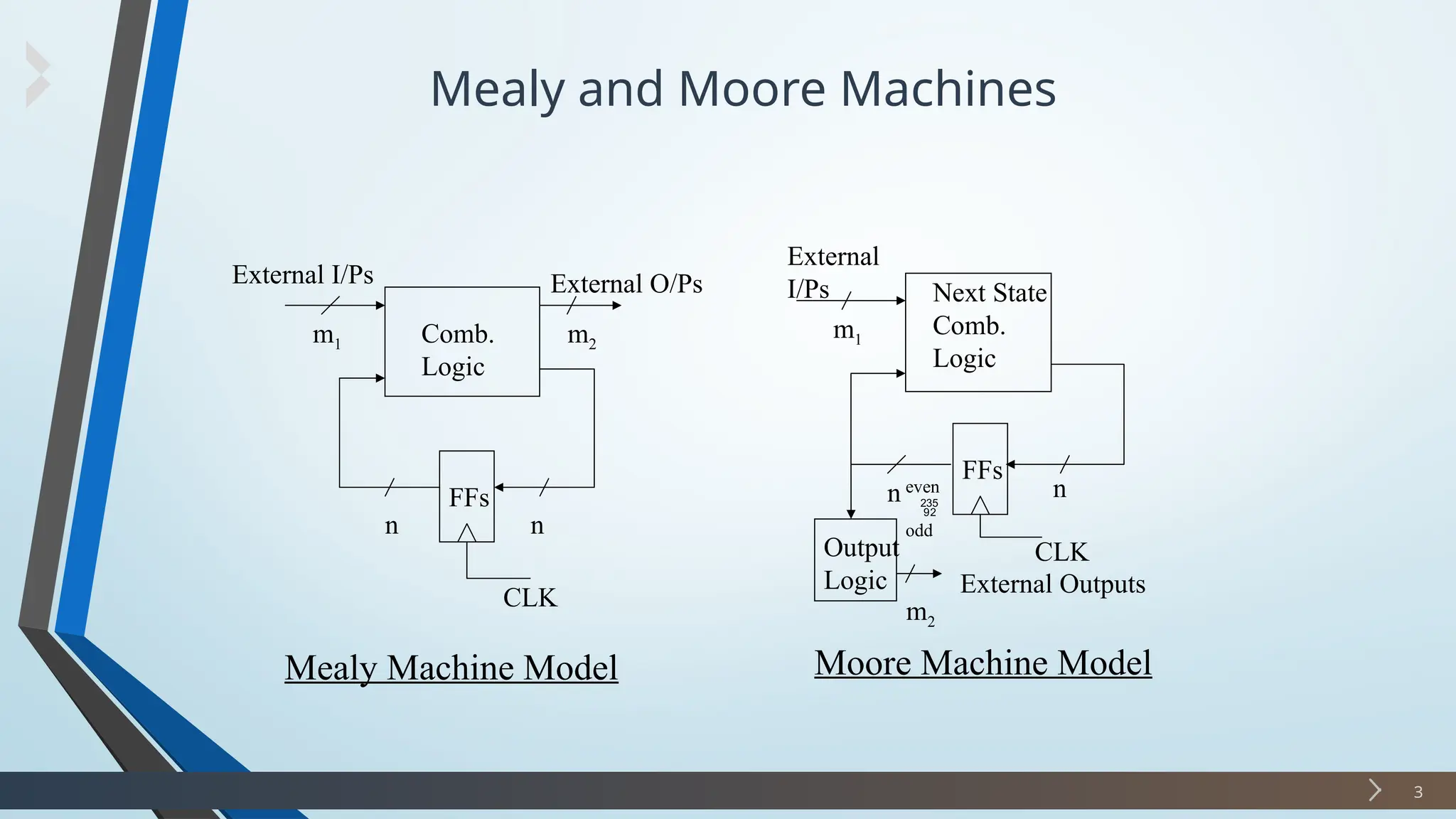
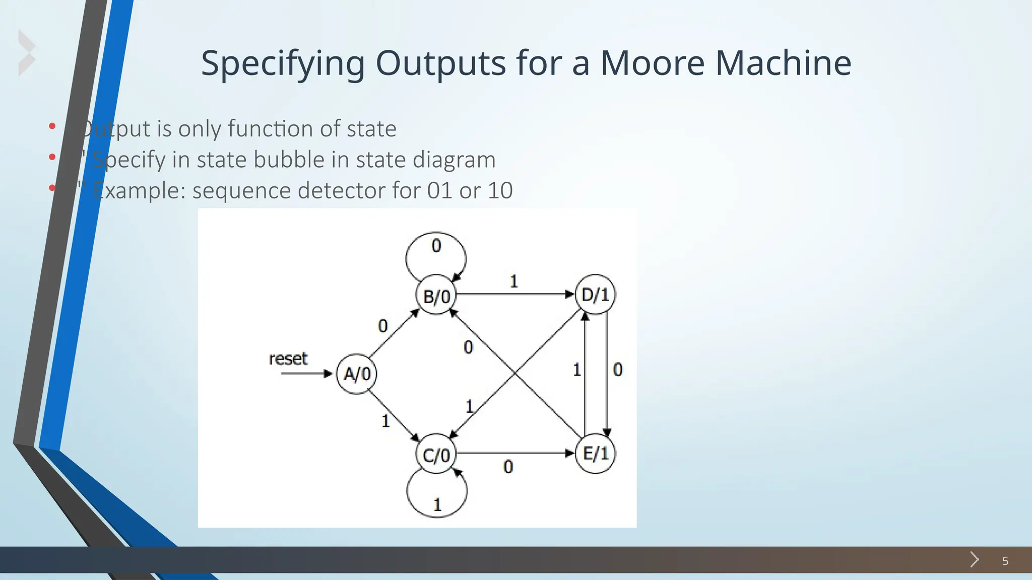
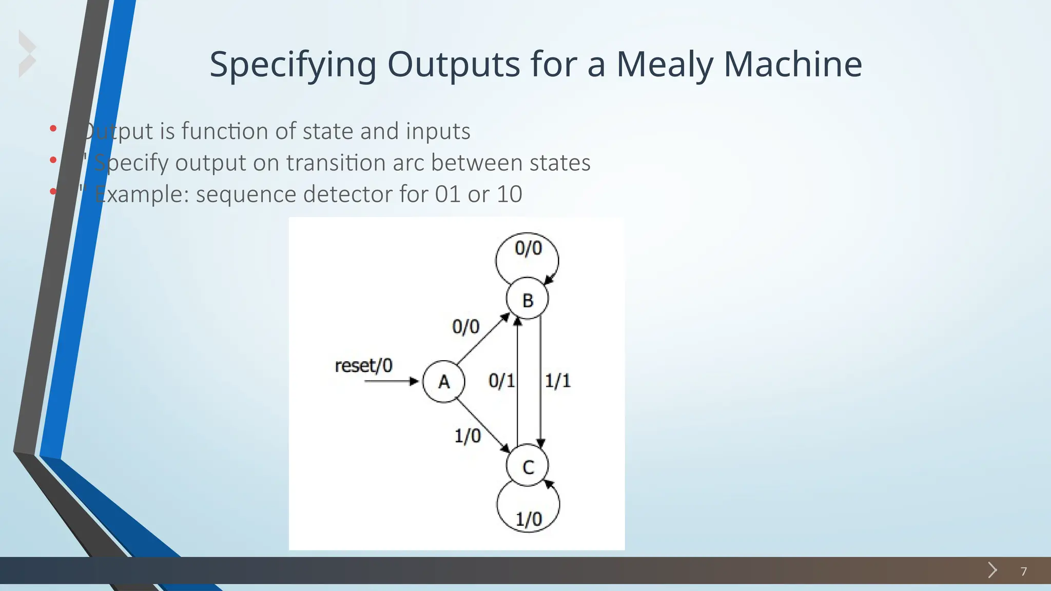
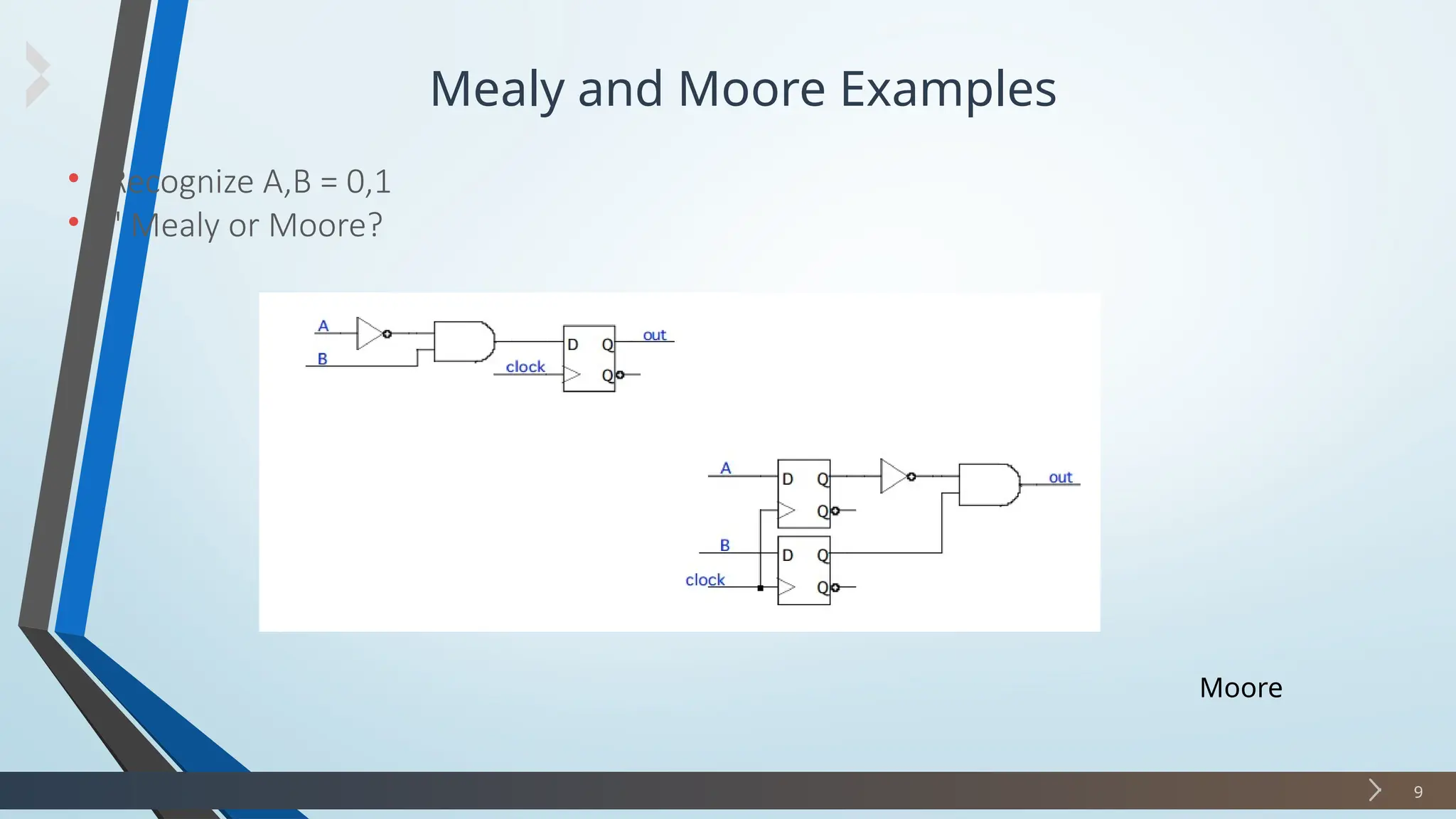
Digital Electronics
Finite State Machine
2
 FSMs are different from counters in the sense that they have external I/Ps, and state
transitions are dependent on these I/Ps and the current state.
 Simple forms of pattern matching.
 Models for sequential logic circuits, of the kind on which every present-day computer
and many device controllers is based.
Mealy and Moore Machines
3
FFs
External I/Ps External O/Ps
m1 m2
n
n
Comb.
Logic
CLK
FFs
n
CLK
n
Output
Logic
m2
Next State
Comb.
Logic
m1
External
I/Ps
External Outputs
Mealy Machine Model Moore Machine Model
even

odd
Difference Between Mealy and Moore Machine
4
Mealy Moore
(1) O/Ps depend on the present O/Ps depend only on the
state and present I/Ps present state
(2) The O/P change asyn Since the O/Ps change
-chronously with the when the state changes,
enabling clock edge and the state change is
synchronous with the
enabling clock edge, O/Ps
change synchronously
with this clock edge
(3) A counter is not a Mealy A counter is a Moore
machine machine
(4) A Mealy machine will have
the same # or fewer states
than a Moore machine
Specifying Outputs for a Moore Machine
5
• Output is only function of state
• " Specify in state bubble in state diagram
• " Example: sequence detector for 01 or 10
Specifying Outputs for a Moore Machine
6
Specifying Outputs for a Mealy Machine
7
• Output is function of state and inputs
• " Specify output on transition arc between states
• " Example: sequence detector for 01 or 10
Specifying Outputs for a Mealy Machine
8
Mealy and Moore Examples
9
• Recognize A,B = 0,1
• " Mealy or Moore?
Moore
Mealy and Moore Examples
10
• Recognize A,B = 0,1
• " Mealy or Moore?
Mealy
Questions 01
11
• Design a simple sequence detector for the sequence 011 (using Moore)
1. Construct its state output table.
2. Assign the state assignment based on binary, gray code and one hot method.
3. Construct the state excitation table by using D – Flip Flop and gray code state
assignment.
4. Write and simplify the state equations and output equations
5. Draw a circuit diagram
Questions 01
12

10 Mealy and Moore model in discrete maths

  • 1.
  • 2.
    Finite State Machine 2 FSMs are different from counters in the sense that they have external I/Ps, and state transitions are dependent on these I/Ps and the current state.  Simple forms of pattern matching.  Models for sequential logic circuits, of the kind on which every present-day computer and many device controllers is based.
  • 3.
    Mealy and MooreMachines 3 FFs External I/Ps External O/Ps m1 m2 n n Comb. Logic CLK FFs n CLK n Output Logic m2 Next State Comb. Logic m1 External I/Ps External Outputs Mealy Machine Model Moore Machine Model even  odd
  • 4.
    Difference Between Mealyand Moore Machine 4 Mealy Moore (1) O/Ps depend on the present O/Ps depend only on the state and present I/Ps present state (2) The O/P change asyn Since the O/Ps change -chronously with the when the state changes, enabling clock edge and the state change is synchronous with the enabling clock edge, O/Ps change synchronously with this clock edge (3) A counter is not a Mealy A counter is a Moore machine machine (4) A Mealy machine will have the same # or fewer states than a Moore machine
  • 5.
    Specifying Outputs fora Moore Machine 5 • Output is only function of state • " Specify in state bubble in state diagram • " Example: sequence detector for 01 or 10
  • 6.
    Specifying Outputs fora Moore Machine 6
  • 7.
    Specifying Outputs fora Mealy Machine 7 • Output is function of state and inputs • " Specify output on transition arc between states • " Example: sequence detector for 01 or 10
  • 8.
    Specifying Outputs fora Mealy Machine 8
  • 9.
    Mealy and MooreExamples 9 • Recognize A,B = 0,1 • " Mealy or Moore? Moore
  • 10.
    Mealy and MooreExamples 10 • Recognize A,B = 0,1 • " Mealy or Moore? Mealy
  • 11.
    Questions 01 11 • Designa simple sequence detector for the sequence 011 (using Moore) 1. Construct its state output table. 2. Assign the state assignment based on binary, gray code and one hot method. 3. Construct the state excitation table by using D – Flip Flop and gray code state assignment. 4. Write and simplify the state equations and output equations 5. Draw a circuit diagram
  • 12.