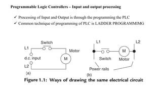
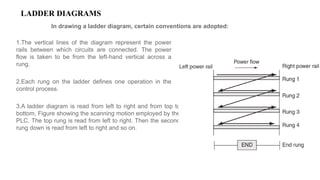
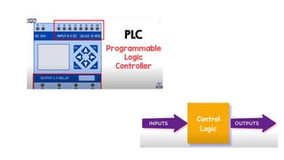
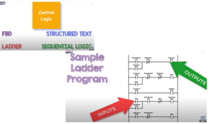
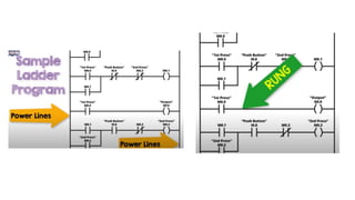
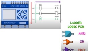
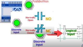
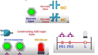
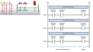
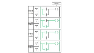
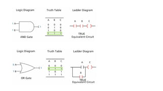
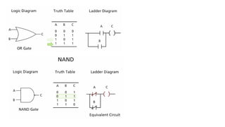
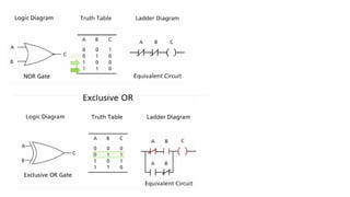
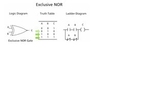
ME-8791 Mechatronics
UNIT-IV Programmable Logic Controller
Dr.S.Ganeshkumar
Asst. Prof/Mechanical Engg
SECE/MECHANICAL
UNIT IV PROGRAMMABLE LOGIC CONTROLLER
Introduction – Basic structure – Input and output processing – Programming –
Mnemonics – Timers, counters and internal relays – Data handling – Selection of
PLC
Unit - 4
Basic Structure of PLC
Opt isolator
An opto-isolator is an electronic component that transfers electrical signals between two
isolated circuits by using light. Opto-isolators prevent high voltages from affecting the
system receiving the signal.
Application of PLC
Programmable Logic Controllers – Input and output processing
 Processing of Input and Output is through the programming the PLC
 Common technique of programming of PLC is LADDER PROGRAMMIMG
LADDER DIAGRAMS
In drawing a ladder diagram, certain conventions are adopted:
1.The vertical lines of the diagram represent the power
rails between which circuits are connected. The power
flow is taken to be from the left-hand vertical across a
rung.
2.Each rung on the ladder defines one operation in the
control process.
3.A ladder diagram is read from left to right and from top to
bottom, Figure showing the scanning motion employed by the
PLC. The top rung is read from left to right. Then the second
rung down is read from left to right and so on.
LADDER DIAGRAMS
In drawing a ladder diagram, certain conventions are adopted:
4.Each rung must start with an input or inputs and must
end with at least one output. The term input is used for a
control action, such as closing the contacts of a switch,
used as an input to the PLC. The term output is used for a
device connected to the output of a PLC, e.g., a motor.
5.Electrical devices are shown in their normal condition.
Thus a switch, which is normally open until some object
closes it, is shown as open on the ladder diagram. A
switch that is normally closed is shown closed.
6.A particular device can appear in more than one rung of
a ladder. For example, we might have a relay that
switches on one or more devices. The same letters and/or
numbers are used to label the device in each situation.
LADDER DIAGRAMS
In drawing a ladder diagram, certain conventions are adopted:
7.The inputs and outputs are all identified by their
addresses, the notation used depending on the PLC
manufacturer. This is the address of the input or output in
the memory of the PLC.
LADDER DIAGRAMS
In drawing a ladder diagram, certain conventions are adopted:
7.The inputs and outputs are all identified by their
addresses, the notation used depending on the PLC
manufacturer. This is the address of the input or output in
the memory of the PLC.
Mechatronics  Programmable Logic Controllers

Mechatronics Programmable Logic Controllers

  • 1.
    ME-8791 Mechatronics UNIT-IV ProgrammableLogic Controller Dr.S.Ganeshkumar Asst. Prof/Mechanical Engg SECE/MECHANICAL
  • 2.
    UNIT IV PROGRAMMABLELOGIC CONTROLLER Introduction – Basic structure – Input and output processing – Programming – Mnemonics – Timers, counters and internal relays – Data handling – Selection of PLC
  • 3.
  • 4.
  • 5.
    Opt isolator An opto-isolatoris an electronic component that transfers electrical signals between two isolated circuits by using light. Opto-isolators prevent high voltages from affecting the system receiving the signal.
  • 6.
  • 7.
    Programmable Logic Controllers– Input and output processing  Processing of Input and Output is through the programming the PLC  Common technique of programming of PLC is LADDER PROGRAMMIMG
  • 8.
    LADDER DIAGRAMS In drawinga ladder diagram, certain conventions are adopted: 1.The vertical lines of the diagram represent the power rails between which circuits are connected. The power flow is taken to be from the left-hand vertical across a rung. 2.Each rung on the ladder defines one operation in the control process. 3.A ladder diagram is read from left to right and from top to bottom, Figure showing the scanning motion employed by the PLC. The top rung is read from left to right. Then the second rung down is read from left to right and so on.
  • 9.
    LADDER DIAGRAMS In drawinga ladder diagram, certain conventions are adopted: 4.Each rung must start with an input or inputs and must end with at least one output. The term input is used for a control action, such as closing the contacts of a switch, used as an input to the PLC. The term output is used for a device connected to the output of a PLC, e.g., a motor. 5.Electrical devices are shown in their normal condition. Thus a switch, which is normally open until some object closes it, is shown as open on the ladder diagram. A switch that is normally closed is shown closed. 6.A particular device can appear in more than one rung of a ladder. For example, we might have a relay that switches on one or more devices. The same letters and/or numbers are used to label the device in each situation.
  • 10.
    LADDER DIAGRAMS In drawinga ladder diagram, certain conventions are adopted: 7.The inputs and outputs are all identified by their addresses, the notation used depending on the PLC manufacturer. This is the address of the input or output in the memory of the PLC.
  • 11.
    LADDER DIAGRAMS In drawinga ladder diagram, certain conventions are adopted: 7.The inputs and outputs are all identified by their addresses, the notation used depending on the PLC manufacturer. This is the address of the input or output in the memory of the PLC.