The document discusses the basic structure and programming of programmable logic controllers (PLCs). It contains the following key points:
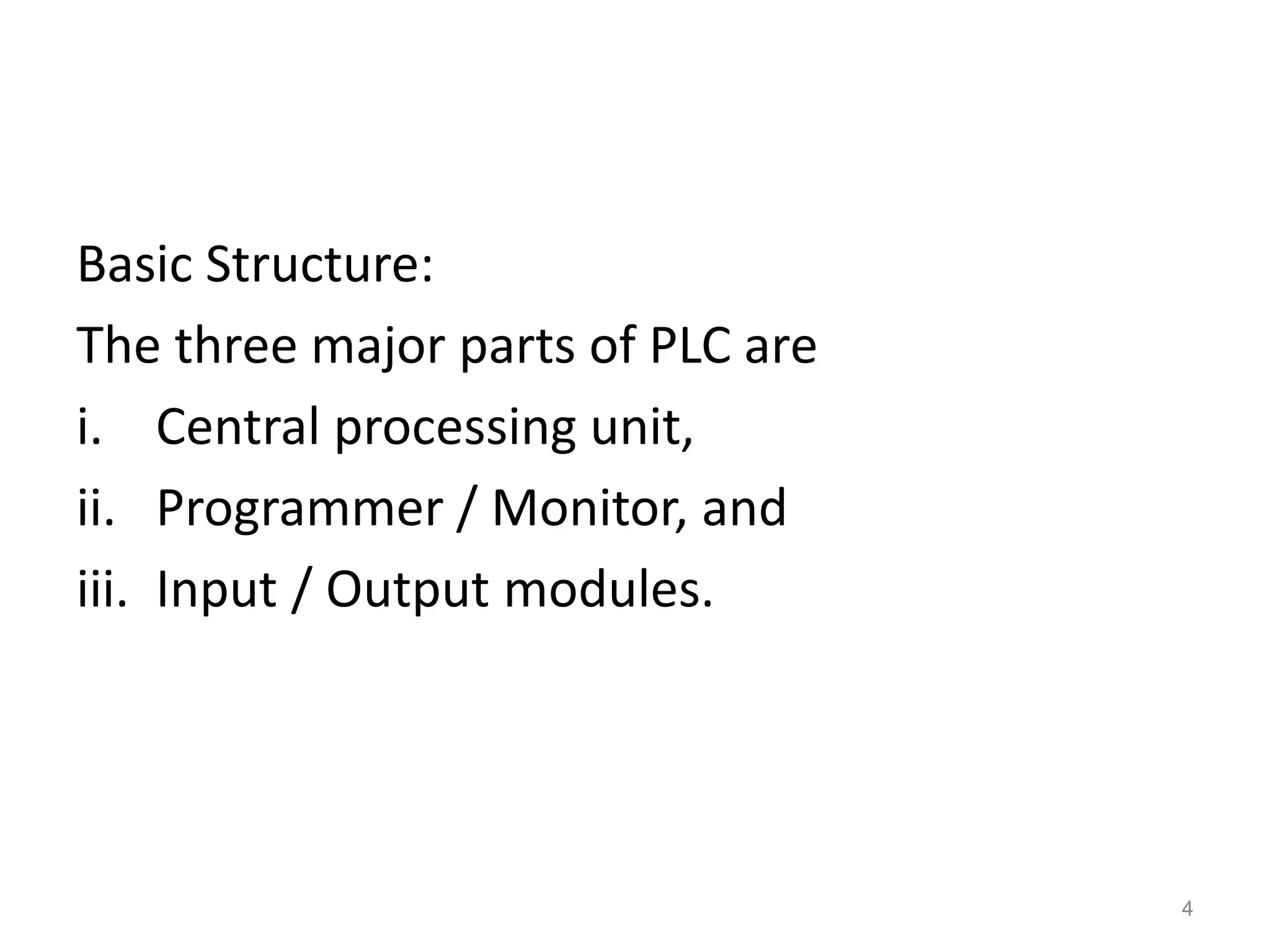
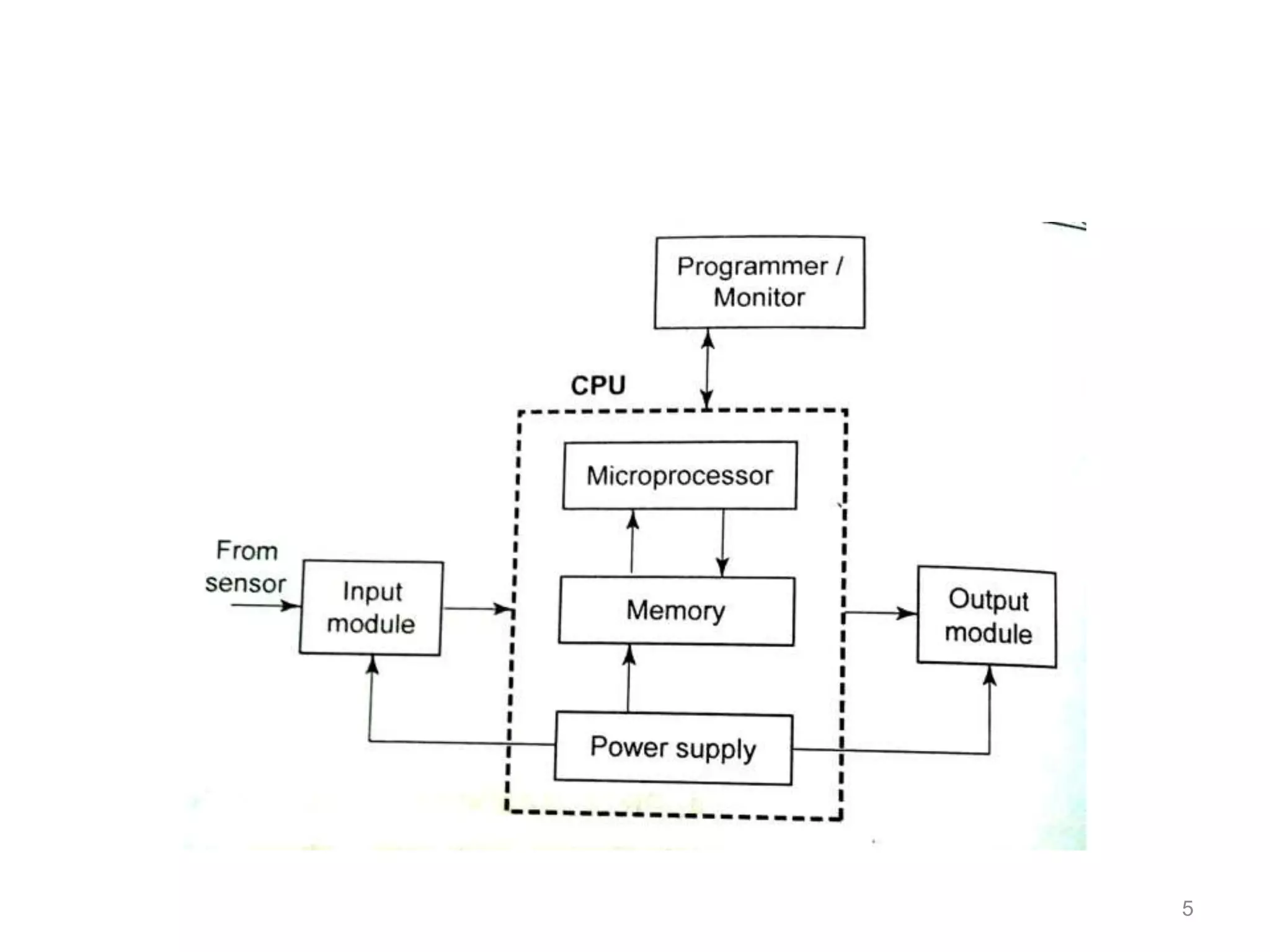
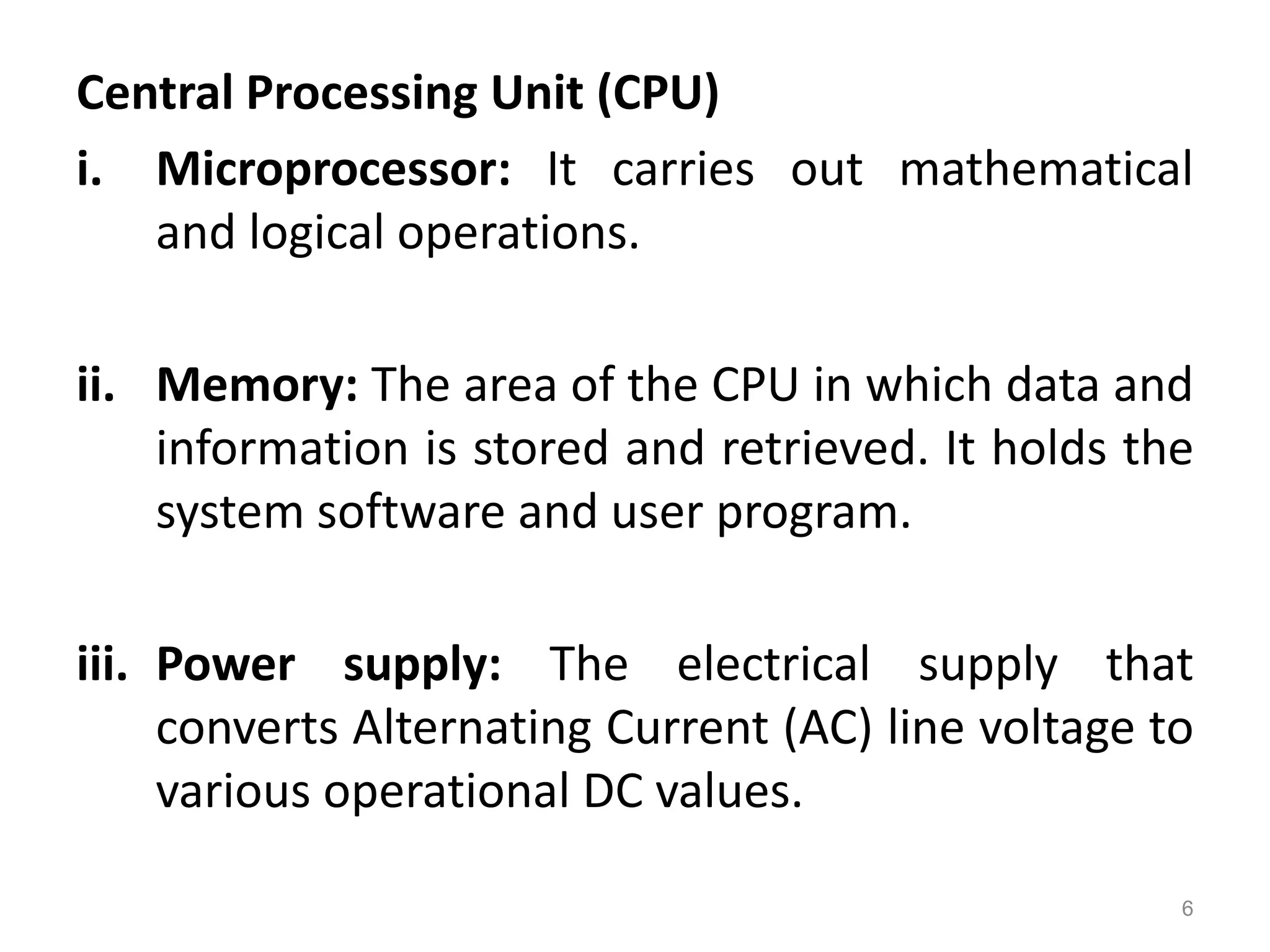
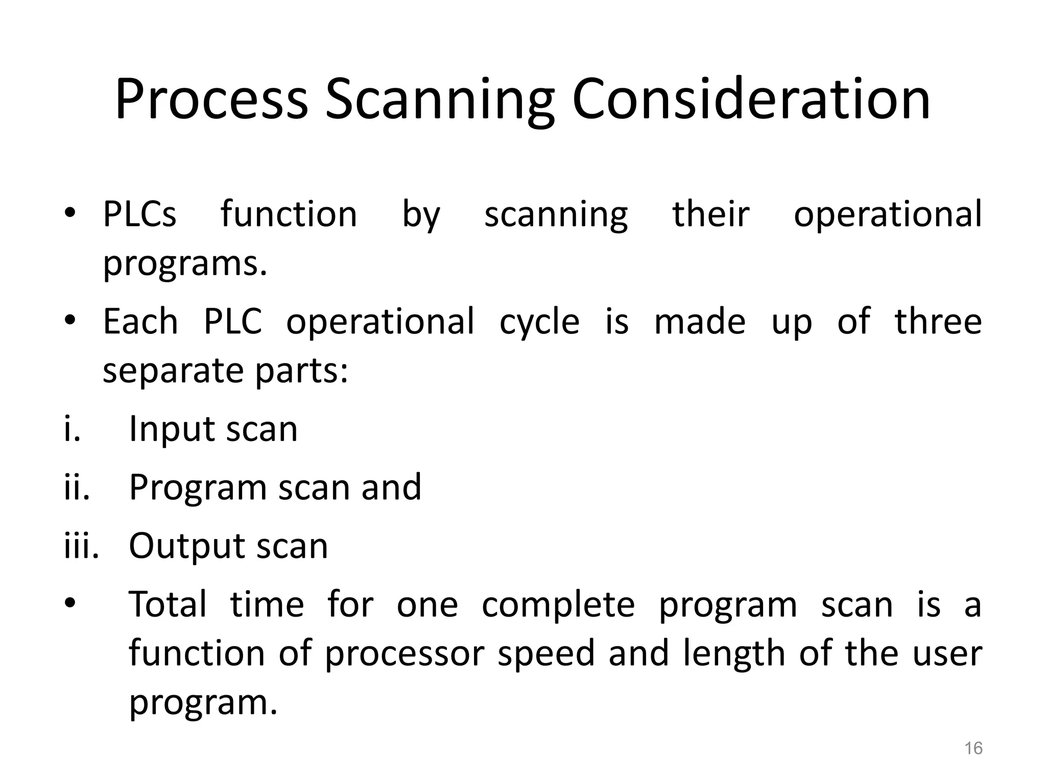
1. A PLC has three main parts: a central processing unit, programmer/monitor, and input/output modules. The CPU performs logical and mathematical operations using a microprocessor and memory.
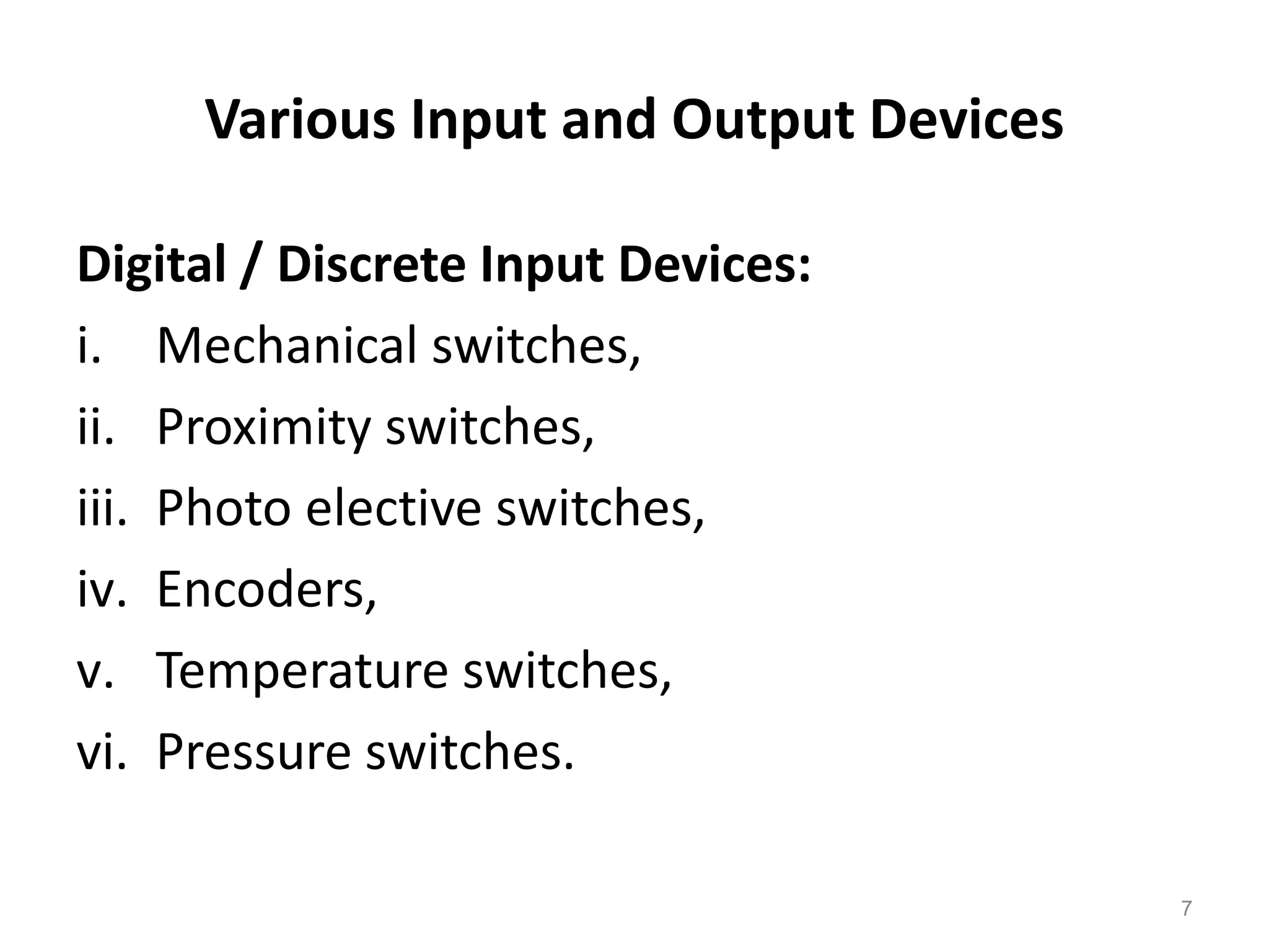
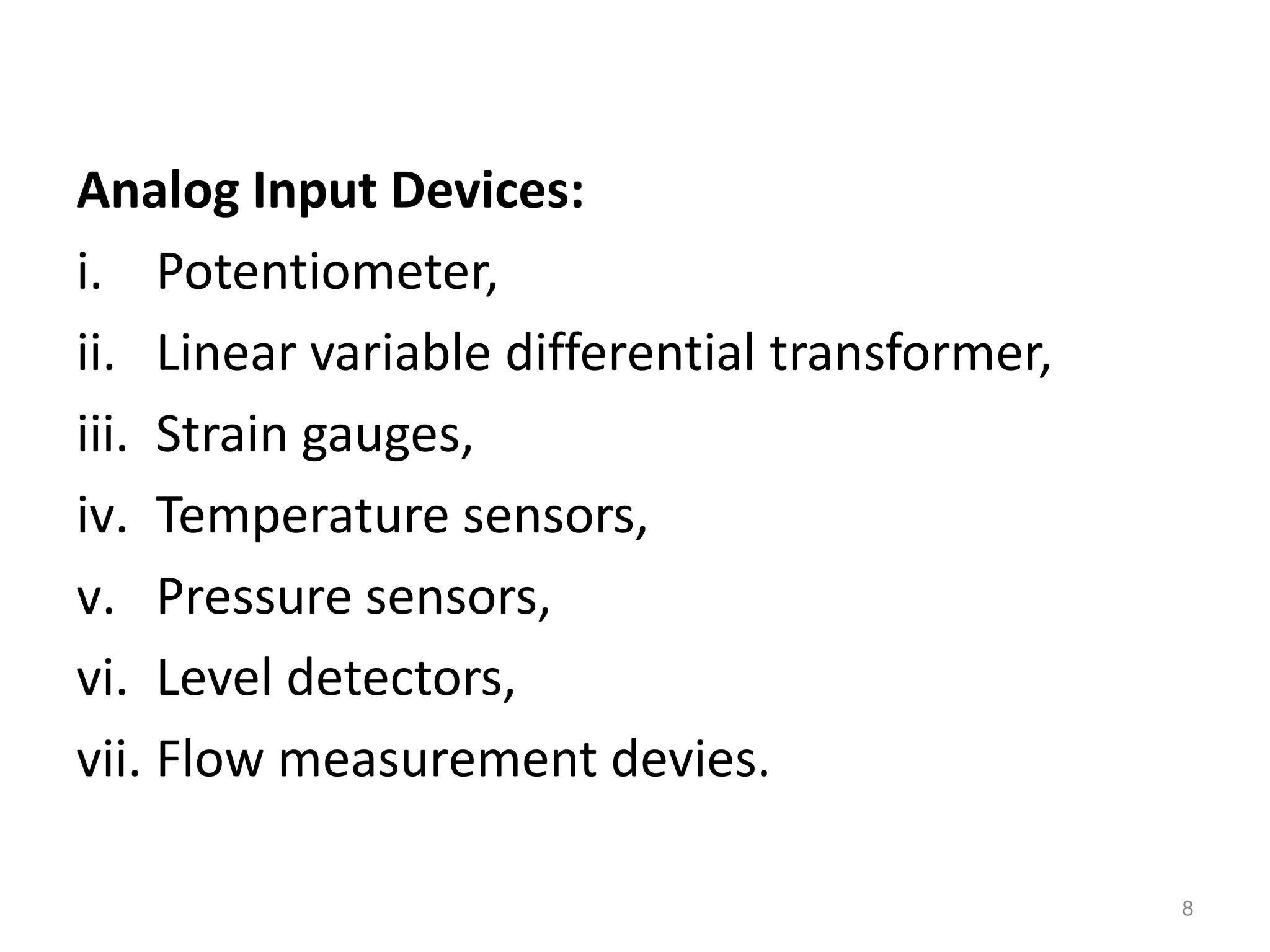
2. PLCs are used in industrial environments to control machines and processes. They accept digital and analog inputs from sensors and switches, and provide outputs to devices like motors and valves.
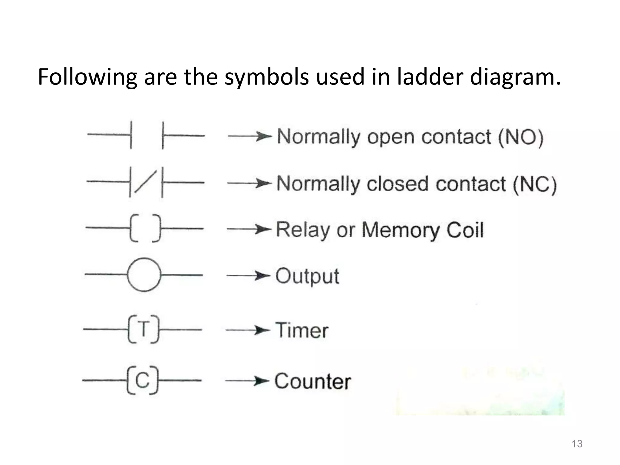
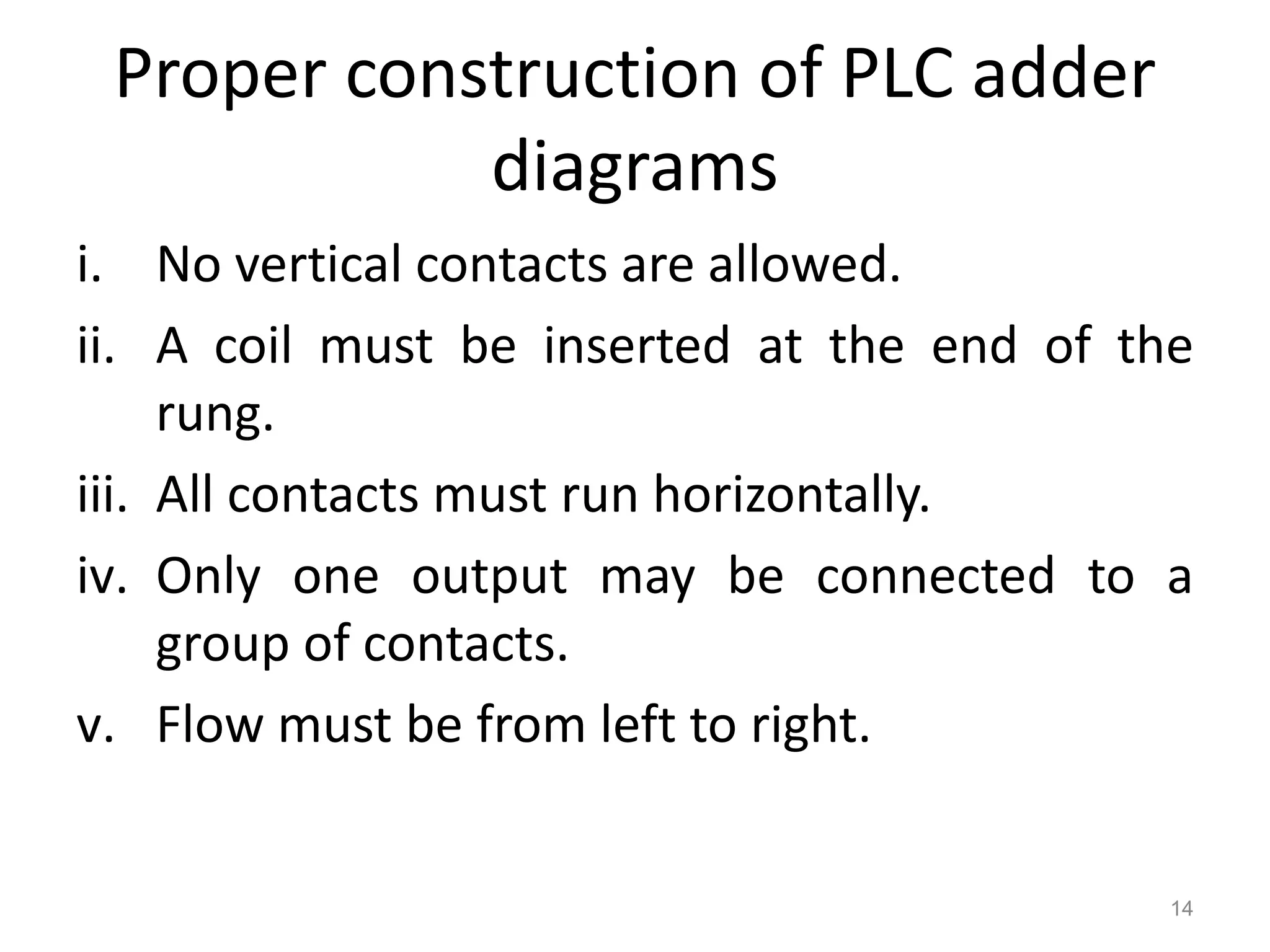
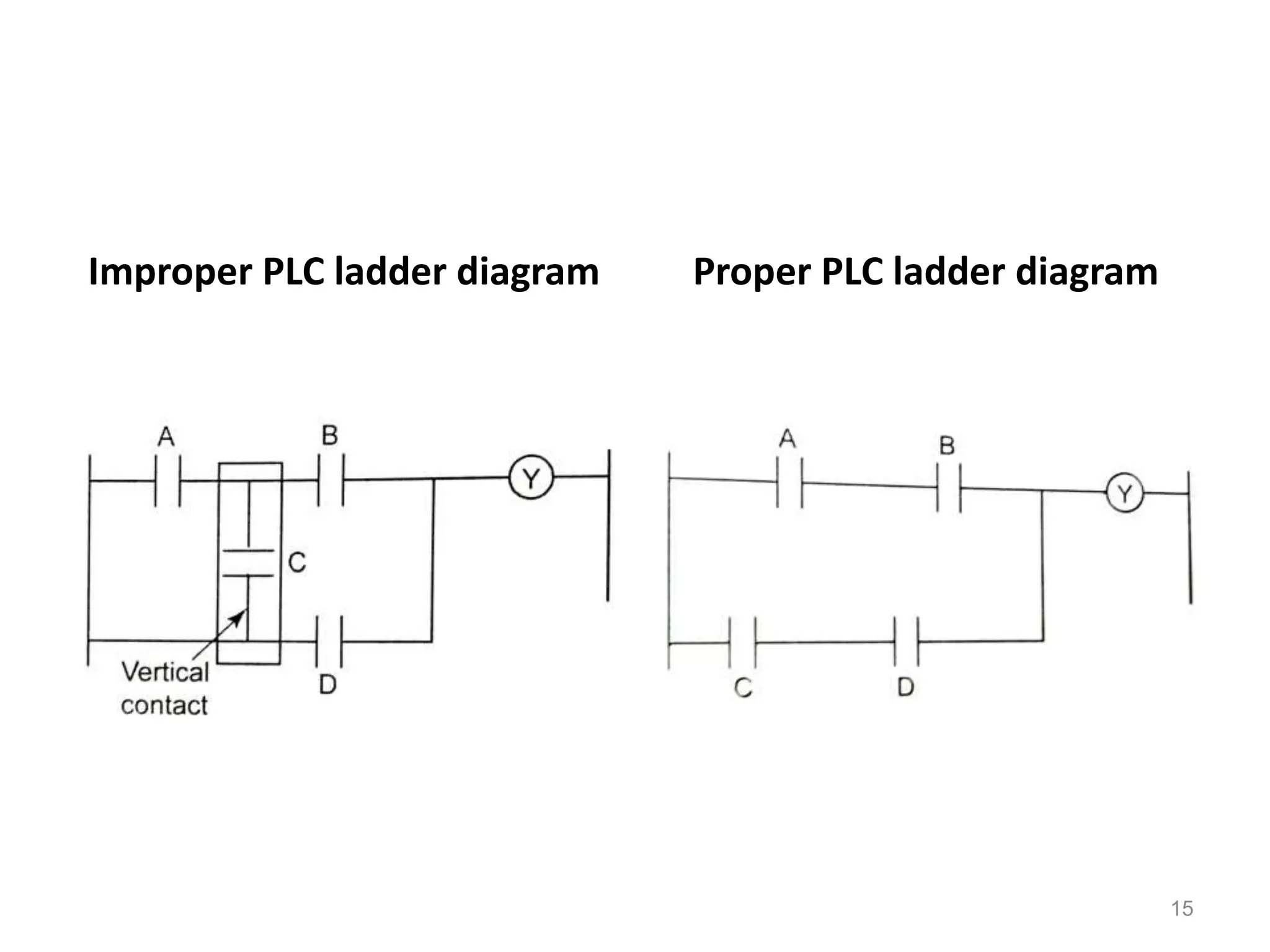
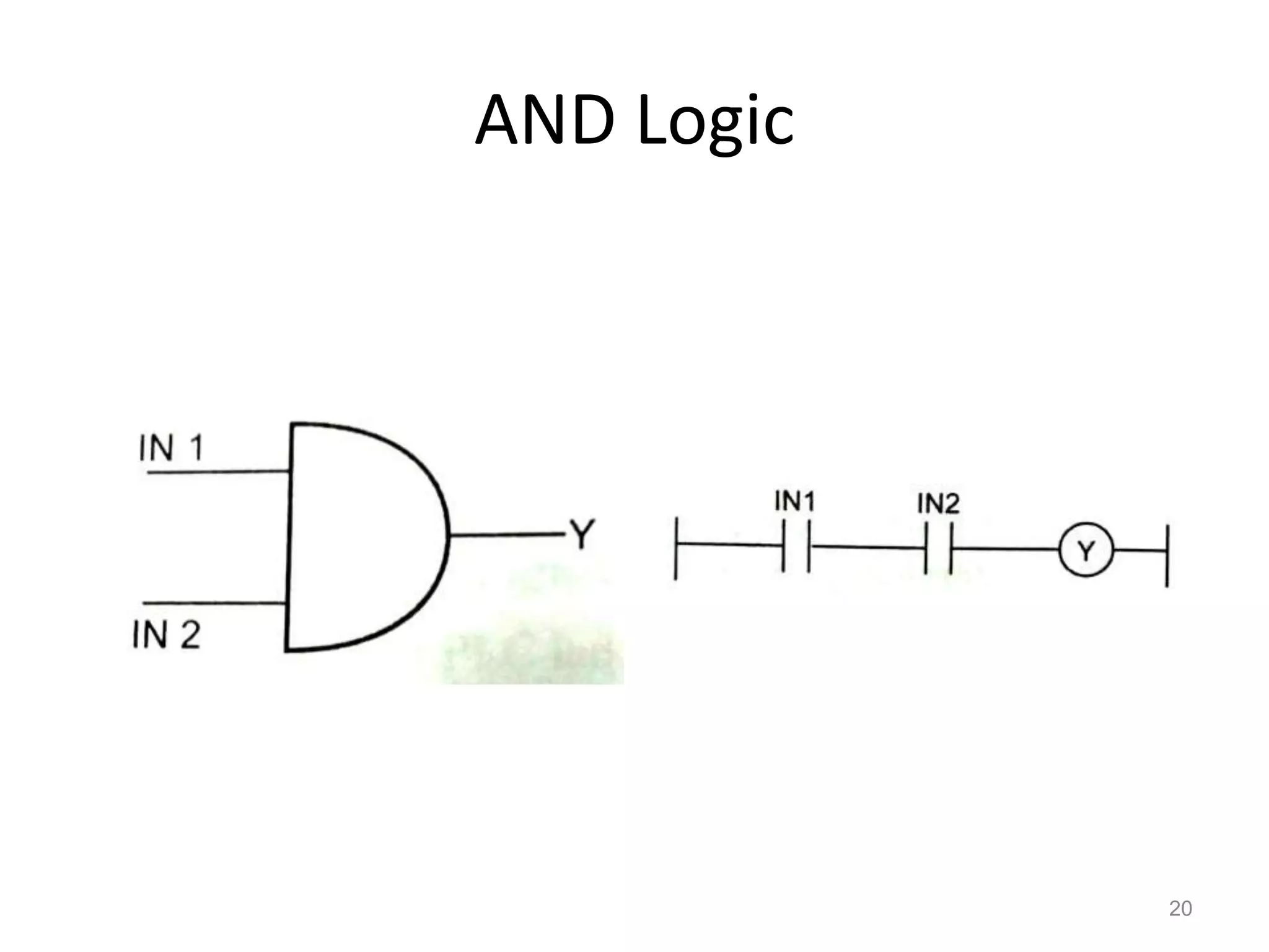
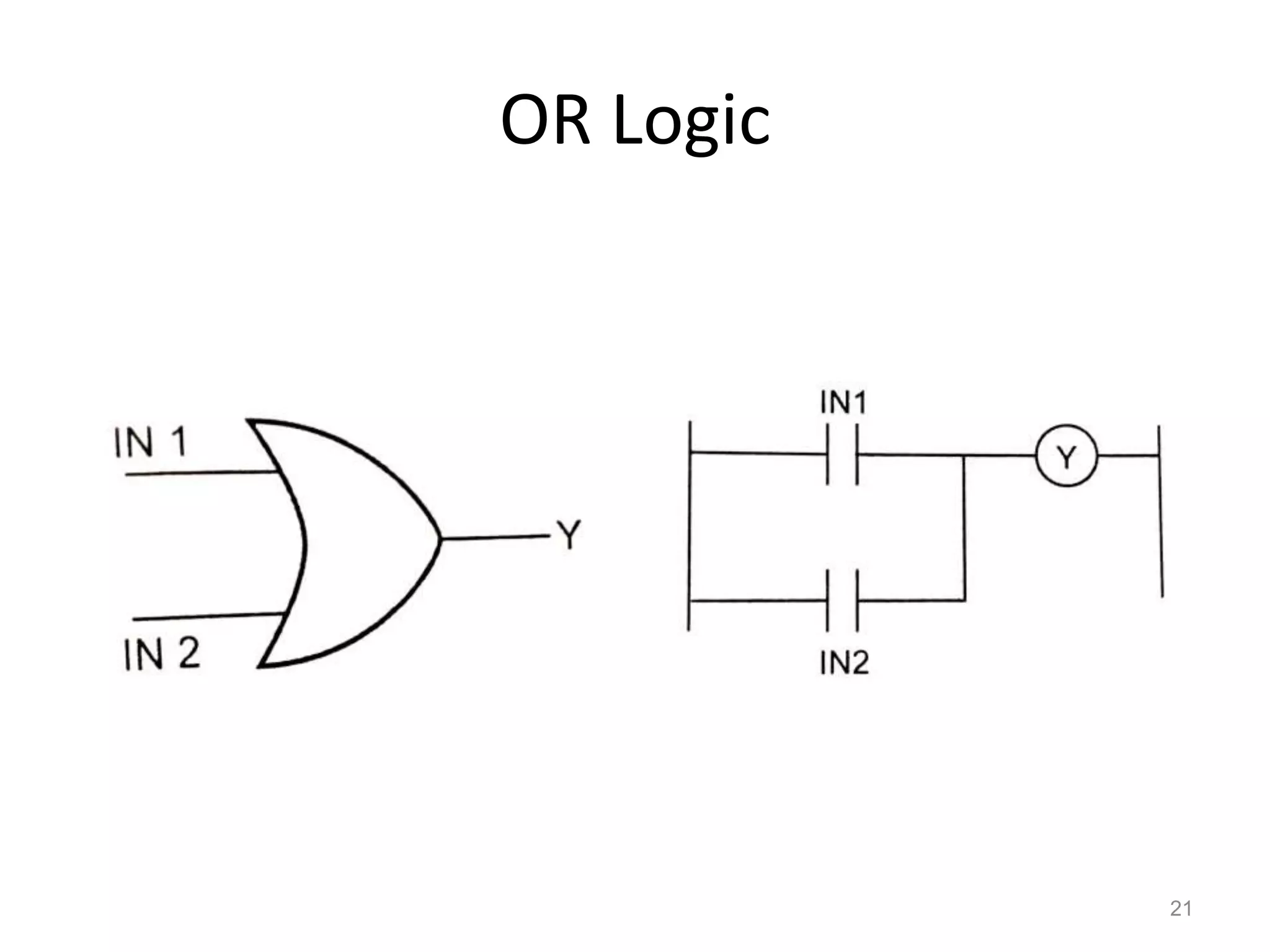
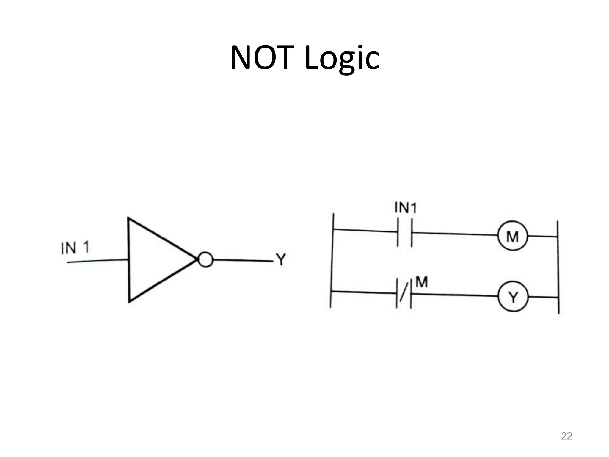
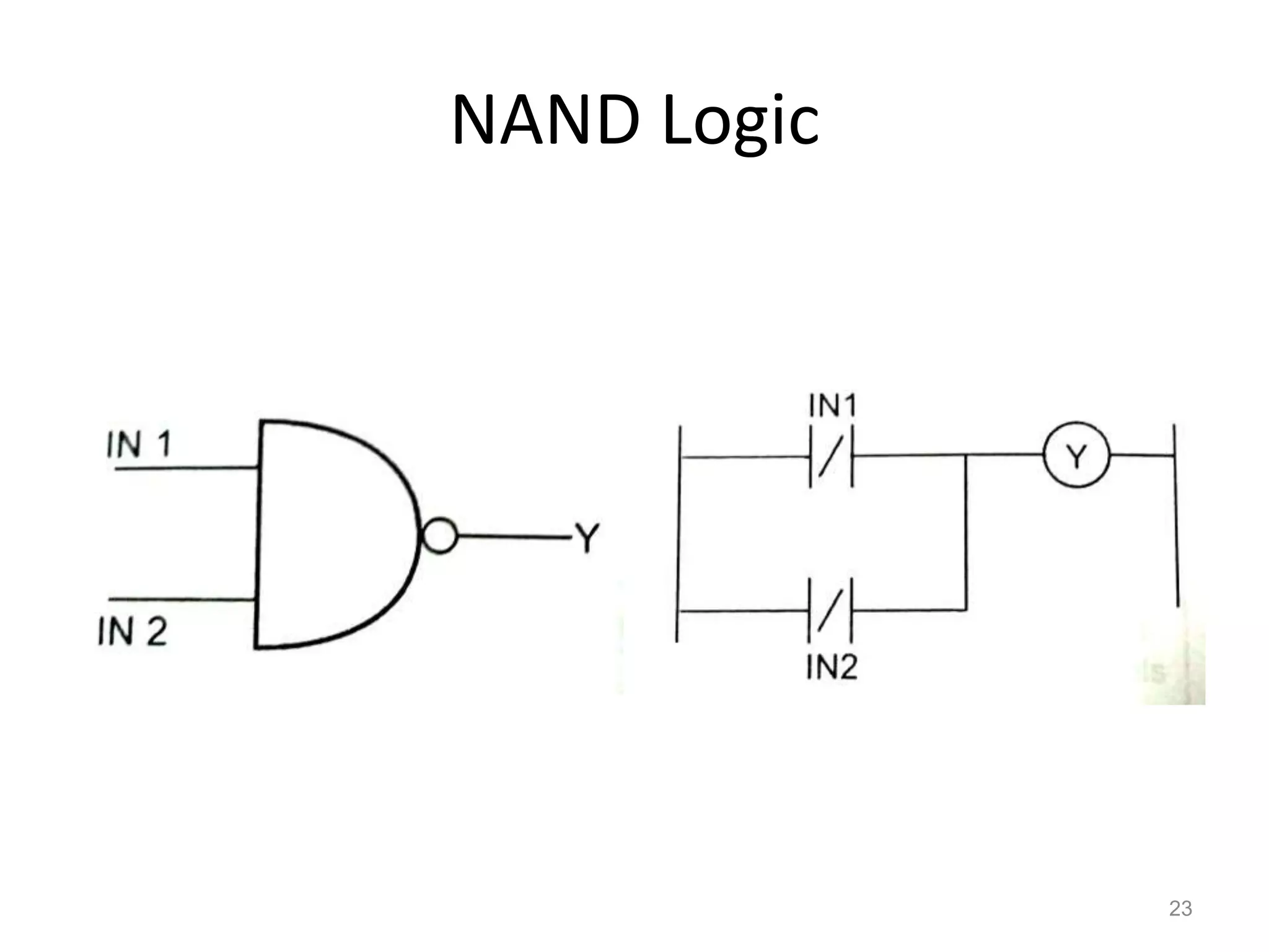
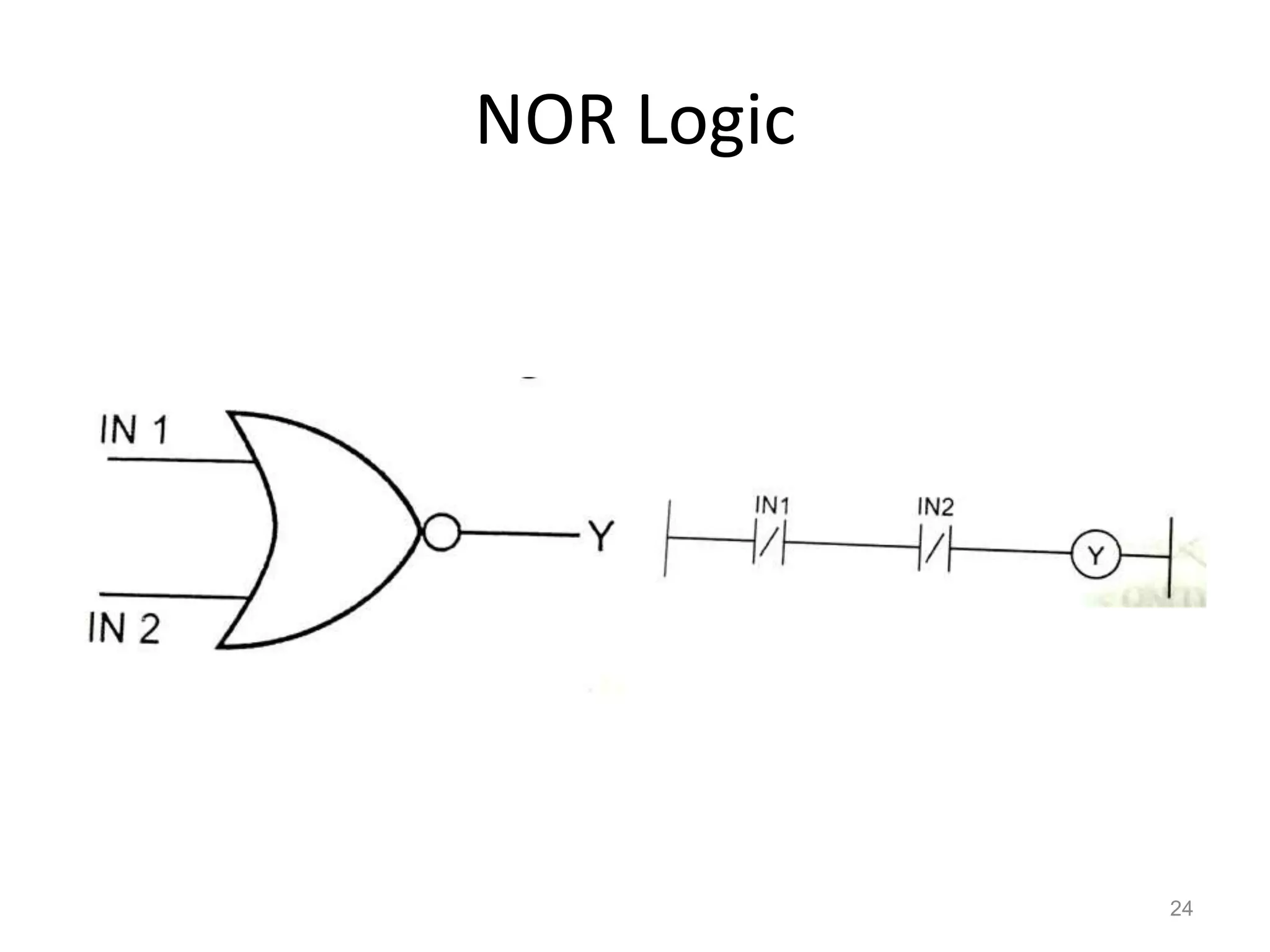
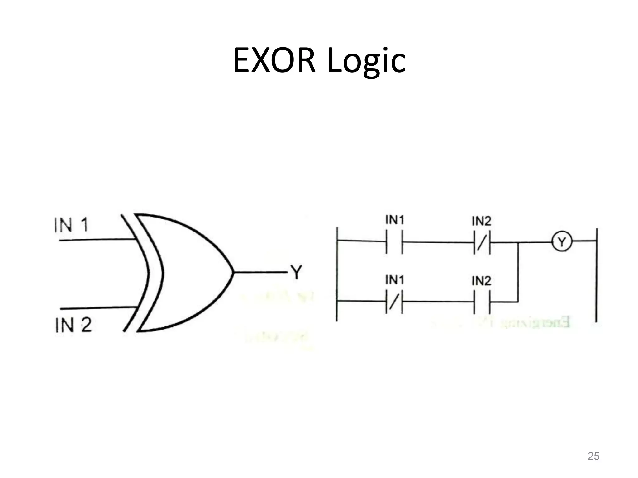
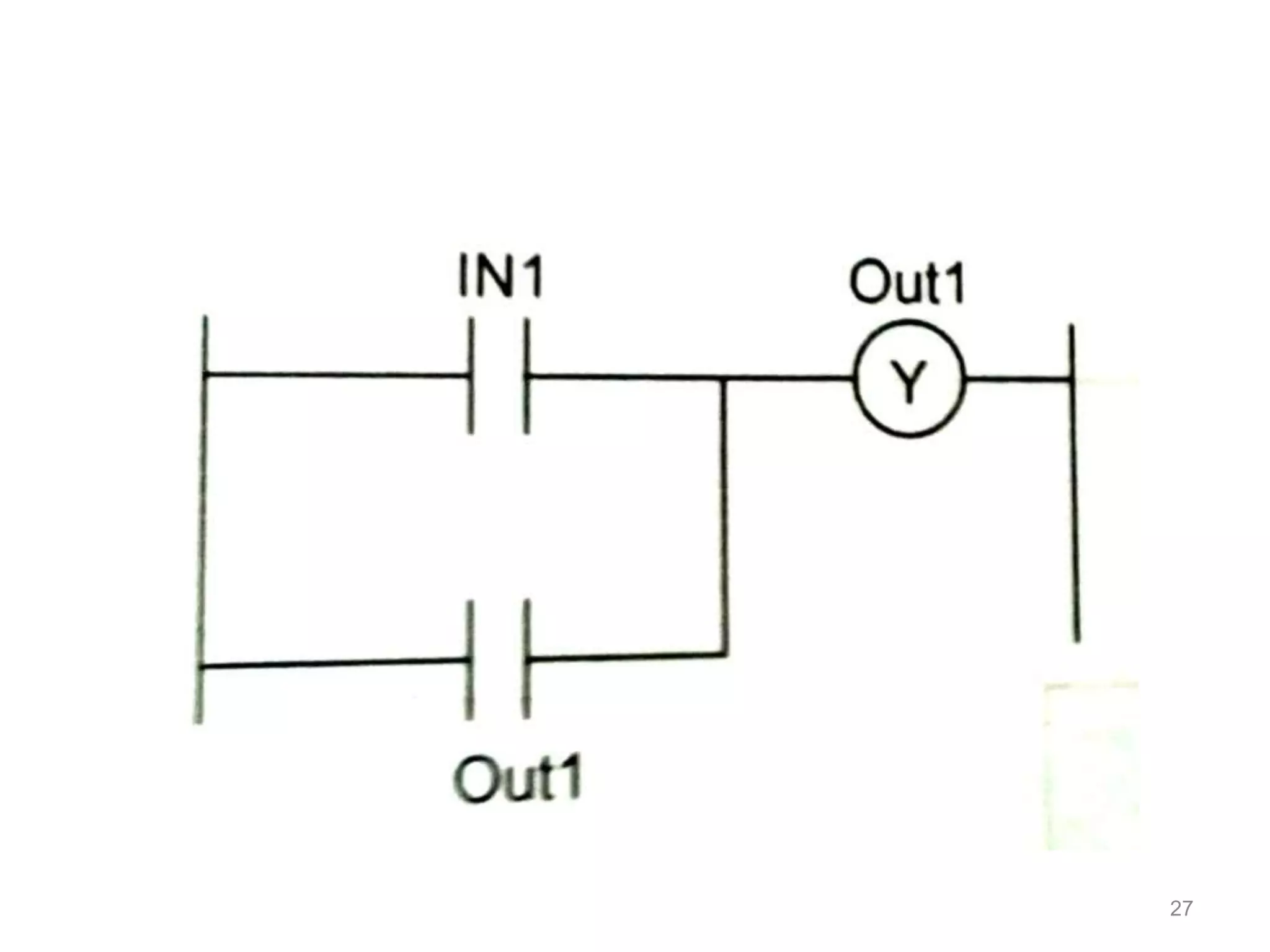
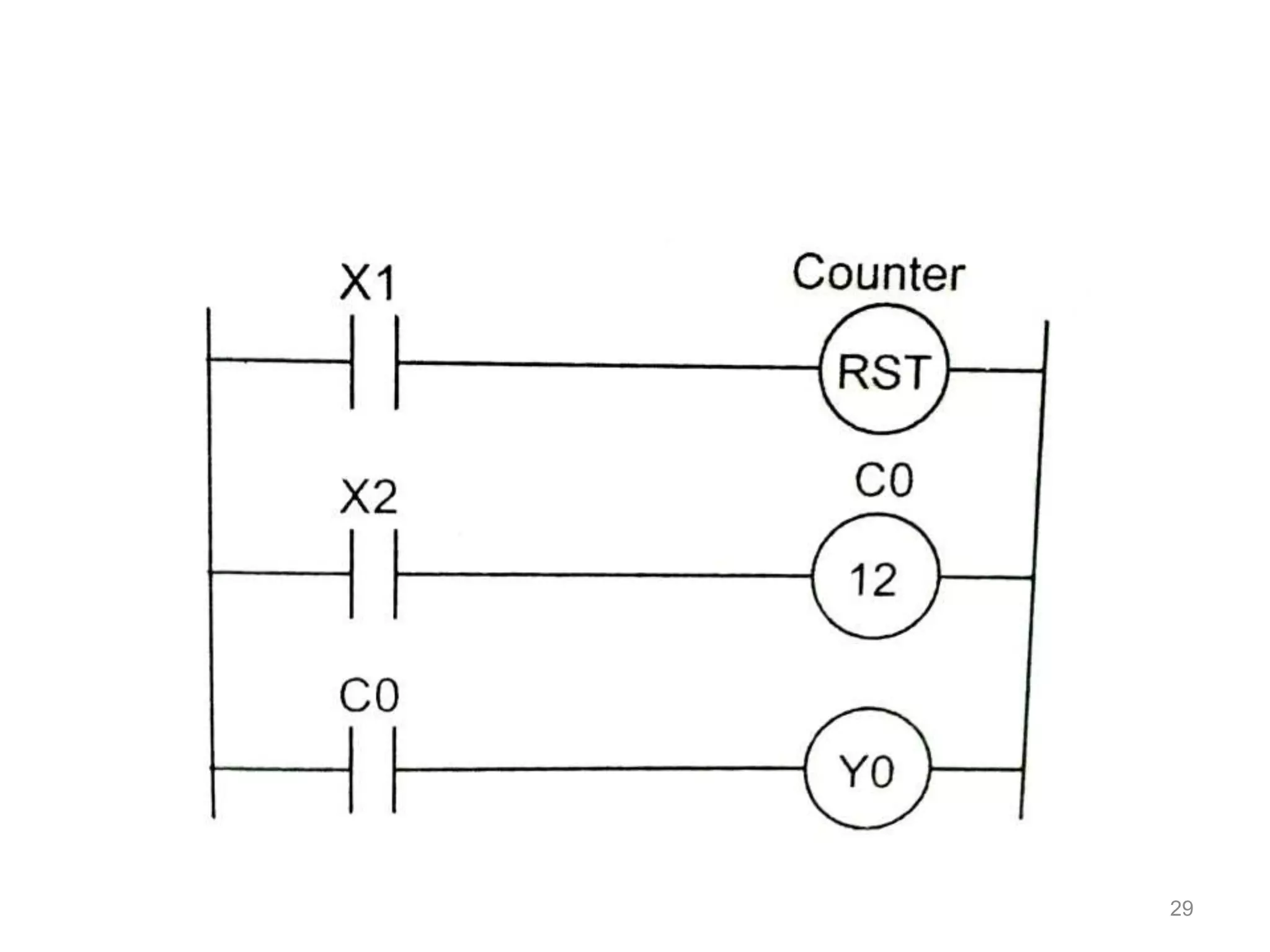
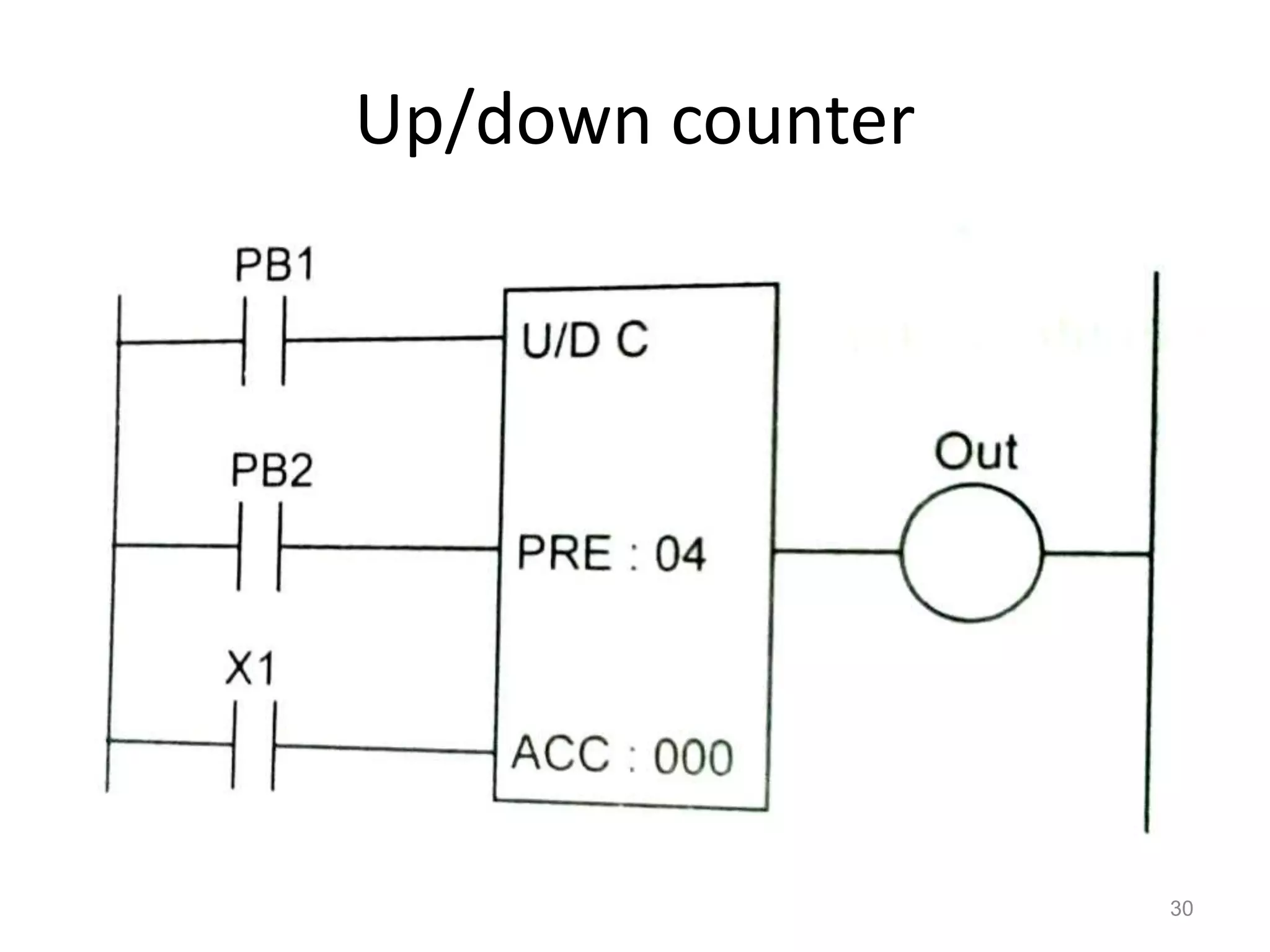
3. PLC programming is usually done using ladder logic, which resembles electrical circuit diagrams. Proper ladder diagrams follow rules like having contacts run horizontally and coils at the end of rungs.


![I-_UNIT-_CURVES [Autosaved].pptx](https://cdn.slidesharecdn.com/ss_thumbnails/i-unit-curvesautosaved-220821135918-dd2d85a0-thumbnail.jpg?width=640&height=640&fit=bounds)


