This document discusses the design of a machining fixture for a support bracket used in a vertical turning center, aiming to improve productivity by reducing operation costs and time. The project highlights the design process, materials used, and various calculations for machining operations, indicating a significant increase in production efficiency and reduced labor costs. Additionally, it includes a literature review emphasizing advancements in fixture design and requirements based on customer specifications.
![ISSN 2393-8471
International Journal of Recent Research in Civil and Mechanical Engineering (IJRRCME)
Vol. 3, Issue 1, pp: (1-9), Month: April 2016 – September 2016, Available at: www.paperpublications.org
Page | 2
Paper Publications
tool. Any average person can be trained to use Jigs & Fixtures. The replacement of a skilled workman with unskilled labor
can effect substantial saving in labor cost.
d) Cost Reduction: Higher production, reduction in scrap, easy assembly and savings in labor costs results in substantial
reduction in the cost of work pieces produced with Jigs & Fixtures.
1.3 Material used:
Jigs and fixtures are made from a variety of materials some of them can be hardened to resist wear. It is sometimes
necessary to use non-ferrous metals like Phosphor Bronze or Brass to reduce wear of mating parts or Nylons or Fiber to
prevent damage to the work piece.
Mild steel: It is the cheapest and most widely used material in Jigs & Fixtures. It contains less than 0.3%C. Steel En 2
falls in this category. This steel can be case hardened to 56 HRC. It is used to make parts which are not subjected to wear
and not highly stressed. .
High Tensile Steels: These can be classified into medium carbon steels with 0.45-0.65%C (En 8, En 9) and alloy steels
like En 24 (40Ni2Cr1Mo28).The tensile strength can be increased up to 125 kg/mm2 by tempering.
Case Hardening Steels: These can be carburized and case hardened to provide 0.6-1.5 mm thick, hard exterior (58-62
HRC). 17Mn1Cr95 steels with 1%Mn and 0.95%Cr is widely used for locating pins, Rest pads etc. These steels are
suitable for parts which require only local hardness on small wearing surfaces.(Ex: En 353, En 36).
Cast Iron: It contains 2-2.5%C. As it can withstand vibrations well, it is used widely in milling fixtures. The ingenious
shaping of a casting and the pattern can save a lot of machining time. Nodular CI is as strong as MS while Meehanite
castings have heat resistance, wear resistance and corrosion resistance grades.
Nylon and Fiber: These are usually used as soft lining of clamps to prevent denting or damage to work piece under high
clamping pressure. Nylon or Fiber pads are screwed or stuck to mild steel clamps.
2. LITERATURE REVIEW
A literature search is performed to understand the fixture-workpiece systems. Much research has been done regarding
fixture-workpiece systems. These studies give a great insight into various fixturing schemes. However, these studies lack
the focus on theturning process. N.P.Maniar and D.P.Vakhariya[1]
have introduced the proposes direction for future
research of fixture. In his paper Basic requirements of fixture, phases of fixture design, Dedicated and modular fixtures,
Flexible mechanical fixtures, locating and clamping consideration, Fixture design process and computer aided fixture
design have explained very well for the Design and Development of Fixture.R.D.Makwana and N.D.Gosvami[2]
have
study is about the 3-2-1 principle of fixture design and the different approaches which are used in the related fixture
design are explained. ShaileshS.Pachbhai and LaukikP.Raut[3]
details to minimizing workpiece deformation due to
clamping and cutting forces is essential to maintain the machining accuracy, different Steps of fixture design, study of
Elements of Fixtures and different types of locator and clamping Tom Zacharia and M.S. Steve [4]
The design
requirements of the fixture were studied and cutting forces were calculated. Strap clamp which is convenient to use the
fixture at different machine beds is designed and modeled. Fixture models were developed in 3D modeling softwares.
3. FIXTURE DESIGN FOR SUPPORT BRACKET
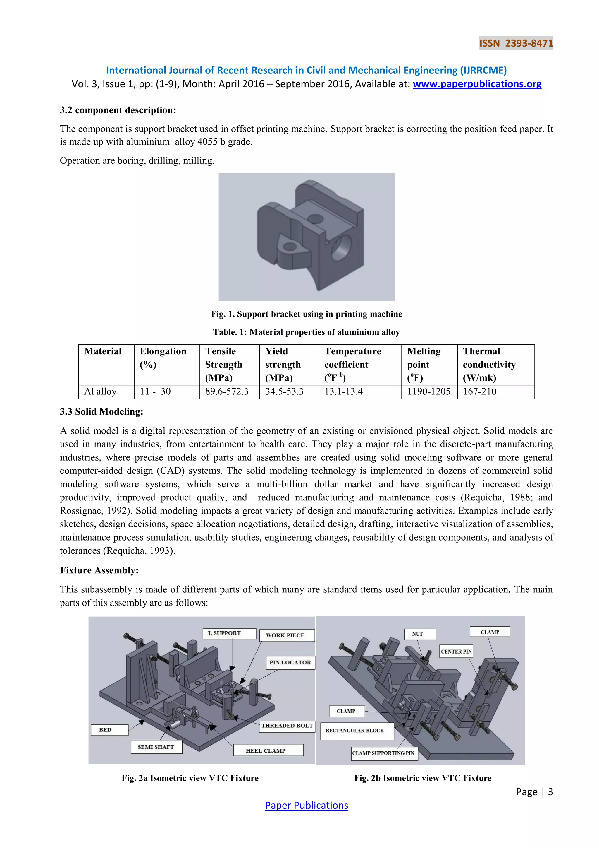
For making the machining fixture design it is required to study in detail about the component for which fixture is
designed and customer requirements.
3.1 customer requirement:
a. The requirement is a machining Fixture.
b. Five components loading at a time.
c. Loading and unloading of part using hand and it shouldn’t foul with either machine elements or fixture elements.
d. Fool proofing while loading component. Write-up of Interchangeable elements. Machining Accuracy should be within
50 microns.](https://image.slidesharecdn.com/designofmachiningfixture-685-170406083327/75/Design-of-Machining-Fixture-for-Support-Bracket-2-2048.jpg)
![ISSN 2393-8471
International Journal of Recent Research in Civil and Mechanical Engineering (IJRRCME)
Vol. 3, Issue 1, pp: (1-9), Month: April 2016 – September 2016, Available at: www.paperpublications.org
Page | 9
Paper Publications
REFERENCES
[1] N. P. Maniar, D.P. Vakharia, “Design & Development of Fixture for CNC-Reviews, Practices & Future Directions”,
International Journal of Scientific & Engineering Research Volume 4, Issue 2, February-2013.
[2] R.D.Makwana and N.D.Gosvami, “A Study on Fixture Design for Complex Part” International Journal of Futuristic
Trends in Engineering and Technology Vol. 1 (01), 2014.
[3] Necmettin Kaya, “Machining fixture locating and clamping position optimization using genetic algorithms” science
driect 2005
[4] P. FallboÈhmer, C.A. RodrõÂguez, T. OÈ zel, T. Altan, “High-speed machining of cast iron and alloy steels for die
and mold manufacturing” Journal of Materials Processing Technology 98 (2014)
[5] Tom Zacharia and M.S. Steve, “Design Optimization of Machining Fixture for the Slant Bed CNC Lathe
(SBCNC80/2000)”. International Journal of Mechanical Engineering and Research. ISSN No. 2249-0019, Volume 3,
Number 4 (2013)
[6] S. Selvakumar, K.P. Arulshri, K.P. Padmanaban and K.S.K. Sasikumar,“ Clamping Force Optimization for
Minimum Deformation of Workpiece” World Applied Sciences Journal 11 (7): 840-846, 2010 ISSN 1818-4952](https://image.slidesharecdn.com/designofmachiningfixture-685-170406083327/75/Design-of-Machining-Fixture-for-Support-Bracket-9-2048.jpg)


