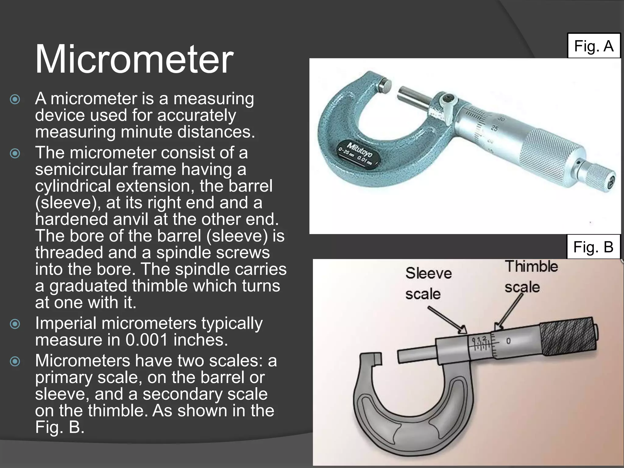
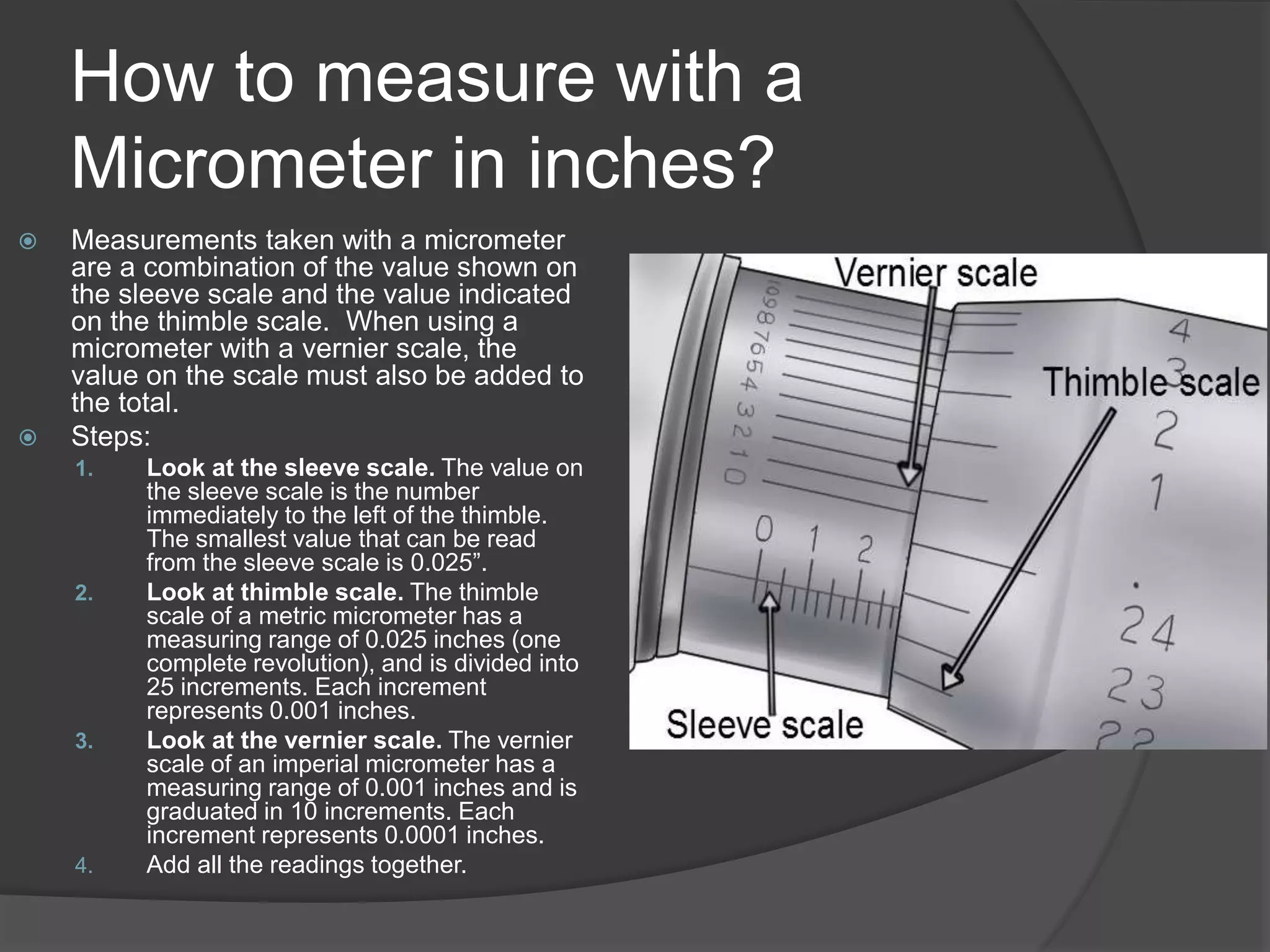
Prof. Justen Garner
CLT: Mr. Mohammed
New York City College of Technology
Date: 09-23-2019
Objectives:
 Learn how to take measurements with a
Micrometer.
 Material covered: Section C Unit 4
 Classwork Handout
Micrometer
 A micrometer is a measuring
device used for accurately
measuring minute distances.
 The micrometer consist of a
semicircular frame having a
cylindrical extension, the barrel
(sleeve), at its right end and a
hardened anvil at the other end.
The bore of the barrel (sleeve) is
threaded and a spindle screws
into the bore. The spindle carries
a graduated thimble which turns
at one with it.
 Imperial micrometers typically
measure in 0.001 inches.
 Micrometers have two scales: a
primary scale, on the barrel or
sleeve, and a secondary scale
on the thimble. As shown in the
Fig. B.
Fig. A
Fig. B
Micrometer
 Every time the spindle
makes a complete
revolution, the space
between the measuring
faces of the instrument
(the spindle and the anvil)
by 0.025 inch for imperial
micrometers.
 There a number of
different types of
micrometers. The most
common are the outside
micrometers. Inside
micrometers and depth
micrometers.
 They are widely used in
mechanical engineering for
accurately measuring
components.
Fig. C
Micrometer Parts
 Measuring FACES - The measured
items are put between the measuring
faces, the anvil and the spindle (also
called - measuring rods). The ANVIL is
the stationary measuring face against
which parts are held until the spindle
makes contact with the work.
 The threaded SPINDLE is the moving
measuring face of the tool. The spindle
extends from the thimble. As the user turns
the thimble, the spindle pushes the item to
be measured against the anvil.
 THIMBLE - The thimble refers to the
revolving portion of a gadget's handle.
Markings on the thimble revolve along
with the handle to align with the barrel's
scale and provide a measuring.
 LOCK NUT - The locking device secures
the spindle and preserves the measuring
so that the micrometer can be removed
from the workpiece before taking the
reading. Some of the gadgets have a
lock nut (as shown), while others may
have a locking lever.
Fig. D
Micrometer Parts
 SLEEVE (Barrel) scale - The barrel forms the
uppermost part of the handle; the part closest to
the frame's "U." The barrel is a cylindrical piece
of metal, integral to the frame; the frame and
barrel are molded as one piece. The barrel's
circumference features marks that indicate a
measuring. Because the micrometer-caliper
measures on a micro scale, its calculations are
often lengthy decimals.
 RATCHET speeder-stop - The ratchet speeder
increases the speed at which the spindle rotates,
so the space between the anvil and the spindle
is reduced more quickly than it would be if the
thimble were in use. Using the ratchet speeder
reduces the time it takes to use the gadget.
 The ratchet incorporates a slipping clutch
mechanism that prevents overtightening and
aids the user to apply a constant measuring
force to the spindle, helping to ensure reliable
measurements. If the force were to be excessive
then it would be possible to overstress the frame
thus causing permanent damage to the
micrometer which would in turn lead to incorrect
readings being obtained.
 FRAME - The frame is the basic element of any
micrometer-caliper. The frame appears as a
roughly U-shaped piece of metal. Etched upon
the frame's exterior is a legend, or list, explaining
the graduations indicated on the tool's barrel. A
handle protrudes from one side of the frame so
that its appearance resembles a small scythe.
Fig. D
How to measure with a
Micrometer in inches?
 Measurements taken with a micrometer
are a combination of the value shown on
the sleeve scale and the value indicated
on the thimble scale. When using a
micrometer with a vernier scale, the
value on the scale must also be added to
the total.
 Steps:
1. Look at the sleeve scale. The value on
the sleeve scale is the number
immediately to the left of the thimble.
The smallest value that can be read
from the sleeve scale is 0.025”.
2. Look at thimble scale. The thimble
scale of a metric micrometer has a
measuring range of 0.025 inches (one
complete revolution), and is divided into
25 increments. Each increment
represents 0.001 inches.
3. Look at the vernier scale. The vernier
scale of an imperial micrometer has a
measuring range of 0.001 inches and is
graduated in 10 increments. Each
increment represents 0.0001 inches.
4. Add all the readings together.
Ex. 1
Ex. 2
In Class Work:
 Finish the Vernier Caliper and
Micrometer reading.
 Whatever you do not finish in class, you will
finish for Homework.
Homework
 Read Sec. C Unit 4 – Complete Self test
on pgs. 133-135

Manufacturing process lab lecture 2

  • 1.
    Prof. Justen Garner CLT:Mr. Mohammed New York City College of Technology Date: 09-23-2019
  • 2.
    Objectives:  Learn howto take measurements with a Micrometer.  Material covered: Section C Unit 4  Classwork Handout
  • 3.
    Micrometer  A micrometeris a measuring device used for accurately measuring minute distances.  The micrometer consist of a semicircular frame having a cylindrical extension, the barrel (sleeve), at its right end and a hardened anvil at the other end. The bore of the barrel (sleeve) is threaded and a spindle screws into the bore. The spindle carries a graduated thimble which turns at one with it.  Imperial micrometers typically measure in 0.001 inches.  Micrometers have two scales: a primary scale, on the barrel or sleeve, and a secondary scale on the thimble. As shown in the Fig. B. Fig. A Fig. B
  • 4.
    Micrometer  Every timethe spindle makes a complete revolution, the space between the measuring faces of the instrument (the spindle and the anvil) by 0.025 inch for imperial micrometers.  There a number of different types of micrometers. The most common are the outside micrometers. Inside micrometers and depth micrometers.  They are widely used in mechanical engineering for accurately measuring components. Fig. C
  • 5.
    Micrometer Parts  MeasuringFACES - The measured items are put between the measuring faces, the anvil and the spindle (also called - measuring rods). The ANVIL is the stationary measuring face against which parts are held until the spindle makes contact with the work.  The threaded SPINDLE is the moving measuring face of the tool. The spindle extends from the thimble. As the user turns the thimble, the spindle pushes the item to be measured against the anvil.  THIMBLE - The thimble refers to the revolving portion of a gadget's handle. Markings on the thimble revolve along with the handle to align with the barrel's scale and provide a measuring.  LOCK NUT - The locking device secures the spindle and preserves the measuring so that the micrometer can be removed from the workpiece before taking the reading. Some of the gadgets have a lock nut (as shown), while others may have a locking lever. Fig. D
  • 6.
    Micrometer Parts  SLEEVE(Barrel) scale - The barrel forms the uppermost part of the handle; the part closest to the frame's "U." The barrel is a cylindrical piece of metal, integral to the frame; the frame and barrel are molded as one piece. The barrel's circumference features marks that indicate a measuring. Because the micrometer-caliper measures on a micro scale, its calculations are often lengthy decimals.  RATCHET speeder-stop - The ratchet speeder increases the speed at which the spindle rotates, so the space between the anvil and the spindle is reduced more quickly than it would be if the thimble were in use. Using the ratchet speeder reduces the time it takes to use the gadget.  The ratchet incorporates a slipping clutch mechanism that prevents overtightening and aids the user to apply a constant measuring force to the spindle, helping to ensure reliable measurements. If the force were to be excessive then it would be possible to overstress the frame thus causing permanent damage to the micrometer which would in turn lead to incorrect readings being obtained.  FRAME - The frame is the basic element of any micrometer-caliper. The frame appears as a roughly U-shaped piece of metal. Etched upon the frame's exterior is a legend, or list, explaining the graduations indicated on the tool's barrel. A handle protrudes from one side of the frame so that its appearance resembles a small scythe. Fig. D
  • 7.
    How to measurewith a Micrometer in inches?  Measurements taken with a micrometer are a combination of the value shown on the sleeve scale and the value indicated on the thimble scale. When using a micrometer with a vernier scale, the value on the scale must also be added to the total.  Steps: 1. Look at the sleeve scale. The value on the sleeve scale is the number immediately to the left of the thimble. The smallest value that can be read from the sleeve scale is 0.025”. 2. Look at thimble scale. The thimble scale of a metric micrometer has a measuring range of 0.025 inches (one complete revolution), and is divided into 25 increments. Each increment represents 0.001 inches. 3. Look at the vernier scale. The vernier scale of an imperial micrometer has a measuring range of 0.001 inches and is graduated in 10 increments. Each increment represents 0.0001 inches. 4. Add all the readings together.
  • 8.
  • 9.
  • 10.
    In Class Work: Finish the Vernier Caliper and Micrometer reading.  Whatever you do not finish in class, you will finish for Homework.
  • 11.
    Homework  Read Sec.C Unit 4 – Complete Self test on pgs. 133-135

Editor's Notes

  • #3 A few classwork problems will be given.
  • #4 Proper Use and Care for a Micrometer Be sure to unlock the locking lever before attempting to revolve the thimble. Clean the measuring faces with a clean cloth before and after measuring. It is also a good practice to occasionally clean the spindle to keep any contaminants from being drawn into the sleeve. Use the grip on the thimble when requiring a large amount of travel but as you come close to closing in on the item to be measured use the ratchet stop so as to not overtighten the thimble and give an erroneous reading. When a gadget is at its minimum reading the horizontal line on the sleeve should line up with the ‘0’ on the thimble. If that is not the case it will be necessary to calibrate the micrometer by revolving the sleeve. Each gadget comes with a half moon adjusting wrench for this purpose. To make the adjustment simply puzzle the wrench to the side of the spindle and insert the small tip into the leverage hole. It will not require much effort to turn the spindle however there is sufficient resistance in the spindle so that it will never move on its own. Larger gadgets are supplied with standards to check for correct calibration. When checking, be sure to hold the standard squarely betwixt the anvil and spindle. To help with this try revolving the standard slightly with your fingers while gently turning the thimble as you close in on the standard. Never leave a tool exposed in the hot sun (store it in a toolbox, in a quality shelf or a cabinet, that can be found and purchased in furniture stores) and then attempt a measuring procedure. This would also lead to an erroneous reading.
  • #5 Outside Micrometers - are utilized to determine outer ranges, like the thickness of sheet stock or outside diameters of round stock. The screw thread type of a gadget is a type of outside micrometer applied to measure not only the diameter of screws, but also the pitch of their threads. The item to be measured is situated betwixt the stationary end of the gadget, called the anvil, and the moving end, called the spindle. A knob, called a ratchet, is turned, pushing the spindle against the item. The thickness may be indicated by a mark on a vernier scale or by digital display. Inside micrometers - applied to determine the inner ranges of an item: the inner diameter of a tube, bushing, cylinder, etc. They consist of a gadget’s head, a set of extension rods, and in some cases a handle. The length of the head itself is what is measured, since it is situated within the diameter being calculated; the smallest heads available are one-quarter-inch. The extension rods are applied when the maximum length of the head is too small for the opening. The handle is utilized for inaccessible areas, and the diameter is read from a vernier scale or a digital display. Depth micrometers are used for measuring the depths of blind voids, grooves, recesses, etc. A flat surface at the top of the hole is required for the micrometer base to sit on, and the micrometer should be held firmly in place for an accurate reading. The ratchet is turned until the spindle touches the bottom of the hole, and the depth is read from the vernier scale or digital display.
  • #7 To overcome this problem the ratchet stop is fitted and this drives the thimble through a ratchet device.
  • #8 When reading the thimble scale, identify the number that aligns best with the index line on the sleeve scale.  If the index line falls between two values, the reading will be the number immediately below the index line. The reading on the vernier scale is the value that aligns best with any increment on the thimble scale.
  • #9 0.100 0.075 0.009 0.0004-Vernier Scale 0.1844
  • #10 0.300 0.050 0.006 0.0006-Vernier Scale 0.3566