Download to read offline


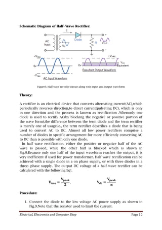
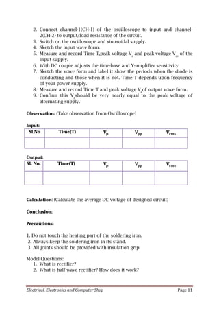
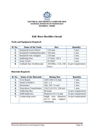

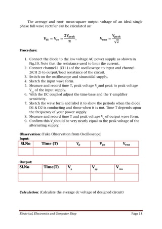


The document describes how to build and analyze a half-wave rectifier circuit using a diode, resistor, step-down transformer and cathode ray oscilloscope (CRO). It provides the schematic, components, procedure and expected observations. Key steps include: (1) Connecting the half-wave rectifier circuit and measuring the input waveform on the CRO. (2) Measuring the output pulsating DC waveform and confirming its peak voltage is nearly equal to the input peak voltage. (3) Recording time and voltage observations to analyze the rectification process and efficiency of converting the AC input to DC output.


