Download to read offline
![IOSR Journal of Mechanical and Civil Engineering (IOSR-JMCE)
e-ISSN: 2278-1684,p-ISSN: 2320-334X, Volume 12, Issue 4 Ver. III (Jul. - Aug. 2015), PP 87-94
www.iosrjournals.org
DOI: 10.9790/1684-12438794 www.iosrjournals.org 87 | Page
CFD Simulation of Flow around External Vehicle: Ahmed Body
Saurabh Banga1
, Md. Zunaid2*
, Naushad Ahmad Ansari3
, Sagar Sharma4
,
Rohit Singh Dungriyal5
Assistant Professor, Department of Mechanical Engineering, Delhi Technological University, Bawana Road,
Delhi, India2, 3
U.G Student, Department of Mechanical & Automobile Engineering, Delhi Technological University, Bawana
Road, Delhi, India1,4,5
Abstract: The main objective of this paper is to elucidate a solution to reduce the inefficiencies and losses
caused due to major parameters pertaining to the aerodynamics of road vehicle (drag, lift). This is
accomplished by investigating the variation of the rear slant angle of the Ahmed body and its effect on the drag
and lift coefficients and determine the optimum angle for least drag through numerical simulation. The
simplified vehicle geometry: Ahmed Reference Model has been used as a benchmark. The computational part
consists of numerical simulation of the flow around the Ahmedbody employing CFD (Computational Fluid
Dynamics) techniques. In numerical simulation results, pressure-based solver was utilized and the turbulence
model employed was k-Epsilon realizable model with non-equilibrium wall function for near wall treatment. The
designing of model used in this paper is done through the SOLIDWORKS ‘14; and CFD simulation carried out
in FLUENT (ANSYS 14).
Keywords: Ahmed body, CFD, k-Epsilon realizable model, Drag, Lift
I. Introduction
The pollution emerged by using volatile fuels in automobile has become a major concern pertaining to
the environment and economic viability. Different approaches such as improving the efficiency or usage of
alternative fuels for the vehicle have been considered. Advancement in some of the major areas such as
aerodynamics improvement, weight reduction and power increase has given us many feasible results, but
reducing aerodynamic factors such as drag, lift is more efficient than increasing the power of the vehicle or
decreasing the weight of the vehicle.
Automotive aerodynamics comprises of the study of aerodynamics of road vehicles. Its main goals are
reducing drag, minimizing noise emission, improving fuel economy, preventing undesired lift forces and
minimising other causes of aerodynamic instability at high speeds. Also, in order to maintain better control for
steering and braking, we look into design and aerodynamics of a vehicle. Drag is caused due to the pressure
difference between the frontal and the rear end of the vehicle. It can be reduced by modification of the design of
the vehicle or the modification of the air flow around the vehicle. 50% of the mechanical energy of the vehicle is
wasted to overcome drag at highway speed of nearly 88.5 to 96.5 kph. [1]
It is necessary, at times, to generate down force - to improve traction and thus cornering abilities.Lift
can be dangerous for an automobile, especially at high speeds. So, in order to maintain control for steering and
braking, cars are designed so that the automobile exerts a downward force as their speed increases. However,
increasing this downward force increases drag, which in turn, limits the top speed and increases fuel
consumption. Hence, these two forces must be carefully balanced.
Air has a tendency to curl downwards around the ends of a car, travelling upwards from the high-
pressure region under the car to the low-pressure region on top, at the rear end of the automobile and
subsequently collides with moving low-pressure air. The kinetic energy of these turbulent air spirals acts in a
direction that is negative relative to the direction of travel intended. Thus, the car engine must compensate for
the losses created by this drag. Vortices are released during flow separation and trail downstream to form
structured or unstructured wake patterns. A wake is the region of re-circulating flow immediately behind a
moving or stationary solid body, caused by the flow of surrounding fluid around the body. The local
disturbances in the flow pattern behind the vehicle causes a momentum loss thus causing form drag which
extends far behind the bodyworks of a vehicle.
The generic Ahmed Body reference model has been chosen as the benchmark for carrying out
computations for studying of the aerodynamic parameters. The body was first proposed by Ahmed et al., (1984).
[2]
The Ahmed body is a very simple bluff body which has its shape simple enough to allow for accurate flow
simulation but retains some important practical features relevant to automobile bodies. It has a slant on its rear
end, whose angle can be manipulated and the corresponding drag and lift coefficients calculated. This is done to
exhibit the air flow over the different geometry sections of an automobile and in its vicinity, at different slant](https://image.slidesharecdn.com/m012438794-160711060247/85/M012438794-1-320.jpg)
![IOSR Journal of Mechanical and Civil Engineering (IOSR-JMCE)
e-ISSN: 2278-1684,p-ISSN: 2320-334X, Volume 12, Issue 4 Ver. III (Jul. - Aug. 2015), PP 87-94
www.iosrjournals.org
DOI: 10.9790/1684-12438794 www.iosrjournals.org 87 | Page
CFD Simulation of Flow around External Vehicle: Ahmed Body
Saurabh Banga1
, Md. Zunaid2*
, Naushad Ahmad Ansari3
, Sagar Sharma4
,
Rohit Singh Dungriyal5
Assistant Professor, Department of Mechanical Engineering, Delhi Technological University, Bawana Road,
Delhi, India2, 3
U.G Student, Department of Mechanical & Automobile Engineering, Delhi Technological University, Bawana
Road, Delhi, India1,4,5
Abstract: The main objective of this paper is to elucidate a solution to reduce the inefficiencies and losses
caused due to major parameters pertaining to the aerodynamics of road vehicle (drag, lift). This is
accomplished by investigating the variation of the rear slant angle of the Ahmed body and its effect on the drag
and lift coefficients and determine the optimum angle for least drag through numerical simulation. The
simplified vehicle geometry: Ahmed Reference Model has been used as a benchmark. The computational part
consists of numerical simulation of the flow around the Ahmedbody employing CFD (Computational Fluid
Dynamics) techniques. In numerical simulation results, pressure-based solver was utilized and the turbulence
model employed was k-Epsilon realizable model with non-equilibrium wall function for near wall treatment. The
designing of model used in this paper is done through the SOLIDWORKS ‘14; and CFD simulation carried out
in FLUENT (ANSYS 14).
Keywords: Ahmed body, CFD, k-Epsilon realizable model, Drag, Lift
I. Introduction
The pollution emerged by using volatile fuels in automobile has become a major concern pertaining to
the environment and economic viability. Different approaches such as improving the efficiency or usage of
alternative fuels for the vehicle have been considered. Advancement in some of the major areas such as
aerodynamics improvement, weight reduction and power increase has given us many feasible results, but
reducing aerodynamic factors such as drag, lift is more efficient than increasing the power of the vehicle or
decreasing the weight of the vehicle.
Automotive aerodynamics comprises of the study of aerodynamics of road vehicles. Its main goals are
reducing drag, minimizing noise emission, improving fuel economy, preventing undesired lift forces and
minimising other causes of aerodynamic instability at high speeds. Also, in order to maintain better control for
steering and braking, we look into design and aerodynamics of a vehicle. Drag is caused due to the pressure
difference between the frontal and the rear end of the vehicle. It can be reduced by modification of the design of
the vehicle or the modification of the air flow around the vehicle. 50% of the mechanical energy of the vehicle is
wasted to overcome drag at highway speed of nearly 88.5 to 96.5 kph. [1]
It is necessary, at times, to generate down force - to improve traction and thus cornering abilities.Lift
can be dangerous for an automobile, especially at high speeds. So, in order to maintain control for steering and
braking, cars are designed so that the automobile exerts a downward force as their speed increases. However,
increasing this downward force increases drag, which in turn, limits the top speed and increases fuel
consumption. Hence, these two forces must be carefully balanced.
Air has a tendency to curl downwards around the ends of a car, travelling upwards from the high-
pressure region under the car to the low-pressure region on top, at the rear end of the automobile and
subsequently collides with moving low-pressure air. The kinetic energy of these turbulent air spirals acts in a
direction that is negative relative to the direction of travel intended. Thus, the car engine must compensate for
the losses created by this drag. Vortices are released during flow separation and trail downstream to form
structured or unstructured wake patterns. A wake is the region of re-circulating flow immediately behind a
moving or stationary solid body, caused by the flow of surrounding fluid around the body. The local
disturbances in the flow pattern behind the vehicle causes a momentum loss thus causing form drag which
extends far behind the bodyworks of a vehicle.
The generic Ahmed Body reference model has been chosen as the benchmark for carrying out
computations for studying of the aerodynamic parameters. The body was first proposed by Ahmed et al., (1984).
[2]
The Ahmed body is a very simple bluff body which has its shape simple enough to allow for accurate flow
simulation but retains some important practical features relevant to automobile bodies. It has a slant on its rear
end, whose angle can be manipulated and the corresponding drag and lift coefficients calculated. This is done to
exhibit the air flow over the different geometry sections of an automobile and in its vicinity, at different slant](https://image.slidesharecdn.com/m012438794-160711060247/75/M012438794-1-2048.jpg)
![CFD Simulation Of Flow Around External Vehicle: Ahmed Body
DOI: 10.9790/1684-12438794 www.iosrjournals.org 88 | Page
angles. This model portrays how to calculate the turbulent flow field around a simple car-like geometry using
the turbulent flow, k-epsilon interface.
Different rear slant angles result in the emergence of different wake regions at the rear, which are
mainly responsible for the drag of the vehicle. This paper has the following objectives:
1. To understand the drag and lift mechanism by conducting analysis on Ahmed body with 10 different angle
ranging from 0-40 degrees.
2. To exhibit and comprehend the velocity contours, focussing at the wake region of the body.
3. To portray pressure distribution over the entire Ahmed body.
II. Literature Review
Ahmed et al. (1984) [2]
analysed time averaged wake structure around the Ahmed body at a Reynolds
number equal to 1.2*106
by manipulating the rear slant angle in the range of 0-400
in increments of 50
. However,
the study did not yield information about unsteady flow characteristics of the flow around the Ahmed body.
Bayraktar et al. (2001) [3]
examined the external aerodynamics of Ahmed reference body for the rear
slant angles of 0, 12.5, and 25 degrees. The main concern was observing the effect on the lift and drag
coefficients due to variation of Reynolds number and calculating wind-averaged drag coefficients. The 10-inch
water column possessing an electronic scanning module coupled with a force balance system was utilized to
measure the pressure and forces which are consequently used to calculate the drag coefficients.
Spohn and Gillieron (2002) [4]
carried out experiments to investigate the flow characteristics of the
Ahmed body with the slant angle equal to 25 degree and the Reynolds number equal to 8.3*103
. The experiment
was carried out in a closed water tunnel, using the electrolyte precipitation technique at the front as well as the
rear of the Ahmed body.
M. Zunaid, Naushad Ahmad Ansari [5]
designed and implemented the curved boat tail configuration
without the AFC device on a generic SUV design working on the principle of Coanda effect, causing the airflow
over and under the SUV to take a curved path resulting in blowing of air in the immediate wake region. They
examined its effect on various aerodynamic parameters and reported an increase in the average pressure in the
wake region along with a significant drag reduction of 8.013 %.
Morelli et al. (1976) conceptualized and proposed a theoretical method to determine the optimum shape
of a passenger car body for minimum drag by imposing the condition that the total lift be zero. This study
proved that the aerodynamic drag can be reduced substantially without utilizing any additional devices by
optimizing the body shape. Morelli et al. (2000) [6]
proposed a new technique called “fluid tail”, obtainable by
addressing small power air jets in the wake, for application to the aerodynamic design of basic shape of a
passenger car. .
P. Drage et al (2008) [7]
conducted both CFD simulations as well as wind tunnel testing (T.U Graz wind
tunnel) on the Ahmed body with two rear slant angle configurations. The simulation was performed with the
Fluent and by using the Reynold Stress Model. The mesh was developed with the meshing tool SPIDER. It
consisted of 4 prism layers around the body and had an unstructured volume mesh giving a total cell count of
7.7 million cells. This type of meshing approach is commonly adopted as the time spent to create a structured
grid around real vehicle shapes would prevent engineers from operating within the strict deadlines imposed by
vehicle design cycles. For the 25° angle, a drag coefficient of 0.299 and a lift coefficient of 0.345 was obtained
from the wind tunnel experiment, while the CFD simulation resulted in the values of 0.295 and 0.387 for drag
and lift coefficient respectively. The RSM model showed an over estimation of the pressure coefficient over the
slant angle, when compared to the pressure measurement made by Lienhart and Becker (2003). [8]
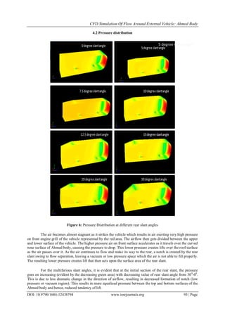
Figure 1: Geometry of Ahmed model](https://image.slidesharecdn.com/m012438794-160711060247/85/M012438794-2-320.jpg)
![CFD Simulation Of Flow Around External Vehicle: Ahmed Body
DOI: 10.9790/1684-12438794 www.iosrjournals.org 89 | Page
Han (1992) [9]
performed aerodynamic shape optimization on Ahmed body with three shape
parameters: backlight angle (0º to 30º), boat tail angle (0º to 30º) and ramp angle (0º to 20º). The k-ε turbulence
model CFD solver was coupled with an optimization routine. In this study, an analytic approximation function
of the objective function (drag coefficient values from CFD 28 analysis) was created in terms of the design
variables. The optimization was then performed on this approximation function and optimum parameters were
found. The CFD analysis was again performed with this optimum set of parameters and the objective function
was updated with new results. This process was continued until the parameters for minimum drag were
obtained. The optimization process revealed that the optimum rear body parameters are backlight angle of 17.80
;
boat-tail angle of 18.90
; and ramp angle of 9.20
. The determined values for minimum drag were found to lie
within the experimentally determined values of 15-180
backlight angles, 15-220
boat-tail angles and 9-140
ramp
angles. The drag coefficient was reduced from 0.209 for a square back to 0.110 for an optimized geometry.
However, the technique used for parameterization of geometry in this study cannot be applied to complex
geometries.
S. Kapadia et. al.[10]
conducted CFD analysis on the Ahmed body with the 25° slant angle configuration
using two different turbulence modelling approaches: Detached eddy simulation (DES) and single equation
unsteady RANS model. An unstructured volume mesh grid of 1.7 million cells was generated with Gridgen and
COBALT was used as a solver. Although both the models predict the presence of the counter rotating vortices,
the DES depicted a better representation of the unsteady structure at the trailing edge of the Ahmed body. The
drag coefficient reached a constant value after approximately 3 seconds of simulation for both DES and RANS.
DES showed an average Cd value of 0.2585 while with the RANS approach the drag the average Cd calculated
is 0.3272.
III. Numerical Simulation
The reference Ahmed Body is 1044mm long, 327mm wide and 288mm high. In ANSYS „14 Design
Modeller, a single body domain of air is created surrounding the Ahmed body walls after subtracting it from the
air enclosure. It has dimensions 5m from front, 7.5m from the rear and 3m from the top.
Figure 2: Single air body domain
3.1 Meshing
The “finite element method” technique is used in our problem. The ANSYS Meshing Tool is used for
carrying out the meshing. The model is 50 mm above the floor.
Details of the mesh are as follows: Relevance center: coarse, Smoothing: high, Transition: slow, Initial size
seed: Active assembly, Min. size: 1mm, Max. Size: 250mm, Advanced Size function: Proximity and Curvature.
Modifications in meshing:](https://image.slidesharecdn.com/m012438794-160711060247/85/M012438794-3-320.jpg)
![CFD Simulation Of Flow Around External Vehicle: Ahmed Body
DOI: 10.9790/1684-12438794 www.iosrjournals.org 90 | Page
Size of roller meshing is limited to 2mm.
Size of faces meshing is limited to 10mm.
Inflation Layer method [11]
of first aspect ratio of 5, growth rate of 20% of 5 layers is used.
3 different volumetric limit size boxes are created:
1. Car Box: Limits the size of mesh around Ahmed Body up to 15mm.
2. Wake Box: Limits the size of mesh around wake region up to 10mm.
3. Underbody Box: Limits the size of mesh under the body up to 10mm.
The mesh is composed of 2112223 tetrahedral elements. Figure 4 shows the generated mesh.
Figure 3: Mesh of Ahmed body
3.2 Steady Flow Numerical Simulation:
Computational resources for the steady flow numerical simulations are a Dell workstation (1 CPU 1.8
GHz and 8GB RAM) and Windows 8 OS.
Realizable k-epsilon model with non-equilibrium wall function for near wall treatment is used with
Inlet velocity V = 40m/s and turbulence intensity is about 1% and turbulence viscosity ratio is 10 at inlet,
turbulence intensity is about 5% and turbulence viscosity ratio is 10 at outlet. Density of air is 1.225 kg/m3
,
temperature is 288.16 K and viscosity is 1.7894e-05
kg/m4
. Boundary conditions are - uniform velocity at inlet,
uniform pressure at outlet, symmetry at lateral and at top wall of the model and moving wall at floor.
Solution method utilizes pressure-velocity coupling scheme as coupled with gradient: least square cell
based method, pressure as standard and setting the momentum, turbulence kinetic energy, turbulence dissipation
rate as first order upwind for the initial 100 iterations and correspondingly as second order upwind for the next
500 iterations. Moreover, turbulence viscosity factor is taken as 0.8 for the initial 100 iterations and
consequently taken as 0.95 for the remaining 500 iterations.
IV. Simulation Results
The drag and lift coefficients are calculated for the 10 different manipulations of rear slant angle of the
Ahmed body ranging from 00-
400
. The minimum drag is obtained for the rear slant angle, φ= 7.5 degree for the
attached flow range of angles which exists up to 300
and thereafter, the flow becomes unattached at rear slant
and correspondingly the values of drag and lift tend to be randomly dispersed.](https://image.slidesharecdn.com/m012438794-160711060247/85/M012438794-4-320.jpg)
![CFD Simulation Of Flow Around External Vehicle: Ahmed Body
DOI: 10.9790/1684-12438794 www.iosrjournals.org 91 | Page
Table 1: Steady flow numerical simulation results
The table portrays our findings indicating that drag coefficient continually decreases from 00
reaching a
minimum at 7.50
and then continually increases for the attached flow range up to 300
.
Moreover, the lift coefficient linearly increases as the rear slant angle is increased from 00
up till 300
transitioning from negative (also called „downforce‟) to positive value of lift. The lift coefficient approaches
zero value at 7.50
. [12]
Figure 4: Graph between drag & lift coefficients and different rear slant angles
The drag and lift coefficients are plotted on a graph (above). It is observed that the lift coefficient
follows a linear increasing trend for rear slant angle ranging 0-200
. The minimum positive lift of 0.0292 is
obtained for rear slant angle of 7.50
. Also, the drag coefficient decreases as rear slant is increased from 00
up to
7.50
, where it reaches the minimum value of 0.2346 and then continually goes on increasing till 300
.
Beyond 300
, flow separation occurs and evidently drag and lift coefficient become randomly dispersed.
Rear slant angle (φ) (In degrees) Cd Cl
0 2.50031e-01 -1.17457e-01
5 2.37215e-01 -1.49709e-02
7.5 2.34631e-01 2.92149-02
10 2.36738e-01 8.29710e-02
12.5 2.41644e-01 1.32483e-01
15 2.46833e-01 1.85001e-01
20 2.61934e-01 2.83622e-01
30 2.97872e-01 3.47783e-01
35 2.94980e-01 2.05502e-01
40 2.50360e-01 8.36791e-03](https://image.slidesharecdn.com/m012438794-160711060247/85/M012438794-5-320.jpg)
![CFD Simulation Of Flow Around External Vehicle: Ahmed Body
DOI: 10.9790/1684-12438794 www.iosrjournals.org 94 | Page
V. Conclusion
CFD results for multifarious manipulations of the rear slant angle of the Ahmed Body are presented
after the geometries are designed and then developed. Comparison and examination by plotting a graph of the
lift and drag coefficients obtained for the numerous manipulations is done to determine the optimum rear slant
angle giving minimum drag coefficient. The following conclusions can be drawn from the results:
1. The minimum coefficient of drag (Cd) of 0.2346 is obtained with configuration of Ahmed Body with 7.5
degree rear slant angle.
2. The drag increases as the rear slant angle is reduced and increased from 7.50
down to 00
and up to 300
respectively.
3. The minimum positive coefficient of lift (Cl) of 0.0292 is obtained with configuration of Ahmed Body
with 7.5 degree rear slant angle.
4. The lift coefficient constantly goes on increasing with increasing rear slant angle, for the attached flow
range and it follows an almost linear trend for the 00
-200
range of angles, becoming non-linear thereafter.
5. The drag and lift coefficient becomes randomly dispersed after the flow becomes unattached after
increasing rear slant angle to 300
and beyond.
References
[1]. „Sustainable ground transportation – review of technologies, challenges and opportunities‟, Ramesh K. Agarwal, Department of
Mechanical Engineering & Materials Science, Washington University in St. Louis, MO 63130, USA.
[2]. „Some Salient Features of the Time – Averaged Ground Vehicle Wake‟, (SAE-TP-840300) Ahmed, S.R., Ramm, G., Faitin, G.,
1984. Society of Automotive Engineers, Inc., Warrendale, PA.
[3]. „Experimental and Computational Investigation of Ahmed Body for Ground Vehicle Aerodynamics‟, I. Bayraktar, D. Landman,
and O. Baysal, SAE Technical Paper 2001-01-2742, 2001, doi:10.4271/2001-01-2742.
[4]. „Flow Separations Generated by a Simplified Geometry of an Automotive Vehicle‟, A.Spohn, P. Gillieron, IUTAM Symposium:
Unsteady Separated Flows, April 8-12, 2002, Toulouse, France.
[5]. „Numerical Study of the Generic Sports Utility Vehicle Design with a Drag Reduction Add-On Device‟,Shubham Singh, M.
Zunaid, Naushad Ahmad Ansari, Shikha Bahirani, Sumit Dhall, Sandeep Kumar, Department of Mechanical Engineering, Delhi
Technological University, Hindawi Publishing Corporation Journal of Computational Engineering Volume 2014, Article ID
785294.
[6]. „A New Aerodynamic Approach to Advanced Automobile Basic Shapes‟, A. Morelli, SAE Technical Paper 2001-01-0491, 2001.
[7]. „Efficient Use of Computational Fluid Dynamics for the Aerodynamic Development Process in the Automotive Industry‟, P. Drage,
A. Grabiel and G. Lindbichler, AIAA 2008-6735.
[8]. „Flow and turbulence structures in the wake of a simplified car model (Ahmed Model)‟, H. Lienhart, C. Soots and S. Becker, SAE
Technical Paper 2003-01- 0656, 2003.
[9]. „Optimization of bluff body for minimum Drag in ground proximity‟, T. Han, D. C. Hammond, C. J. Sagi, AIAA Journal, Vol. 30,
No. 4 (1992), pp. 882-889, doi: 10.2514/3.11005.
[10]. „Characterization of a square back Ahmed body near wake flow‟, A. Lahayea, A. Leroya & A. Kourtaa, 21`eme Congress Francis
de M´ecanique.
[11]. „Best practice guidelines for handling Automotive External Aerodynamics with FLUENT‟, Version 1.2 (Feb 9th 2005), Marco
Lanfrit, Fluent Deutschland GmbH Birkenweg 14a 64295 Darmstadt/Germany.
[12]. „Investigation of relationship between drag and lift coefficients for a generic car model‟, Ivan Dobrev, Fawaz Massouh,
BULTRANS-2014, Sep 2014, Sozopol, Bulgaria. BULTRANS 2014 Proceedings, pp.171-174. <Hal-01082895>
[13]. „Experimental investigation and numerical simulation of the flow around an automotive model: Ahmed body‟, Ivan Korkischko &
Julio Romano Meneghini, 19th International Congress of Mechanical Engineering, November 5-9, 2007, Brasília, DF.
[14]. „Numerical modeling of airflow over the Ahmed body’, Y. Liu, Alfred Moser Air and Climate Group, Swiss Federal Institute of
Technology, ETH-Zentrum WET A1, CH-8092 Zurich, Switzerland.
[15]. „Fundamental of Aerodynamics‟, 5th
edition, John D. Anderson, McGraw-Hill Book Co.](https://image.slidesharecdn.com/m012438794-160711060247/85/M012438794-8-320.jpg)

This document summarizes a computational fluid dynamics (CFD) simulation of flow around an Ahmed body, which is a simplified vehicle model used to study automotive aerodynamics. The simulation varied the rear slant angle of the Ahmed body from 0 to 40 degrees and analyzed the effects on drag and lift coefficients to determine the optimal angle for minimum drag. Pressure-based solver and k-Epsilon turbulence model were used in the simulation conducted in ANSYS Fluent. The study aimed to better understand drag and lift mechanisms and flow patterns like wake regions behind the vehicle body.