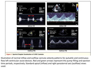
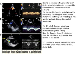
Echocardiography plays an important role in managing patients with left ventricular assist devices (LVADs). It is used pre-operatively to assess cardiac structure and function and plan the surgery. Intra-operatively, echo guides LVAD placement and activation to ensure proper positioning and function with no complications. Post-operatively, echo monitors ventricular size and function, valvular function, pump parameters like flow, and detects any complications. It is invaluable for optimizing LVAD settings and management of patients supported by these devices.

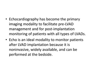
![• Doppler markers of pulmonary artery pressures
have been shown to significantly decrease with
LVAD support.
• These include the peak velocity of the TR jet
(proportional to pulmonary artery systolic
pressure), the pulmonary vein acceleration time
(inversely proportional to mean pulmonary artery
pressure), and estimated pulmonary vascular
resistance (PVR) using the Abbas formula
[(maximum tricuspid velocity/RV outflow tract
time-velocity integral) x 10 + 0.16].](https://image.slidesharecdn.com/lvadechomeet-211024181027/85/Lvad-left-ventricular-assist-device-echo-40-320.jpg)
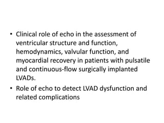
![• In patients supported by continuous-flow devices,
increasing device support can unload the LV to a point
where LV systolic pressure is less than mean arterial
pressure. This causes continuous AV closure.
• The speed setting at which this occurs is related in part
to underlying LV contractility.
• The ability to maintain AV opening above relatively
high levels of continuous pump support (i.e., Heart-
Mate II [Thoratec Corp.] pump speed 10,000 RPM vs.
9,000 RPM) was noted in patients who had successful
elective LVAD explantation.](https://image.slidesharecdn.com/lvadechomeet-211024181027/85/Lvad-left-ventricular-assist-device-echo-53-320.jpg)