Download to read offline


![PI controller
K P and K i are
proportional and integral
gain parameters of the
PI speed controller
T (n) = T (n-1) * + KP [ω re (n) - ω re(n-1) ] + K i ω re (n)](https://image.slidesharecdn.com/electricmotors6-120829142801-phpapp01/85/Electricmotors6-20-320.jpg)
![PID Controller
T (n) = T (n-1) * +KP [ω re(n) - ω re(n-1) ] + K i ω re(n) +
K d [ω re (n) - 2 ω re(n-1) + ω re(n-2) ]](https://image.slidesharecdn.com/electricmotors6-120829142801-phpapp01/85/Electricmotors6-21-320.jpg)


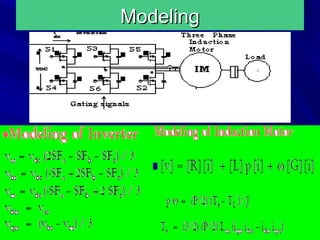


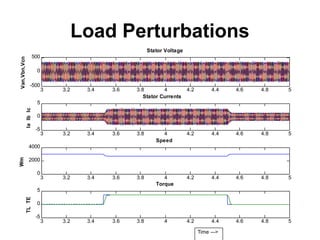


The document details a call for research projects aimed at final year engineering students specializing in electrical and electronics disciplines, emphasizing the guidance of experts in assembling hardware for projects related to vector control of induction motors. It discusses the historical development of polyphase induction machines, the advantages of vector control, and introduces various controllers, including PI, PID, and fuzzy logic controllers, with their operational principles and applications. Additionally, it includes literature references to foundational works in the field, highlighting the importance of control techniques in achieving effective motor performance.