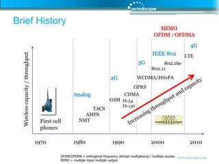
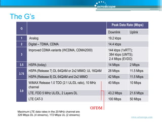
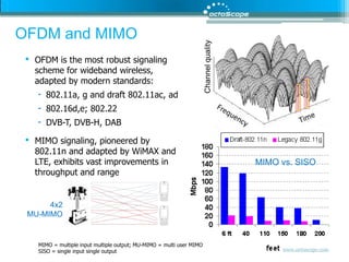
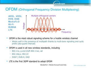
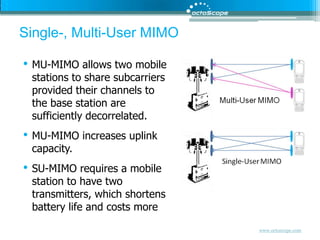
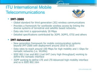
1) The document discusses mobile broadband technologies including a history of cellular standards and the evolution of OFDM, OFDMA, MIMO and LTE.
2) It provides an overview of key wireless standards organizations including 3GPP, IEEE 802, and how they developed technologies such as HSPA, WiMAX, and LTE.
3) The document focuses on physical layer technologies for mobile broadband including OFDM, OFDMA, MIMO techniques and how they are implemented in standards like 802.11, WiMAX and LTE.
1. Making Sense of Mobile Broadband Interop/NYC November 2009 Fanny Mlinarsky, octoScope
2. ITU World Telecommunications ICT Indicators – Oct 2009 4.6 billion subscriptions globally by end of 2009 Per 100 inhabitants Source: ITU World ICT Indicators, October 2009 * = estimated ICT = information and communications technology
3. Agenda The G’s – historical perspective OFDM, OFDMA and multiple antenna techniques Standards – 3GPP, IEEE 802 wireless White Spaces Concluding thoughts
4. Brief History MIMO OFDM / OFDMA 4G IEEE 802 LTE 3G 802.16e 802.11 2G WCDMA/HSxPA GPRS Wireless capacity / throughput Analog CDMA GSM Increasing throughput and capacity IS-54 IS-136 TACS AMPS NMT First cell phones 1970 1980 1990 2000 2010 OFDM/OFDMA = orthogonal frequency domain multiplexing / multiple access MIMO = multiple input multiple output
5. Handset Evolution Handsets are evolving to run mobile applications, such as video, Internet access, VoIP, location and other services… … enabled by new generation radios, such as 3G/WCDMA and emerging 3.9G/LTE Performance and roaming behavior are currently measured primarily for circuit voice services Performance of emerging mobile applications is little understood Battery life of 3G and 4G radios need to be carefully qualified as a function of use cases and handover scenarios The number of use cases and test cases is growing exponentially
6. Femtocell Ethernet xDSL, Cable Metro Ethernet Wi-Fi Broadband IP access Home AP/router ? Femtocells allow the use of ordinary cell phones over broadband IP access Wi-Fi enabled cell phones can work via Wi-Fi APs
7. Data Networks vs. Traditional Cellular Networks HLR VLR PSTN MSC 2 GMSC VLR IP Network Cellular Network MSC 1 BSC Today’s cellular infrastructure is set up for thousands of BSCs, not millions of femtocells. MSC = Mobile Switching Center GMSC = Gateway Mobile Switching Center
8. HSPA and HSPA+ HSPA+ is aimed at extending operators’ investment in HSPA 2x2 MIMO, 64 QAM in the downlink, 16 QAM in the uplink Data rates up to 42 MB in the downlink and 11.5 MB in the uplink. HSPA+ is CDMA-based and lacks the efficiency of OFDM Traditional HSPA One tunnel HSPA One tunnel HSPA+ One-tunnel architecture flattens the network by enabling a direct transport path for user data between RNC and the GGSN, thus minimizing delays and set-up time GGSN Gateway GPRS Support Node GGSN GGSN Control Data Serving GPRS Support Node SGSN SGSN SGSN Radio Network Controller RNC RNC User Data RNC Node B Node B Node B
10. Billing/OSS QoS QoS Presence QoS Presence Billing/OSS Billing/OSS Presence Traditional “Stovepipe” IMS … Voice Internet Voice Internet Video … IMS Network Traditional Cellular Network Stovepipe model – replicates functionality IMS – common layers facilitate adding services IMS = Internet Multimedia Subsystem
11. The G’s OFDM Maximum LTE data rates in the 20 MHz channel are 326 Mbps DL (4 streams), 172 Mbps UL (2 streams)
12. Agenda The G’s – historical perspective OFDM, OFDMA and multiple antenna techniques Standards – 3GPP, IEEE 802 wireless White Spaces Concluding thoughts
13. OFDM and MIMO OFDM is the most robust signaling scheme for wideband wireless, adapted by modern standards: 802.11a, g and draft 802.11ac, ad 802.16d,e; 802.22 DVB-T, DVB-H, DAB MIMO signaling, pioneered by 802.11n and adapted by WiMAX and LTE, exhibits vast improvements in throughput and range MIMO vs. SISO Channel quality 4x2 MU-MIMO MIMO = multiple input multiple output; MU-MIMO = multi user MIMO SISO = single input single output
14. OFDM (Orthogonal Frequency Division Multiplexing) Multiple orthogonal carriers ADSL, VDSL DVB, DAB MediaFLO Wi-Fi WiMAX LTE Voltage Frequency OFDM is the most robust signaling scheme for a hostile wireless channel Works well in the presence of multipath thanks to multi-tone signaling and cyclic prefix (aka guard interval) OFDM is used in all new wireless standards, including 802.11a, g and draft 802.11ac, ad 802.16d,e; 802.22 DVB-T, DVB-H, DAD LTE is the first 3GPP standard to adopt OFDM MediaFLO = Media Forward Link Only
15. Cyclic Prefix Guard interval > delay spread in the channel Useful data TS copy The OFDM symbol is extended by repeating the end of the symbol in the beginning. This extension is called the Cyclic Prefix (CP). CP is a guard interval that allows multipath reflections from the previous symbol to settle prior to receiving the current symbol. CP has to be greater than the delay spread in the channel. CP eliminates Intersymbol Interference (ISI) and makes the symbol easier to recover.
16. OFDMA (Orthogonal Frequency Division Multiple Access) OFDM is a modulation scheme OFDMA is a modulation and access scheme Time WiMAX LTE Time Frequency Frequency per user is dynamically allocated vs. time slots Frequency allocation per user is continuous vs. time User 1 User 2 User 3 User 4 User 5
17. FDD (frequency division duplex) Paired channels TDD (time division duplex) Single frequency channel for uplink an downlink Is more flexible than FDD in its proportioning of uplink vs. downlink bandwidth utilization Can ease spectrum allocation issues DL UL DL UL FDD and TDD Support
18. Time OFDMA symbol number Subchannel Frequency WiMAX TDD Transmission
21. 180 kHz, 12 subcarriers with normal CP User 2 User 1 User 3 User 2 0.5 ms 7 symbols with normal CP User 2 User 1 User 3 User 2 User 3 User 3 User 2 User 2 Time User 2 User 3 User 1 User 2 User 1 User 3 User 1 User 1 Resource Block (RB) Frequency LTE Resource Allocation Resources are allocated per user in time and frequency. RB is the basic unit of allocation. RB is 180 kHz by 0.5 ms; typically 12 subcarriers by 7 OFDM symbols, but the number of subcarriers and symbols can vary based on CP CP = cyclic prefix, explained ahead
22. Resource Block A resource block (RB) is a basic unit of access allocation. RB bandwidth per slot (0.5 ms) is 12 subcarriers times 15 kHz/subcarrier equal to 180 kHz. 1 slot, 0.5 ms … Resource block 12 subcarriers … … Subcarrier (frequency) 1 subcarrier Resource Element 1 subcarrier QPSK: 2 bits 16 QAM: 4 bits 64 QAM: 6 bits v … Time
23. Channel bandwidth in MHz Transmission bandwidth in RBs Center subcarrier (DC) not transmitted in DL Channel bw MHz Transmission bw # RBs per slot LTE Scalable Channel Bandwidth
25. OFDMA vs. SC-FDMA (LTE Uplink) Multi-carrier OFDM signal exhibits high PAPR (Peak to Average Power Ratio) due to in-phase addition of subcarriers. Power Amplifiers (PAs) must accommodate occasional peaks and this results low efficiency of PAs, typically only 15-20% efficient. Low PA efficiency significantly shortens battery life. To minimize PAPR, LTE has adapted SC-FDMA (single carrier OFDM) in the uplink. SC-FDMA exhibits 3-6 dB less PAPR than OFDMA. In-phase addition of sub-carriers creates peaks in the OFDM signal
26. 15 kHz subcarrier OFDMA symbols Downlink – lower symbol rate Time Uplink – higher symbol rate, lower PAPR SC-FDMA symbols … S1 S2 S3 S4 S5 S6 S7 S8 60 kHz Sequence of symbols Time Frequency SC-FDMA vs. OFDMA
27. Multiple Antenna Techniques SISO (Single Input Single Output) Traditional radio MISO (Multiple Input Single Output) Transmit diversity Space Time Block Coding (STBC), Space Frequency Block Coding (SFBC), Cyclic Delay Diversity (CDD) SIMO (Single Input Multiple Output) Receive diversity Maximal Ratio Combining (MRC) MIMO (Multiple Input Multiple Output) Spatial Multiplexing (SM) to transmit multiple streams simultaneously Works best in high SINR environments and channels de-correlated by multipath Transmit/Receive diversity Used in low SNR conditions
28. Receive and Transmit Diversity Receive diversity, MRC, makes use of the highest signal quality, combining signals from both antennas Transmit diversity techniques, STBC, SFBC or CDD, spread the signal so as to create artificial multipath to decorrelate signals from different antennas. Peak Null
29. Single-, Multi-User MIMO MU-MIMO allows two mobile stations to share subcarriers provided their channels to the base station are sufficiently decorrelated. MU-MIMO increases uplink capacity. SU-MIMO requires a mobile station to have two transmitters, which shortens battery life and costs more
30. Agenda The G’s – historical perspective OFDM, OFDMA and multiple antenna techniques Standards – 3GPP, IEEE 802 wireless White Spaces Concluding thoughts
31. IMT-2000 Global standard for third generation (3G) wireless communications Provides a framework for worldwide wireless access by linking the diverse systems of terrestrial and satellite based networks. Data rate limit is approximately 30 Mbps Detailed specifications contributed by 3GPP, 3GPP2, ETSI and others IMT-Advanced New generation framework for mobile communication systems beyond IMT-2000 with deployment around 2010 to 2015 Data rates to reach around 100 Mbps for high mobility and 1 Gbps for nomadic networks (i.e. WLANs) IEEE 802.11ac and 802.11ad VHT (very high throughput) working to define the nomadic interface 3GPP working to define LTE and LTE-Advanced high mobility interface and so is IEEE 802.16m ITU International Mobile Telecommunications
32. Japan USA 3GPP (3rd Generation Partnership Project) Partnership of 6 regional standards groups that translate 3GPP specifications to regional standards Defines standards for mobile broadband, including UMTS and LTE
33. The IEEE 802 Wireless Technologies WAN GSM, CDMA, UMTS… 3GPP Personal 802.15.3 Bluetooth 60 GHz UWB MAN Wide LAN TVWS PAN 802.22 RAN Regional White Spaces? 802.11 Wi-Fi Metro Local 802.16 WiMAX
34. IEEE 802 LAN/MAN Standards Committee (LMSC) 802.1 Higher Layer LAN Protocols 802.3 Ethernet 802.11 Wireless LAN 802.15 Wireless Personal Area Network 802.16 Broadband Wireless Access 802.17 Resilient Packet Ring 802.18 Radio Regulatory TAG 802.19 Coexistence TAG 802.21 Media Independent Handoff 802.22 Wireless Regional Area Networks Wireless standards dominate the work of IEEE 802 Work on TV White Spaces TAG = technical advisory group
35. History of IEEE 802.11 1989: FCC authorizes ISM bands(Industrial, Scientific and Medical) 900 MHz, 2.4 GHz, 5 GHz 1990: IEEE begins work on 802.11 1994: 2.4 GHz products begin shipping 1997: 802.11 standard approved 1998: FCC authorizes the UNII (Unlicensed National Information Infrastructure) Band - 5 GHz 1999: 802.11a, b ratified 2003: 802.11g ratified 2006: 802.11n draft 2 certification by the Wi-Fi Alliance begins 2009: 802.11n certification 20??: 802.11 ac/ad: 1 Gbps Wi-Fi 802.11 has pioneered commercial deployment of OFDM and MIMO – key wireless signaling technologies
38. IEEE 802.11 Active Task Groups TGp – Wireless Access Vehicular Environment (WAVE/DSRC) TGs – ESS Mesh Networking TGu – InterWorking with External Networks TGv – Wireless Network Management TGz – Direct Link Setup TGaa– Robust streaming of AV Transport Streams TGac– VHTL6 (very high throughput < 6 GHz) TGad– VHT 60 GHz http://grouper.ieee.org/groups/802/11
39. TGa TGe TGg TGc TGd TGh TGb TGb-cor1 TGi TGj 1997 1998 1999 2000 2001 2002 2003 2004 2005 2006 2007 2008 2009 2010 IEEE 802.11 Timeline TGk TGma TGn TGp Part of 802.1 TGr TGs TGT withdrawn TGF TGu TGv TGw TGy 802.11-1999 IEEE Standard April 1999 802.11-2007 IEEE Standard June 2007 802.11-1997 IEEE Standard July 1997
40. Making 802.11 Enterprise-grade 802.11r Fast Roaming √released 802.11k Radio Resource Measurement √released 802.11v Wireless Network Management
41. 802.11r Fast Transition (Roaming) Needed by voice applications Basic methodology involves propagating authentication information for connected stations through the ‘mobility domain’ to eliminate the need for re-authentication upon station transition from one AP to another The station preparing the roam can setup the target AP to minimize the actual transition time
42. 802.11k Radio Resource Measurement Impetus for 802.11k came from the Enterprises that needed to manage their WLANs from a central point 802.11k makes a centralized network management system by providing layer 2 mechanisms for Discovering network topology Monitoring WLAN devices, their receive power levels, PHY configuration and network activity Can be used to assists 802.11r Fast Transition (roaming) protocol with handoff decisions based on the loading of the infrastructure, but 802.11v is more focused on load balancing
43. 802.11v Wireless Network Management TGv’s charter is to build on the network measurement mechanisms defined by TGk and introduce network management functions to provide Enterprises with centralized network management and load balancing capabilities. Major goals: manageability, improved power efficiency and interference avoidance Defines a protocol for requesting and reporting location capability Location information may be CIVIC (street address) or GEO (longitude, latitude coordinates) For the handset, TGv may enable awareness of AP e911 capabilities while the handset is in sleep mode; this work has common ground with TGu
44. Making Wi-Fi Carrier-grade 802.11u - InterWorking with External Networks Main goal is to enable Interworking with external networks, including other 802 based networks such as 802.16 and 802.3 and 3GPP based IMS networks Manage network discovery, emergency call support (e911), roaming, location and availability The network discovery capabilities give a station looking to connect information about networks in range, service providers, subscription status with service providers 802.11u makes 802.11 networks more like cellular networks where such information is provided by the infrastructure
45. 802.11p is the PHY in the Intelligent Transportation Systems (ITS) WAVE/DSRC is the method for vehicle to vehicle and vehicle to road-side unit communications to support… Public safety, collision avoidance, traffic awareness and management, traveler information, toll booth payments Operates in the 5.9 GHz frequency band dedicated by the FCC for WAVE/DSRC This band falls right above the 802.11a band, making it supportable by the commercial 802.11a chipsets DSRC = Dedicated Short Range Communications WAVE = Wireless Access Vehicular Environment 802.11p WAVE/DSRC
46. IEEE 802.11s Mesh Wireless Distribution System with automatic topology learning and wireless path configuration Self-forming, self-healing, dynamic routing ~32 nodes to make routing algorithms computationally manageable Extension of 802.11i security and 802.11e QoS protocol to operate in a distributed rather than centralized topology MP (Mesh Point) Mesh Portal
47. History of IEEE 802.16 From OFDM to OFDMA orthogonal frequency division multiplexing orthogonal frequency division multiple access 1998: IEEE formed 802.16 WG Started with 10–66 GHz band; later modified to work in 2–11GHz to enable NLOS (non-line of site) 2004: IEEE 802.16‐2004d Fixed operation standard ratified 2005: 802.16-2005e Mobility and scalability in 2–6 GHz Latest: P802.16-2009 (Rev2) Future: 802.16m – next generation
48. IEEE 802.16 Active Task Groups 802.16h, License-Exempt Task Group Working with 802.11 TGy and 802.19 Coexistence TAG 802.16m, IMT Advanced Air Interface Maintenance Completed 802.16 Rev2 Working with the WiMAX Forum http://grouper.ieee.org/groups/802/16
49. WiMAX Forum IEEE 802.16 contains too many options The WiMAX Forum defines certification profiles on parts of the standard selected for deployment; promotes interoperability of products through testing and certification The WiMAX Forum works closely with the IEEE 802.16 Maintenance group to refine the standard as the industry learns from certification testing Future
50. Agenda The G’s – historical perspective OFDM, OFDMA and multiple antenna techniques Standards – 3GPP, IEEE 802 wireless White Spaces Concluding thoughts
51. TV White Spaces 6 MHz TV channels 2-69 VHF: 54-72, 76-88, 174-216 MHz UHF: 470-806 MHz November 4, 2008 FCC allowed unlicensed use of TV white spaces June 12, 2009 transition from analog to digital TV freed up channels 52-69 (above 692 MHz) due to higher spectral efficiency of digital TV TVBD = TV Band Device
52. White Spaces Radio Technology FCC Docket 04-186 requires the use of cognitive radio technology to determine whether a channel is available prior to transmitting. Methods for detecting licensed transmissions: An internal GPS could be used in conjunction with a database to determine whether the TVBD is located far enough away from licensed stations. TVBD could incorporate sensing capabilities to detect whether licensed transmitters are in its range. If licensed devices are detected, the TVBD would have to search for another channel.
53. FCC Rules TVBDs require geolocation capability and Internet access to a database of protected radio services. The TVBDs must first access the database before operating. Fixed devices can operate on any channel between 2 and 51, except 3, 4 and 37 Up to 4 Watts EIRP (Effective Isotropic Radiated Power) Channels 2 – 20 are restricted for use by fixed devices to protect wireless microphones Fixed and personal portable devices must sense TV broadcasting and wireless microphone signals
54. Frequency Allocation of TV Channels by the FCC Fixed TVBDs only *Channel 37 (608-614 MHz) is reserved for radio astronomy **Shared with public safety http://www.fcc.gov/mb/engineering/usallochrt.pdf
56. Beach-front Property? Lower frequencies experience lower attenuation in free space and through obstructions, e.g. buildings However, when propagating through metal frames in modern buildings, Fresnel zone gets constricted and attenuation is introduced Antenna – optimum length is a multiple of ¼ wavelength 3.3 feet for 70 MHz 4” for 700 MHz 1” for 2.4 GHz Longer antennas required for UHF may be problematic for handheld devices
57. Antenna Fresnel Zone r r = radius in feet D = distance in miles f = frequency in GHz D Fresnel zone is the shape of electromagnetic signal and is a function of frequency Constricting the Fresnel zone introduces attenuation and signal distortion Example: D = 0.5 mile r = 30 feet for 700 MHz r = 16 feet for 2.4 GHz r = 10 feet for 5.8 GHz
58. Hidden Node Scenario TV signal attenuated by an obstruction (wall) is undetectable by a TVBD. TVBD transmits, interfering with TV broadcast, which is received unobstructed by a rooftop antenna. TV broadcast received by an unobstructed rooftop TV antenna
59. White Spaces Communications Standards IEEE 802.22 Based on 802.16d Ongoing effort for almost 5 years Worked with the FCC on White Spaces regulations IEEE 802.19 Coexistence standards IEEE 802.11 TVWS Study Group
60. Agenda The wireless G’s – historical perspective OFDM, OFDMA and multiple antenna techniques Standards – 3GPP, IEEE 802 wireless White Spaces Concluding thoughts
61. Challenges on the Horizon Wireless infrastructure Support millions of small cells (femto, pico) Manage interference among base stations Manage coexistence among diverse standards, including White Spaces Mobile terminals Support multiple radio standards Roaming and handoff Application and network performance Cost, size, weight and battery life
62. To Learn More… Articles, white papers, test reports and presentations http://www.octoscope.com/English/Resources/Articles.html Contact Fanny Mlinarsky (fm@octoScope.com)Mobile: 978.376.5841www.octoscope.com Wireless CTO and product development services
Editor's Notes
3GPP has defined EPS in Release 8 as a framework for an evolution or migration of the3GPP system to a higher-data-rate, lower-latency packet-optimized system that supports multiple radio-access technologies. The focus of this work is on the packet switcheddomain, with the assumption that the system will support all services—including voice—in this domain. (EPS was previously called System ArchitectureEvolution.)Although it will most likely be deployed in conjunction with LTE, EPS could also be deployed for use with HSPA+, where it could provide a stepping-stone to LTE. EPS willbe optimized for all services to be delivered via IP in a manner that is as efficient as possible—through minimization of latency within the system, for example. It will supportservice continuity across heterogeneous networks, which will be important for LTE operators that must simultaneously support GSM/GPRS/EDGE/UMTS/HSPA customers.One important performance aspect of EPS is a flatter architecture. For packet flow, EPS includes two network elements, called Evolved Node B (eNodeB) and the AccessGateway (AGW). The eNodeB (base station) integrates the functions traditionally performed by the radio-network controller, which previously was a separate nodecontrolling multiple Node Bs. Meanwhile, the AGW integrates the functions traditionally performed by the SGSN. The AGW has both control functions, handled through theMobile Management Entity (MME), and user plane (data communications) functions. The user plane functions consist of two elements: a serving gateway that addresses 3GPPmobility and terminates eNodeB connections, and a Packet Data Network (PDN) gateway that addresses service requirements and also terminates access by non-3GPP networks.The MME, serving gateway, and PDN gateways can be collocated in the same physicalnode or distributed, based on vendor implementations and deployment scenarios.The EPS architecture is similar to the HSPA One-Tunnel Architecture, discussed in the“HSPA+” section, which allows for easy integration of HSPA networks to the EPS. EPSalso allows integration of non-3GPP networks such as WiMAX.EPS will use IMS as a component. It will also manage QoS across the whole system,which will be essential for enabling a rich set of multimedia-based services.The MME, serving gateway, and PDN gateways can be collocated in the same physicalnode or distributed, based on vendor implementations and deployment scenarios.The EPS architecture is similar to the HSPA One-Tunnel Architecture, discussed in the“HSPA+” section, which allows for easy integration of HSPA networks to the EPS. EPSalso allows integration of non-3GPP networks such as WiMAX.EPS will use IMS as a component. It will also manage QoS across the whole system,which will be essential for enabling a rich set of multimedia-based services.Elements of the EPS architecture include:- Support for legacy GERAN and UTRAN networks connected via SGSN.- Support for new radio-access networks such as LTE.- The Serving Gateway that terminates the interface toward the 3GPP radio-accessnetworks.- The PDN gateway that controls IP data services, does routing, allocates IPaddresses, enforces policy, and provides access for non-3GPP access networks.- The MME that supports user equipment context and identity as well asauthenticates and authorizes users.- The Policy Control and Charging Rules Function (PCRF) that manages QoSaspects.
The basic principle of OFDM is to split a high-rate data stream into a number of parallel low-rate data streams, each a narrowband signal carried by a subcarrier. The different narrowband streams are generated in the frequency domain and then combined to form the broadband stream using a mathematical algorithm called an Inverse Fast Fourier Transform (IFFT) that is implemented in digital-signal processors.The system is called orthogonal, because the subcarriers are generated as orthogonal in the frequency domain and the IFFT conserves that characteristic. OFDMsystems may lose their orthogonal nature as a result of the Doppler shift induced by the speed of the transmitter or the receiver.
The composite signal is obtained after the IFFT is extended by repeating the initial part of the signal (called the Cyclic Prefix [CP]). This extended signal represents an OFDMsymbol. The CP is basically a guard time during which reflected signals will reach the receiver. It results in an almost complete elimination of Intersymbol Interference (ISI),which otherwise makes extremely high data rate transmissions problematic.
Most WCDMA and HSDPA deployments are based on FDD, where the operator uses different radio bands for transmit and receive. An alternate approach is TDD, in whichboth transmit and receive functions alternate in time on the same radio channel.Many data applications are asymmetric, with the downlink consuming more bandwidth than the uplink, especially for applications like Web browsing or multimedia downloads. A TDD radio interface can dynamically adjust the downlink-to-uplink ratio accordingly, hence balancing both forward-link and reverse-link capacity.TDD systems require network synchronization and careful coordination between operators or guard bands.
The multiple-access aspect of OFDMA comes from being able to assign different usersdifferent subcarriers over time. A minimum resource block that the system can assign toa user transmission consists of 12 subcarriers over 14 symbols (approx 1.0 msec.)
By having control over which subcarriers are assigned in which sectors, LTE can control frequency reuse. By using all the subcarriers in each sector, the system wouldoperate at a frequency reuse of 1; but by using a different one third of the subcarriers in each sector, the system achieves a looser frequency reuse of 1/3. The looser frequency reduces overall spectral efficiency but delivers high peak rates to users.
LTE uses a variety of multiple antenna techniques. Sometimes we loosely refer to these as MIMO (Multiple Input Multiple Output, but we have to use the term MIMO carefully. MIMO typically refers to spatial multiplexing whereby multiple streams of data (called layers in LTE) are transmitted in the same channel simultaneously. Spatial Multiplexing is only possible in a decorrelated channel and with multiple transmitter and receivers.In addition to Spatial Multiplexing (classical MIMO), Multiple antenna techniques include transmit and receive diversity in MISO, SIMO and MIMO configurations. Spatial Multiplexing typically requires high signal to noise ratio (SNR) conditions. In the presence of low SNR or excessive doppler, multiple transmitters can be used for transmit diversity such as Cyclic Delay Diversity CDD and multiple receivers can be used for receive diversity techniques such ash MRC maximal ratio combining. Both transmit and receive diversity can be used simultaneously further improving the robustness of the channel. While spatial multiplexing of 2 layers has the potential of doubling the data rate, diversity techniques use multiple radios for redundant transmission of a single stream and hence have lower theoretical throughpout. LTE MIMO radios can dynamically select Spatial Multiplexing in channel conditions that are suitable for this and then switch to transmit and receive diversity when channel conditions deteriorate.