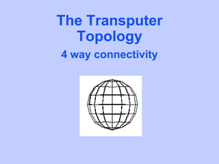
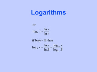
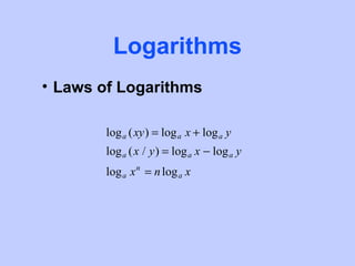
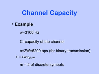
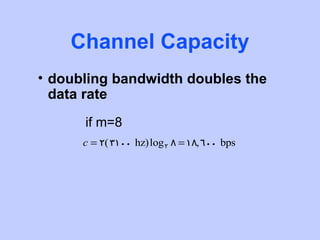
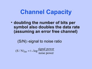
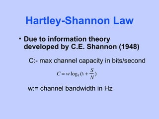
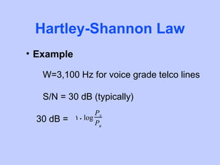
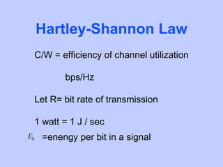
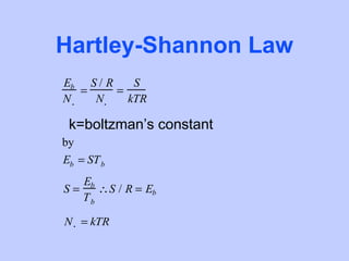
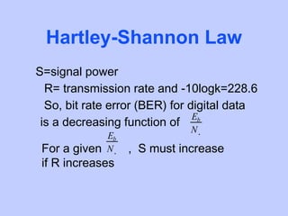
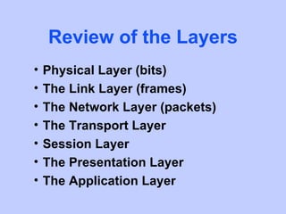
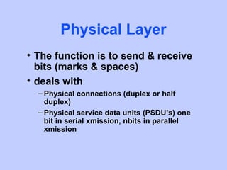
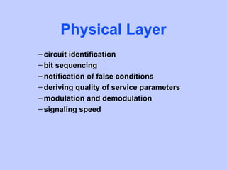
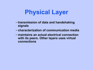
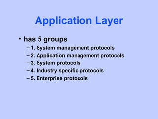
SlideShare a Scribd company logo
NETWORKS
• Covering
  – High speed switching fabrics
  – Twisted pair
  – Mediums
  – Fiber optics
  – Radio
  – Ethernet Coax
NETWORKS
– Logarithms
– Channel capacity
– Hartley-Shannon Law
– Review of the Layers
– Things you need to get started on a LAN
High Speed Switching
       Fabrics
• Aside from the Bus topologies,
  there are many others, with higher
  throughput, like
• ring
• Transputer Topology
• Torus Topology
• Cray T3D
The Transputer
  Topology
4 way connectivity
The Torus Topology
  4 way connectivity
Torus Topology
 5 way connectivity
Cray T3D, Torus
   Topology
 6 way connectivity
Diagram of a typical packet radio setup


                           TNC
Mac
          ASYNC             SYNC              Modem   Radio
          Serial            Serial


                CPU
                Memory


         We left out the redundant curcuitry in the
         gray box to make poor mans packet
Twisted Pair
• Typically a balanced digital line
• 2 conductor insulated wire
• Twisting the wire minimizes the
  electromagnetic interference
• A primary medium for voice traffic
• used as serial cable to hookup
  networks
Twisted Pair
• The repeat coil (transformer) or
  Op-Amp can be used

               S+I
   S
                      +   S+I-(-S+I)=2S
                      -
   -S
               -S+I

        I
Twisted Pair
• In telephone modem terms this is
  known as a DAA (Data Access
  Arrangement).
Mediums
• UTP (unshielded twisted pair)
  – typical voice line
  – Generally good for star LAN short haul 10
    Mbps
• STP (shielded twisted pair)
  – level 5 data grade (100 Mbps)
• RS-422
  – balanced serial data communications
• RS-232
  – unbalanced serial data communications
Mediums
• Coax
  – CATV (community antenna TV)
  – telephone long line via FDM carries 10,000
    voices
  – LAN-WAN
  – cable TV
Mediums
• Fiber Optics
  – use total internal reflection
  – This occurs in a transparent medium
    whose index of refraction is higher that
    surrounding medium
  – optic fiber is a wave guide in the
    10 raised 14 to 10 raised 15 hz range
Fiber Optics
• multimode
  – different rays have different path lengths,
    loss occurs
• multimode-graded index
  – variable core index, focuses rays more
    efficiently that multimode
• single mode
  – only the axial ray passes, most efficient.
Fiber Optics
• LED (light emmiting diode)
  – inexpensive
• ILD (injection laser diode )
  – more expensive (more efficient and higher
    bandwidth that LED).
• Detectors
  – Photo Diodes
Fiber Optics
• light propagates best at 850, 1300
  and 1500 nm
• 640 nm = wavelength of HE-NE
  red = .64 micro meters
• ultra pure fused silica is best,
  plastic is cheapest and worst
Fiber Optics
– bandwidth - 2 Gbps (typical)
– smaller size and weight than copper
– lower attenuation than coax
– electromagnetically isolated
– greater repeater spacing, 5 Gbs over 111
  km w/o repeater
– phasing out cable.             core, one or more strands


                                     cladding, one for each fiber
                       Jacket
Radio
      • Microwave
         – line-of-sight
         – parabolic dish
d = 7.14 kh = distance to horizon
d in meters
h = height of antenna in meters
k = adjustment factor, microwaves bend with the curature of the earth
Ethernet Coax
• For Ethernet coax
  – ASIC’s which give a digital interface to a
    bus topology LAN
  – For example, the Crystal Semiconductor
    Corporation CS83C92 is a Coaxial
    Transceiver Interface on a chip
Ethernet Coax

             CS83C92
                   TX-
             GND   TX+
             TXO   CD-
             CDS   CD+
             RXI   RX-
                   RX+


  Shi el d
Ethernet Coax
• CS83C92
  – Balanced serial inputs
  – Uses Manchester codes
  – All operations with IEEE 802.3 of the
    10Base5 (Ethernet) and 10Base2
    (Cheapernet) standard
Ethernet Coax
• CS83C92 have
  – equalizers
  – amplifiers
  – idle detectors, receiver squelch circuits
  – collision testers
  – oscillators
  – differential line drivers
  – (with other stuff too!!!)
• A manchester code convert chip
  is also needed
Logarithms
• Log Review


       if x = a y then y = log a x
       so
       if x = 210 then 10 = log 2 x
Logarithms
• For example

       find log 2 4096

               4096 = 2 y
               ln 4096 = y ln 2
                ln 4096
                        = y = 12
                  ln 2
Logarithms
so
          ln x
log 2 x =
          ln 2

if base = B then
          ln x log10 x
log B x =     =
          ln B log10 B
Logarithms
• Laws of Logarithms

        log a (xy) = log a x + log a y
        log a (x / y) = log a x − log a y
        log a x n = n log a x
• Intermodulation noise
  – results when signals at different
    frequencies share the same transmission
    medium
• the effect is to create harmonic
  interface at
          f 1 + f 2 and / or f 1 − f 2
          f 1 = frequency of signal 1
          f 2 = frequency of signal 2
• cause
  – transmitter, receiver of intervening
    transmission system nonlinearity
• Crosstalk
  – an unwanted coupling between signal
    paths. i.e hearing another conversation on
    the phone
• Cause
  – electrical coupling
• Impluse noise
  – spikes, irregular pulses
• Cause
  – lightning can severely alter data
Channel Capacity
• Channel Capacity
  – transmission data rate of a channel (bps)
• Bandwidth
  – bandwidth of the transmitted signal (Hz)
• Noise
  – average noise over the channel
• Error rate
  – symbol alteration rate. i.e. 1-> 0
Channel Capacity
• if channel is noise free and of
  bandwidth W, then maximum rate
  of signal transmission is 2W
• This is due to intersymbol
  interface
Channel Capacity
• Example
   w=3100 Hz

   C=capacity of the channel

   c=2W=6200 bps (for binary transmission)
 C = 2Wlog 2 m

   m = # of discrete symbols
Channel Capacity
• doubling bandwidth doubles the
  data rate
      if m=8
      c = 2(3100 hz)log 2 8 = 18, 600 bps
Channel Capacity
• doubling the number of bits per
  symbol also doubles the data rate
  (assuming an error free channel)

   (S/N):-signal to noise ratio
                      signal power
  (S / N)dB   = 10log
                      noise power
Hartley-Shannon Law
• Due to information theory
  developed by C.E. Shannon (1948)
  C:- max channel capacity in bits/second
                          S
           C = w log2 (1 + )
                          N

  w:= channel bandwidth in Hz
Hartley-Shannon Law
• Example

   W=3,100 Hz for voice grade telco lines

   S/N = 30 dB (typically)
                   Ps
 30 dB =    10 log
                   Pn
Hartley-Shannon Law
            Ps
    3 = log
            Pn
             Ps
    log10       =3
             Pn
             Ps
    10 3 =      = 1000
             Pn

    C = 3100 log 2 (1 + 1000) = 30,898 bps
Hartley-Shannon Law
• Represents the theoretical
  maximum that can be achieved
• They assume that we have AWGN
  on a channel
Hartley-Shannon Law
     C/W = efficiency of channel utilization

            bps/Hz

     Let R= bit rate of transmission

     1 watt = 1 J / sec
Eb    =enengy per bit in a signal
Hartley-Shannon Law
  S = signal power (watts)
T b = the time required to send a bit
    1
R=
   Tb
Eb = ST b

Eb
   = energy per noise power density per hertz
N0
Hartley-Shannon Law
Eb S / R    S
   =     =
N0   N0    kTR

 k=boltzman’s constant
by
Eb = ST b
   Eb
S=    ∴S / R = Eb
   Tb

N0 = kTR
Hartley-Shannon Law
 assuming R=W=bandwidth in Hz
 In Decibel Notation:
Eb
   = S −10 log R + 228. 6dbW − 10 logT
N0
Hartley-Shannon Law
S=signal power
  R= transmission rate and -10logk=228.6
  So, bit rate error (BER) for digital data
                                Eb
 is a decreasing function of
                              N0
             Eb
 For a given N0   , S must increase
 if R increases
Hartley-Shannon Law
• Example
 For binary phase-shift keying
 Eb
      =8.4 dB is needed for a bit error rate
 N0
      of 10 −4

    let T= k = noise temperature = C,
    R=2400 bps & Pe = 10 −4 = BER
Hartley-Shannon Law
• Find S
        Eb
 −S = −    −10 log R + 228. 6dbW − 10log T
        N0

 −S = −8. 4 − 10 log2400 + 228.6dbW −10 log 290

  S=-161.8 dbw
ADC’s
• typically are related at a
  convention rate, the number of
  bits (n) and an accuracy (+- flsb)
• for example
  – an 8 bit adc may be related to +- 1/2 lsb
• In general an n bit ADC is related
  to +- 1/2 lsb
ADC’s
• The SNR in (dB) is therefore
                                    S
             SNRdB = 10 log10
                                    N
  where
              S = 2n
                   1 −n −n −1
              N = 2 =2
                   2
                       2n+1
  SNRdB = 10 log10 2          = (20n +10)log10 2

   about    SNRdB = 6n + 3
Review of the Layers
•   Physical Layer (bits)
•   The Link Layer (frames)
•   The Network Layer (packets)
•   The Transport Layer
•   Session Layer
•   The Presentation Layer
•   The Application Layer
Physical Layer
• The function is to send & receive
  bits (marks & spaces)
• deals with
  – Physical connections (duplex or half
    duplex)
  – Physical service data units (PSDU’s) one
    bit in serial xmission, nbits in parallel
    xmission
Physical Layer
– circuit identification
– bit sequencing
– notification of false conditions
– deriving quality of service parameters
– modulation and demodulation
– signaling speed
Physical Layer
– transmission of data and handshaking
  signals
– characterization of communication media
– maintains an actual electrical connection
  with its peers. Other layers uses virtual
  connections
The Link Layer
• The Link Layer of data link control
  arranges the bits into frames
• Most common protocol is ISO
  high-level Data Link Control
  Procedures (ISO 3309)
The Link Layer
• This layer
  – Establishes and releases one or more link
    connections
  – exchanges data-link service data units
    (DLSDUs)-frames
  – identifies end-points
  – keeps DLSDUs / frames in proper
    sequence
The Link Layer
– notifies the network layer when errors are
  detected
– controls data flow
– selects optional qualityof service
  parameters
The Network Layer
• Arranges data into packets
  – Adds the network information to the
    frames to form packets
• SLIP
  – Serial Line Internet Protocol is network
    layer protocol
  – uses the EIA-232 Physical layer
  – Internet protocol is a network layer
    protocol
The Network Layer
– keep track of the network node address
  while routing outgoing packets and
  recognizing packets that are intended for
  the local node
The Network Layer
• ARP
 – Address Resolution Protocol provides
   addresses form required by IP
 – User may specify the datagram route
 – APR will stay aware of manually generated
   routing tables for the datagram routing
   function
The Network Layer

•in CCITT x.25 protocol the network layer
 is called the packet layer.
The Network Layer
• The function provided by the
  network layer are
  – network addressing and identifiers
  – network connections and release
  – transmission of network service data units
    NSDU’s (packets)
  – quality of service parameters
The Network Layer
– notifies the transport layer of errors
– flow control
– expedited service network
– may provide sequenced delivery
The Network Layer
• Two types of network layer
  protocols
  – connection oriented
  – connectionless
Connection Protocol
• set up a virtual circuit (VC)
  between two end points
• Advantage is that since each
  packet does not contain complete
  addressing information, the
  overhead is lower
Connectionless
         Protocol
• Uses a datagram (DG) which
  contains complete addressing
  information in each packet so that
  it can use any variable route
  through the network
Connectionless
         Protocol
• The advantage is that packets
  may freely choose the best
  available routes for the transfer
  rather than being stuck on a VC
  with variable quality
The Transport Layer
• uses transport protocol data units
  (TPDU)
• TPDU = packets + transport layer
  data
• TCP = transmission control
  protocol
The Transport Layer
• This layer ensures that
  – all data send is received completely
  – is sequenced
  – transmission of TPDU messages
  – multiplexing and demultiplexing to share a
    net connection between two or more Xport
    connections
The Transport Layer
– error detection
– error recovery
– connection establishment
– data xfer
– release of connections
The Transport Layer
• CCITT transport protocol in X.224
  says there are 5 classes of
  transport classes
  – 0. simple class
  – 1. error recovery
  – 2. multiplexing
  – 3. error recovery and multiplexing
  – 4. error detection and recovery class
The Transport Layer
• The amount of work done is
  dependent on the protocol (VC or
  datagram) used at the network
  layer
The Transport Layer
• Datagrams may arrive out of
  sequence, in a connectionless
  net, and buffers may be needed to
  resequence
• connection nets allow a leaner
  transport layer
Session Layer
• Organizes data into SPDU
  (session protocol data units)
Session Layer
• This layer does
  – dialog management
  – Data flow control
  – mapping address with name (domain name
    service)
  – graceful or abrupt disconnection
  – buffering data until delivery time
Session Layer
• has phases of service
  – connection establishment
  – data xfer
  – connection release
Presentation Layer
• responsible for the terminal
  management
• Performs
  – transfer of syntax for character sets, text
    strings data display format, graphics file
    organization and data types
Presentation Layer
– data encoding, decoding and compacting
– interpret character sets ( i.e. ASCII)
– code conversion
Application Layer
• The only layer which does not
  interface with a higher one
• It does
  – log in identification of communication
    partners
  – password checking and authority to
    communicate
Application Layer
– determine adequacy of resources
– determine acceptable quality of service
– synchronization of application programs
– selecting the dialog procedures
– agreement on error-recovery responsibility
– procedures for control of data integrity
– identifying data syntax constraints
Application Layer
• has 5 groups
  – 1. System management protocols
  – 2. Application management protocols
  – 3. System protocols
  – 4. Industry specific protocols
  – 5. Enterprise protocols
Things you need to get
   started on a LAN
• IP ADDRESS
 – this a 32 bit number issued by your local IP
   coordinator
 – it is expressed as 4 numbers separated by
   periods
 – looks like 44.112.0.200.
Things you need to get
   started on a LAN
• HOST TABLE
 – A file that list all the folks around you that
   also have IP addresses
 – It must have your IP address and
   hostname (call sign) at least
Things you need to get
   started on a LAN
• HOST TABLE
 – you can get this from your coordinator
 – It looks like this
     44.112.0.1 unix.n3cv1
     44.112.0.2 w3vc
     44.112.0.3 darth.wa3yoa

More Related Content

What's hot

Modulation of digital and analog data
Modulation of digital and analog dataModulation of digital and analog data
Modulation of digital and analog data
Puspa Dhamayanti
 
Lect2 up390 (100329)
Lect2 up390 (100329)Lect2 up390 (100329)
Lect2 up390 (100329)
aicdesign
 
Fundamentals of Passive and Active Sonar Technical Training Short Course Sampler
Fundamentals of Passive and Active Sonar Technical Training Short Course SamplerFundamentals of Passive and Active Sonar Technical Training Short Course Sampler
Fundamentals of Passive and Active Sonar Technical Training Short Course Sampler
Jim Jenkins
 
3. digital transmission fundamentals
3. digital transmission fundamentals3. digital transmission fundamentals
3. digital transmission fundamentals
Rovin Valencia
 
Analog Transmission
Analog TransmissionAnalog Transmission
Analog Transmission
Shiraz316
 
Operating System Concepts - Ch05
Operating System Concepts - Ch05Operating System Concepts - Ch05
Operating System Concepts - Ch05
Wayne Jones Jnr
 
Ch 03
Ch 03Ch 03
Baud rate is the number of change in signal
Baud rate is the number of change in signalBaud rate is the number of change in signal
Baud rate is the number of change in signal
Abhishek Pathak
 
Digital Communication 2
Digital Communication 2Digital Communication 2
Digital Communication 2
admercano101
 
Ncc2004 ofdm tutorial part ii-apal
Ncc2004 ofdm tutorial   part ii-apalNcc2004 ofdm tutorial   part ii-apal
Ncc2004 ofdm tutorial part ii-apal
Arpan Pal
 
PresentationSAR
PresentationSARPresentationSAR
PresentationSAR
Rohollah Javaheri
 
Noise Performance of CW system
Noise Performance of CW systemNoise Performance of CW system
Noise Performance of CW system
Dr Naim R Kidwai
 
Chapter 3 - Data and Signals
Chapter 3 - Data and SignalsChapter 3 - Data and Signals
Chapter 3 - Data and Signals
Wayne Jones Jnr
 
Chapter 4 - Digital Transmission
Chapter 4 - Digital TransmissionChapter 4 - Digital Transmission
Chapter 4 - Digital Transmission
Wayne Jones Jnr
 
Spacecraft RF Communications Course Sampler
Spacecraft RF Communications Course SamplerSpacecraft RF Communications Course Sampler
Spacecraft RF Communications Course Sampler
Jim Jenkins
 
Chap 5
Chap 5Chap 5
Chap 5
Tanuj Patel
 
Chap4 d t-d conversion
Chap4 d t-d conversionChap4 d t-d conversion
Chap4 d t-d conversion
arslan_akbar90
 
Chap 3 data and signals
Chap 3 data and signalsChap 3 data and signals
Chap 3 data and signals
Mukesh Tekwani
 
A System's View of Metro and Regional Optical Networks
A System's View of Metro and Regional Optical NetworksA System's View of Metro and Regional Optical Networks
A System's View of Metro and Regional Optical Networks
Cedric Lam
 
Satellite communications by dennis roddy (4th edition)
Satellite communications by dennis roddy (4th edition)Satellite communications by dennis roddy (4th edition)
Satellite communications by dennis roddy (4th edition)
Adam Năm
 

What's hot (20)

Modulation of digital and analog data
Modulation of digital and analog dataModulation of digital and analog data
Modulation of digital and analog data
 
Lect2 up390 (100329)
Lect2 up390 (100329)Lect2 up390 (100329)
Lect2 up390 (100329)
 
Fundamentals of Passive and Active Sonar Technical Training Short Course Sampler
Fundamentals of Passive and Active Sonar Technical Training Short Course SamplerFundamentals of Passive and Active Sonar Technical Training Short Course Sampler
Fundamentals of Passive and Active Sonar Technical Training Short Course Sampler
 
3. digital transmission fundamentals
3. digital transmission fundamentals3. digital transmission fundamentals
3. digital transmission fundamentals
 
Analog Transmission
Analog TransmissionAnalog Transmission
Analog Transmission
 
Operating System Concepts - Ch05
Operating System Concepts - Ch05Operating System Concepts - Ch05
Operating System Concepts - Ch05
 
Ch 03
Ch 03Ch 03
Ch 03
 
Baud rate is the number of change in signal
Baud rate is the number of change in signalBaud rate is the number of change in signal
Baud rate is the number of change in signal
 
Digital Communication 2
Digital Communication 2Digital Communication 2
Digital Communication 2
 
Ncc2004 ofdm tutorial part ii-apal
Ncc2004 ofdm tutorial   part ii-apalNcc2004 ofdm tutorial   part ii-apal
Ncc2004 ofdm tutorial part ii-apal
 
PresentationSAR
PresentationSARPresentationSAR
PresentationSAR
 
Noise Performance of CW system
Noise Performance of CW systemNoise Performance of CW system
Noise Performance of CW system
 
Chapter 3 - Data and Signals
Chapter 3 - Data and SignalsChapter 3 - Data and Signals
Chapter 3 - Data and Signals
 
Chapter 4 - Digital Transmission
Chapter 4 - Digital TransmissionChapter 4 - Digital Transmission
Chapter 4 - Digital Transmission
 
Spacecraft RF Communications Course Sampler
Spacecraft RF Communications Course SamplerSpacecraft RF Communications Course Sampler
Spacecraft RF Communications Course Sampler
 
Chap 5
Chap 5Chap 5
Chap 5
 
Chap4 d t-d conversion
Chap4 d t-d conversionChap4 d t-d conversion
Chap4 d t-d conversion
 
Chap 3 data and signals
Chap 3 data and signalsChap 3 data and signals
Chap 3 data and signals
 
A System's View of Metro and Regional Optical Networks
A System's View of Metro and Regional Optical NetworksA System's View of Metro and Regional Optical Networks
A System's View of Metro and Regional Optical Networks
 
Satellite communications by dennis roddy (4th edition)
Satellite communications by dennis roddy (4th edition)Satellite communications by dennis roddy (4th edition)
Satellite communications by dennis roddy (4th edition)
 

Viewers also liked

2014 01-29 commercializing your idea iact jan 2014
2014 01-29 commercializing your idea iact jan 20142014 01-29 commercializing your idea iact jan 2014
2014 01-29 commercializing your idea iact jan 2014
douglaslyon
 
2205925 frank morse
2205925 frank morse2205925 frank morse
2205925 frank morse
douglaslyon
 
Freshman orientation4
Freshman orientation4Freshman orientation4
Freshman orientation4
douglaslyon
 
063015 iact presentation-1
063015 iact presentation-1063015 iact presentation-1
063015 iact presentation-1
douglaslyon
 
Class2 13 14_g_hz_differential_signaling
Class2 13 14_g_hz_differential_signalingClass2 13 14_g_hz_differential_signaling
Class2 13 14_g_hz_differential_signaling
douglaslyon
 
063015 iact presentation
063015 iact presentation063015 iact presentation
063015 iact presentation
douglaslyon
 
Search bp oct11_2012
Search bp oct11_2012Search bp oct11_2012
Search bp oct11_2012
douglaslyon
 
Ch9
Ch9Ch9
Lifting 1
Lifting 1Lifting 1
Lifting 1
douglaslyon
 
Chapter 2
Chapter 2Chapter 2
Chapter 2
douglaslyon
 
Asee05
Asee05Asee05
Asee05
douglaslyon
 
Ch9
Ch9Ch9
2010 Developing high quality online doctoral programs2
2010 Developing high quality online doctoral programs22010 Developing high quality online doctoral programs2
2010 Developing high quality online doctoral programs2
WCET
 
2010 Process, Collaboration, and Social Media
2010 Process, Collaboration, and Social Media2010 Process, Collaboration, and Social Media
2010 Process, Collaboration, and Social Media
WCET
 
2011Howell Smackdown 2.0
2011Howell Smackdown 2.02011Howell Smackdown 2.0
2011Howell Smackdown 2.0
WCET
 
Success of success_coaching
Success of success_coachingSuccess of success_coaching
Success of success_coaching
WCET
 
2010 Copyright Fair Use Resources
2010 Copyright Fair Use Resources2010 Copyright Fair Use Resources
2010 Copyright Fair Use Resources
WCET
 
2011Online Higher Ed, Positioning Community Colleges
2011Online Higher Ed, Positioning Community Colleges2011Online Higher Ed, Positioning Community Colleges
2011Online Higher Ed, Positioning Community Colleges
WCET
 
Collaborating for student_success
Collaborating for student_successCollaborating for student_success
Collaborating for student_success
WCET
 

Viewers also liked (20)

2014 01-29 commercializing your idea iact jan 2014
2014 01-29 commercializing your idea iact jan 20142014 01-29 commercializing your idea iact jan 2014
2014 01-29 commercializing your idea iact jan 2014
 
2205925 frank morse
2205925 frank morse2205925 frank morse
2205925 frank morse
 
Freshman orientation4
Freshman orientation4Freshman orientation4
Freshman orientation4
 
063015 iact presentation-1
063015 iact presentation-1063015 iact presentation-1
063015 iact presentation-1
 
Class2 13 14_g_hz_differential_signaling
Class2 13 14_g_hz_differential_signalingClass2 13 14_g_hz_differential_signaling
Class2 13 14_g_hz_differential_signaling
 
063015 iact presentation
063015 iact presentation063015 iact presentation
063015 iact presentation
 
Search bp oct11_2012
Search bp oct11_2012Search bp oct11_2012
Search bp oct11_2012
 
Ch9
Ch9Ch9
Ch9
 
Lifting 1
Lifting 1Lifting 1
Lifting 1
 
Chapter 2
Chapter 2Chapter 2
Chapter 2
 
Asee05
Asee05Asee05
Asee05
 
Ch9
Ch9Ch9
Ch9
 
2010 Developing high quality online doctoral programs2
2010 Developing high quality online doctoral programs22010 Developing high quality online doctoral programs2
2010 Developing high quality online doctoral programs2
 
2010 Process, Collaboration, and Social Media
2010 Process, Collaboration, and Social Media2010 Process, Collaboration, and Social Media
2010 Process, Collaboration, and Social Media
 
2011Howell Smackdown 2.0
2011Howell Smackdown 2.02011Howell Smackdown 2.0
2011Howell Smackdown 2.0
 
Success of success_coaching
Success of success_coachingSuccess of success_coaching
Success of success_coaching
 
2010 Copyright Fair Use Resources
2010 Copyright Fair Use Resources2010 Copyright Fair Use Resources
2010 Copyright Fair Use Resources
 
2011Online Higher Ed, Positioning Community Colleges
2011Online Higher Ed, Positioning Community Colleges2011Online Higher Ed, Positioning Community Colleges
2011Online Higher Ed, Positioning Community Colleges
 
Collaborating for student_success
Collaborating for student_successCollaborating for student_success
Collaborating for student_success
 
Ozono
OzonoOzono
Ozono
 

Similar to Logsv2

Lec2WirelessChannelandRadioPropagation.pdf
Lec2WirelessChannelandRadioPropagation.pdfLec2WirelessChannelandRadioPropagation.pdf
Lec2WirelessChannelandRadioPropagation.pdf
PatrickMumba7
 
Chapter2 The Physical Layer(1).pptx
Chapter2 The Physical Layer(1).pptxChapter2 The Physical Layer(1).pptx
Chapter2 The Physical Layer(1).pptx
huanyuzhang5
 
IMT Advanced
IMT AdvancedIMT Advanced
Computer Networks 7.Physical LayerComputer Networks 7.Physical Layer
Computer Networks 7.Physical LayerComputer Networks 7.Physical LayerComputer Networks 7.Physical LayerComputer Networks 7.Physical Layer
Computer Networks 7.Physical LayerComputer Networks 7.Physical Layer
jeronimored
 
Lecture intro to_wcdma
Lecture intro to_wcdmaLecture intro to_wcdma
Lecture intro to_wcdma
Gurpreet Singh
 
Lecture set 2
Lecture set 2Lecture set 2
Lecture set 2
Gopi Saiteja
 
Sampling Theorem, Quantization Noise and its types, PCM, Channel Capacity, Ny...
Sampling Theorem, Quantization Noise and its types, PCM, Channel Capacity, Ny...Sampling Theorem, Quantization Noise and its types, PCM, Channel Capacity, Ny...
Sampling Theorem, Quantization Noise and its types, PCM, Channel Capacity, Ny...
Waqas Afzal
 
Link power and rise time budget analysis
Link power and rise time budget analysisLink power and rise time budget analysis
Link power and rise time budget analysis
CKSunith1
 
week1.ppt12345667777777777777777777777777
week1.ppt12345667777777777777777777777777week1.ppt12345667777777777777777777777777
week1.ppt12345667777777777777777777777777
KiranG731731
 
ofdm
ofdmofdm
1999 si pi_dws_training_course
1999 si pi_dws_training_course1999 si pi_dws_training_course
1999 si pi_dws_training_course
Piero Belforte
 
Channel impairments
Channel impairmentsChannel impairments
Channel impairments
Muhammad Uzair Rasheed
 
log periodic antenna
log periodic antennalog periodic antenna
log periodic antenna
prashant kumar
 
synthetic aperture radar
synthetic aperture radarsynthetic aperture radar
synthetic aperture radar
Amit Rastogi
 
Light wave-system-3855513
Light wave-system-3855513Light wave-system-3855513
Light wave-system-3855513
Pooja Shukla
 
dab_1.pdf
dab_1.pdfdab_1.pdf
dab_1.pdf
ssusera6186a1
 
Tele3113 wk10tue
Tele3113 wk10tueTele3113 wk10tue
Tele3113 wk10tue
Vin Voro
 
Modulation technology
Modulation technologyModulation technology
Modulation technology
Pei-Che Chang
 
Chapter 2.1.pptx
Chapter 2.1.pptxChapter 2.1.pptx
Chapter 2.1.pptx
Tekle12
 
Chapter 2.1.pptx
Chapter 2.1.pptxChapter 2.1.pptx
Chapter 2.1.pptx
Tekle12
 

Similar to Logsv2 (20)

Lec2WirelessChannelandRadioPropagation.pdf
Lec2WirelessChannelandRadioPropagation.pdfLec2WirelessChannelandRadioPropagation.pdf
Lec2WirelessChannelandRadioPropagation.pdf
 
Chapter2 The Physical Layer(1).pptx
Chapter2 The Physical Layer(1).pptxChapter2 The Physical Layer(1).pptx
Chapter2 The Physical Layer(1).pptx
 
IMT Advanced
IMT AdvancedIMT Advanced
IMT Advanced
 
Computer Networks 7.Physical LayerComputer Networks 7.Physical Layer
Computer Networks 7.Physical LayerComputer Networks 7.Physical LayerComputer Networks 7.Physical LayerComputer Networks 7.Physical Layer
Computer Networks 7.Physical LayerComputer Networks 7.Physical Layer
 
Lecture intro to_wcdma
Lecture intro to_wcdmaLecture intro to_wcdma
Lecture intro to_wcdma
 
Lecture set 2
Lecture set 2Lecture set 2
Lecture set 2
 
Sampling Theorem, Quantization Noise and its types, PCM, Channel Capacity, Ny...
Sampling Theorem, Quantization Noise and its types, PCM, Channel Capacity, Ny...Sampling Theorem, Quantization Noise and its types, PCM, Channel Capacity, Ny...
Sampling Theorem, Quantization Noise and its types, PCM, Channel Capacity, Ny...
 
Link power and rise time budget analysis
Link power and rise time budget analysisLink power and rise time budget analysis
Link power and rise time budget analysis
 
week1.ppt12345667777777777777777777777777
week1.ppt12345667777777777777777777777777week1.ppt12345667777777777777777777777777
week1.ppt12345667777777777777777777777777
 
ofdm
ofdmofdm
ofdm
 
1999 si pi_dws_training_course
1999 si pi_dws_training_course1999 si pi_dws_training_course
1999 si pi_dws_training_course
 
Channel impairments
Channel impairmentsChannel impairments
Channel impairments
 
log periodic antenna
log periodic antennalog periodic antenna
log periodic antenna
 
synthetic aperture radar
synthetic aperture radarsynthetic aperture radar
synthetic aperture radar
 
Light wave-system-3855513
Light wave-system-3855513Light wave-system-3855513
Light wave-system-3855513
 
dab_1.pdf
dab_1.pdfdab_1.pdf
dab_1.pdf
 
Tele3113 wk10tue
Tele3113 wk10tueTele3113 wk10tue
Tele3113 wk10tue
 
Modulation technology
Modulation technologyModulation technology
Modulation technology
 
Chapter 2.1.pptx
Chapter 2.1.pptxChapter 2.1.pptx
Chapter 2.1.pptx
 
Chapter 2.1.pptx
Chapter 2.1.pptxChapter 2.1.pptx
Chapter 2.1.pptx
 

Logsv2

  • 1. NETWORKS • Covering – High speed switching fabrics – Twisted pair – Mediums – Fiber optics – Radio – Ethernet Coax
  • 2. NETWORKS – Logarithms – Channel capacity – Hartley-Shannon Law – Review of the Layers – Things you need to get started on a LAN
  • 3. High Speed Switching Fabrics • Aside from the Bus topologies, there are many others, with higher throughput, like • ring • Transputer Topology • Torus Topology • Cray T3D
  • 4. The Transputer Topology 4 way connectivity
  • 5. The Torus Topology 4 way connectivity
  • 6. Torus Topology 5 way connectivity
  • 7. Cray T3D, Torus Topology 6 way connectivity
  • 8. Diagram of a typical packet radio setup TNC Mac ASYNC SYNC Modem Radio Serial Serial CPU Memory We left out the redundant curcuitry in the gray box to make poor mans packet
  • 9. Twisted Pair • Typically a balanced digital line • 2 conductor insulated wire • Twisting the wire minimizes the electromagnetic interference • A primary medium for voice traffic • used as serial cable to hookup networks
  • 10. Twisted Pair • The repeat coil (transformer) or Op-Amp can be used S+I S + S+I-(-S+I)=2S - -S -S+I I
  • 11. Twisted Pair • In telephone modem terms this is known as a DAA (Data Access Arrangement).
  • 12. Mediums • UTP (unshielded twisted pair) – typical voice line – Generally good for star LAN short haul 10 Mbps • STP (shielded twisted pair) – level 5 data grade (100 Mbps) • RS-422 – balanced serial data communications • RS-232 – unbalanced serial data communications
  • 13. Mediums • Coax – CATV (community antenna TV) – telephone long line via FDM carries 10,000 voices – LAN-WAN – cable TV
  • 14. Mediums • Fiber Optics – use total internal reflection – This occurs in a transparent medium whose index of refraction is higher that surrounding medium – optic fiber is a wave guide in the 10 raised 14 to 10 raised 15 hz range
  • 15. Fiber Optics • multimode – different rays have different path lengths, loss occurs • multimode-graded index – variable core index, focuses rays more efficiently that multimode • single mode – only the axial ray passes, most efficient.
  • 16. Fiber Optics • LED (light emmiting diode) – inexpensive • ILD (injection laser diode ) – more expensive (more efficient and higher bandwidth that LED). • Detectors – Photo Diodes
  • 17. Fiber Optics • light propagates best at 850, 1300 and 1500 nm • 640 nm = wavelength of HE-NE red = .64 micro meters • ultra pure fused silica is best, plastic is cheapest and worst
  • 18. Fiber Optics – bandwidth - 2 Gbps (typical) – smaller size and weight than copper – lower attenuation than coax – electromagnetically isolated – greater repeater spacing, 5 Gbs over 111 km w/o repeater – phasing out cable. core, one or more strands cladding, one for each fiber Jacket
  • 19. Radio • Microwave – line-of-sight – parabolic dish d = 7.14 kh = distance to horizon d in meters h = height of antenna in meters k = adjustment factor, microwaves bend with the curature of the earth
  • 20. Ethernet Coax • For Ethernet coax – ASIC’s which give a digital interface to a bus topology LAN – For example, the Crystal Semiconductor Corporation CS83C92 is a Coaxial Transceiver Interface on a chip
  • 21. Ethernet Coax CS83C92 TX- GND TX+ TXO CD- CDS CD+ RXI RX- RX+ Shi el d
  • 22. Ethernet Coax • CS83C92 – Balanced serial inputs – Uses Manchester codes – All operations with IEEE 802.3 of the 10Base5 (Ethernet) and 10Base2 (Cheapernet) standard
  • 23. Ethernet Coax • CS83C92 have – equalizers – amplifiers – idle detectors, receiver squelch circuits – collision testers – oscillators – differential line drivers – (with other stuff too!!!) • A manchester code convert chip is also needed
  • 24. Logarithms • Log Review if x = a y then y = log a x so if x = 210 then 10 = log 2 x
  • 25. Logarithms • For example find log 2 4096 4096 = 2 y ln 4096 = y ln 2 ln 4096 = y = 12 ln 2
  • 26. Logarithms so ln x log 2 x = ln 2 if base = B then ln x log10 x log B x = = ln B log10 B
  • 27. Logarithms • Laws of Logarithms log a (xy) = log a x + log a y log a (x / y) = log a x − log a y log a x n = n log a x
  • 28. • Intermodulation noise – results when signals at different frequencies share the same transmission medium
  • 29. • the effect is to create harmonic interface at f 1 + f 2 and / or f 1 − f 2 f 1 = frequency of signal 1 f 2 = frequency of signal 2
  • 30. • cause – transmitter, receiver of intervening transmission system nonlinearity
  • 31. • Crosstalk – an unwanted coupling between signal paths. i.e hearing another conversation on the phone • Cause – electrical coupling
  • 32. • Impluse noise – spikes, irregular pulses • Cause – lightning can severely alter data
  • 33. Channel Capacity • Channel Capacity – transmission data rate of a channel (bps) • Bandwidth – bandwidth of the transmitted signal (Hz) • Noise – average noise over the channel • Error rate – symbol alteration rate. i.e. 1-> 0
  • 34. Channel Capacity • if channel is noise free and of bandwidth W, then maximum rate of signal transmission is 2W • This is due to intersymbol interface
  • 35. Channel Capacity • Example w=3100 Hz C=capacity of the channel c=2W=6200 bps (for binary transmission) C = 2Wlog 2 m m = # of discrete symbols
  • 36. Channel Capacity • doubling bandwidth doubles the data rate if m=8 c = 2(3100 hz)log 2 8 = 18, 600 bps
  • 37. Channel Capacity • doubling the number of bits per symbol also doubles the data rate (assuming an error free channel) (S/N):-signal to noise ratio signal power (S / N)dB = 10log noise power
  • 38. Hartley-Shannon Law • Due to information theory developed by C.E. Shannon (1948) C:- max channel capacity in bits/second S C = w log2 (1 + ) N w:= channel bandwidth in Hz
  • 39. Hartley-Shannon Law • Example W=3,100 Hz for voice grade telco lines S/N = 30 dB (typically) Ps 30 dB = 10 log Pn
  • 40. Hartley-Shannon Law Ps 3 = log Pn Ps log10 =3 Pn Ps 10 3 = = 1000 Pn C = 3100 log 2 (1 + 1000) = 30,898 bps
  • 41. Hartley-Shannon Law • Represents the theoretical maximum that can be achieved • They assume that we have AWGN on a channel
  • 42. Hartley-Shannon Law C/W = efficiency of channel utilization bps/Hz Let R= bit rate of transmission 1 watt = 1 J / sec Eb =enengy per bit in a signal
  • 43. Hartley-Shannon Law S = signal power (watts) T b = the time required to send a bit 1 R= Tb Eb = ST b Eb = energy per noise power density per hertz N0
  • 44. Hartley-Shannon Law Eb S / R S = = N0 N0 kTR k=boltzman’s constant by Eb = ST b Eb S= ∴S / R = Eb Tb N0 = kTR
  • 45. Hartley-Shannon Law assuming R=W=bandwidth in Hz In Decibel Notation: Eb = S −10 log R + 228. 6dbW − 10 logT N0
  • 46. Hartley-Shannon Law S=signal power R= transmission rate and -10logk=228.6 So, bit rate error (BER) for digital data Eb is a decreasing function of N0 Eb For a given N0 , S must increase if R increases
  • 47. Hartley-Shannon Law • Example For binary phase-shift keying Eb =8.4 dB is needed for a bit error rate N0 of 10 −4 let T= k = noise temperature = C, R=2400 bps & Pe = 10 −4 = BER
  • 48. Hartley-Shannon Law • Find S Eb −S = − −10 log R + 228. 6dbW − 10log T N0 −S = −8. 4 − 10 log2400 + 228.6dbW −10 log 290 S=-161.8 dbw
  • 49. ADC’s • typically are related at a convention rate, the number of bits (n) and an accuracy (+- flsb) • for example – an 8 bit adc may be related to +- 1/2 lsb • In general an n bit ADC is related to +- 1/2 lsb
  • 50. ADC’s • The SNR in (dB) is therefore S SNRdB = 10 log10 N where S = 2n 1 −n −n −1 N = 2 =2 2 2n+1 SNRdB = 10 log10 2 = (20n +10)log10 2 about SNRdB = 6n + 3
  • 51. Review of the Layers • Physical Layer (bits) • The Link Layer (frames) • The Network Layer (packets) • The Transport Layer • Session Layer • The Presentation Layer • The Application Layer
  • 52. Physical Layer • The function is to send & receive bits (marks & spaces) • deals with – Physical connections (duplex or half duplex) – Physical service data units (PSDU’s) one bit in serial xmission, nbits in parallel xmission
  • 53. Physical Layer – circuit identification – bit sequencing – notification of false conditions – deriving quality of service parameters – modulation and demodulation – signaling speed
  • 54. Physical Layer – transmission of data and handshaking signals – characterization of communication media – maintains an actual electrical connection with its peers. Other layers uses virtual connections
  • 55. The Link Layer • The Link Layer of data link control arranges the bits into frames • Most common protocol is ISO high-level Data Link Control Procedures (ISO 3309)
  • 56. The Link Layer • This layer – Establishes and releases one or more link connections – exchanges data-link service data units (DLSDUs)-frames – identifies end-points – keeps DLSDUs / frames in proper sequence
  • 57. The Link Layer – notifies the network layer when errors are detected – controls data flow – selects optional qualityof service parameters
  • 58. The Network Layer • Arranges data into packets – Adds the network information to the frames to form packets • SLIP – Serial Line Internet Protocol is network layer protocol – uses the EIA-232 Physical layer – Internet protocol is a network layer protocol
  • 59. The Network Layer – keep track of the network node address while routing outgoing packets and recognizing packets that are intended for the local node
  • 60. The Network Layer • ARP – Address Resolution Protocol provides addresses form required by IP – User may specify the datagram route – APR will stay aware of manually generated routing tables for the datagram routing function
  • 61. The Network Layer •in CCITT x.25 protocol the network layer is called the packet layer.
  • 62. The Network Layer • The function provided by the network layer are – network addressing and identifiers – network connections and release – transmission of network service data units NSDU’s (packets) – quality of service parameters
  • 63. The Network Layer – notifies the transport layer of errors – flow control – expedited service network – may provide sequenced delivery
  • 64. The Network Layer • Two types of network layer protocols – connection oriented – connectionless
  • 65. Connection Protocol • set up a virtual circuit (VC) between two end points • Advantage is that since each packet does not contain complete addressing information, the overhead is lower
  • 66. Connectionless Protocol • Uses a datagram (DG) which contains complete addressing information in each packet so that it can use any variable route through the network
  • 67. Connectionless Protocol • The advantage is that packets may freely choose the best available routes for the transfer rather than being stuck on a VC with variable quality
  • 68. The Transport Layer • uses transport protocol data units (TPDU) • TPDU = packets + transport layer data • TCP = transmission control protocol
  • 69. The Transport Layer • This layer ensures that – all data send is received completely – is sequenced – transmission of TPDU messages – multiplexing and demultiplexing to share a net connection between two or more Xport connections
  • 70. The Transport Layer – error detection – error recovery – connection establishment – data xfer – release of connections
  • 71. The Transport Layer • CCITT transport protocol in X.224 says there are 5 classes of transport classes – 0. simple class – 1. error recovery – 2. multiplexing – 3. error recovery and multiplexing – 4. error detection and recovery class
  • 72. The Transport Layer • The amount of work done is dependent on the protocol (VC or datagram) used at the network layer
  • 73. The Transport Layer • Datagrams may arrive out of sequence, in a connectionless net, and buffers may be needed to resequence • connection nets allow a leaner transport layer
  • 74. Session Layer • Organizes data into SPDU (session protocol data units)
  • 75. Session Layer • This layer does – dialog management – Data flow control – mapping address with name (domain name service) – graceful or abrupt disconnection – buffering data until delivery time
  • 76. Session Layer • has phases of service – connection establishment – data xfer – connection release
  • 77. Presentation Layer • responsible for the terminal management • Performs – transfer of syntax for character sets, text strings data display format, graphics file organization and data types
  • 78. Presentation Layer – data encoding, decoding and compacting – interpret character sets ( i.e. ASCII) – code conversion
  • 79. Application Layer • The only layer which does not interface with a higher one • It does – log in identification of communication partners – password checking and authority to communicate
  • 80. Application Layer – determine adequacy of resources – determine acceptable quality of service – synchronization of application programs – selecting the dialog procedures – agreement on error-recovery responsibility – procedures for control of data integrity – identifying data syntax constraints
  • 81. Application Layer • has 5 groups – 1. System management protocols – 2. Application management protocols – 3. System protocols – 4. Industry specific protocols – 5. Enterprise protocols
  • 82. Things you need to get started on a LAN • IP ADDRESS – this a 32 bit number issued by your local IP coordinator – it is expressed as 4 numbers separated by periods – looks like 44.112.0.200.
  • 83. Things you need to get started on a LAN • HOST TABLE – A file that list all the folks around you that also have IP addresses – It must have your IP address and hostname (call sign) at least
  • 84. Things you need to get started on a LAN • HOST TABLE – you can get this from your coordinator – It looks like this 44.112.0.1 unix.n3cv1 44.112.0.2 w3vc 44.112.0.3 darth.wa3yoa