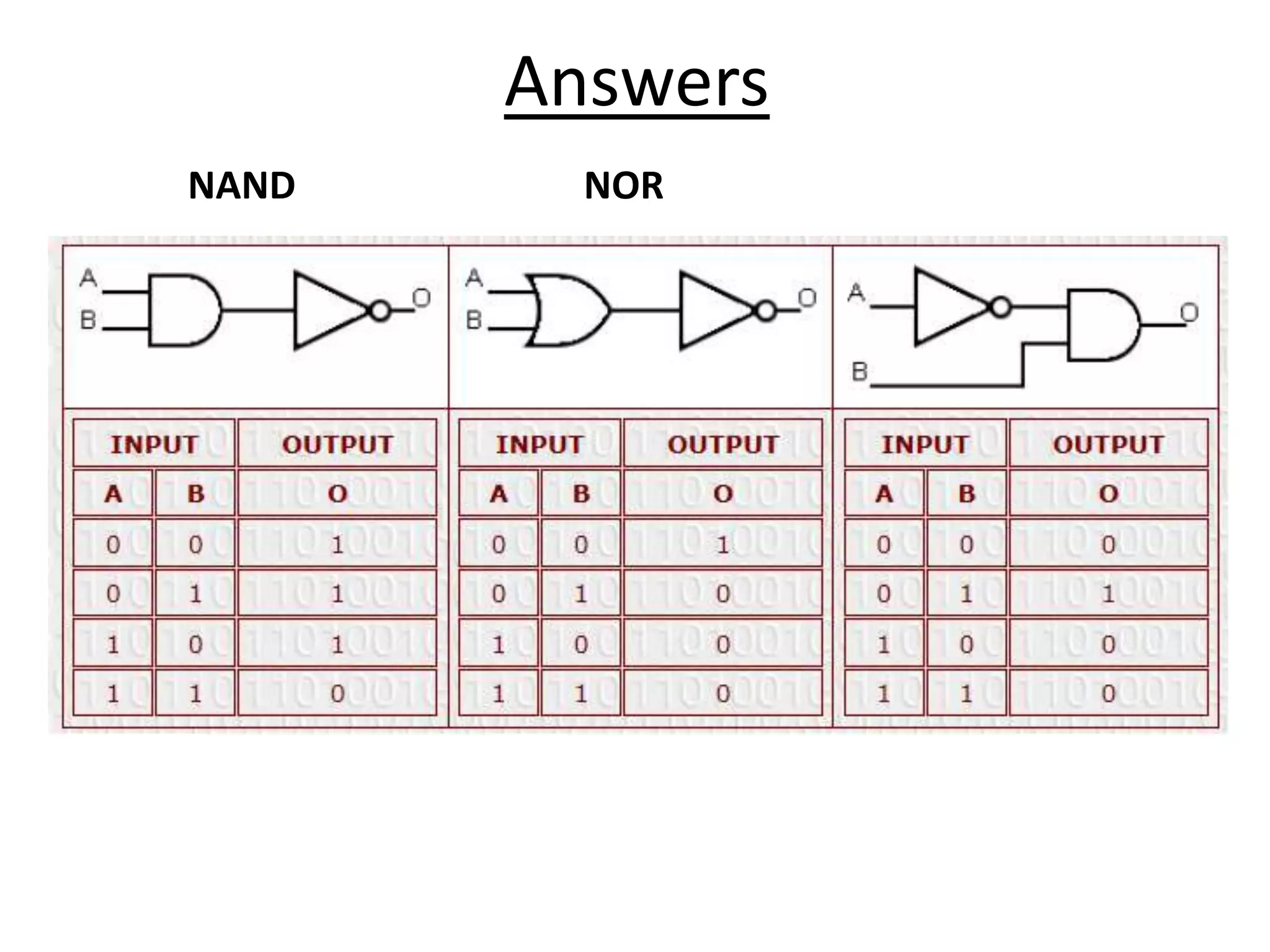
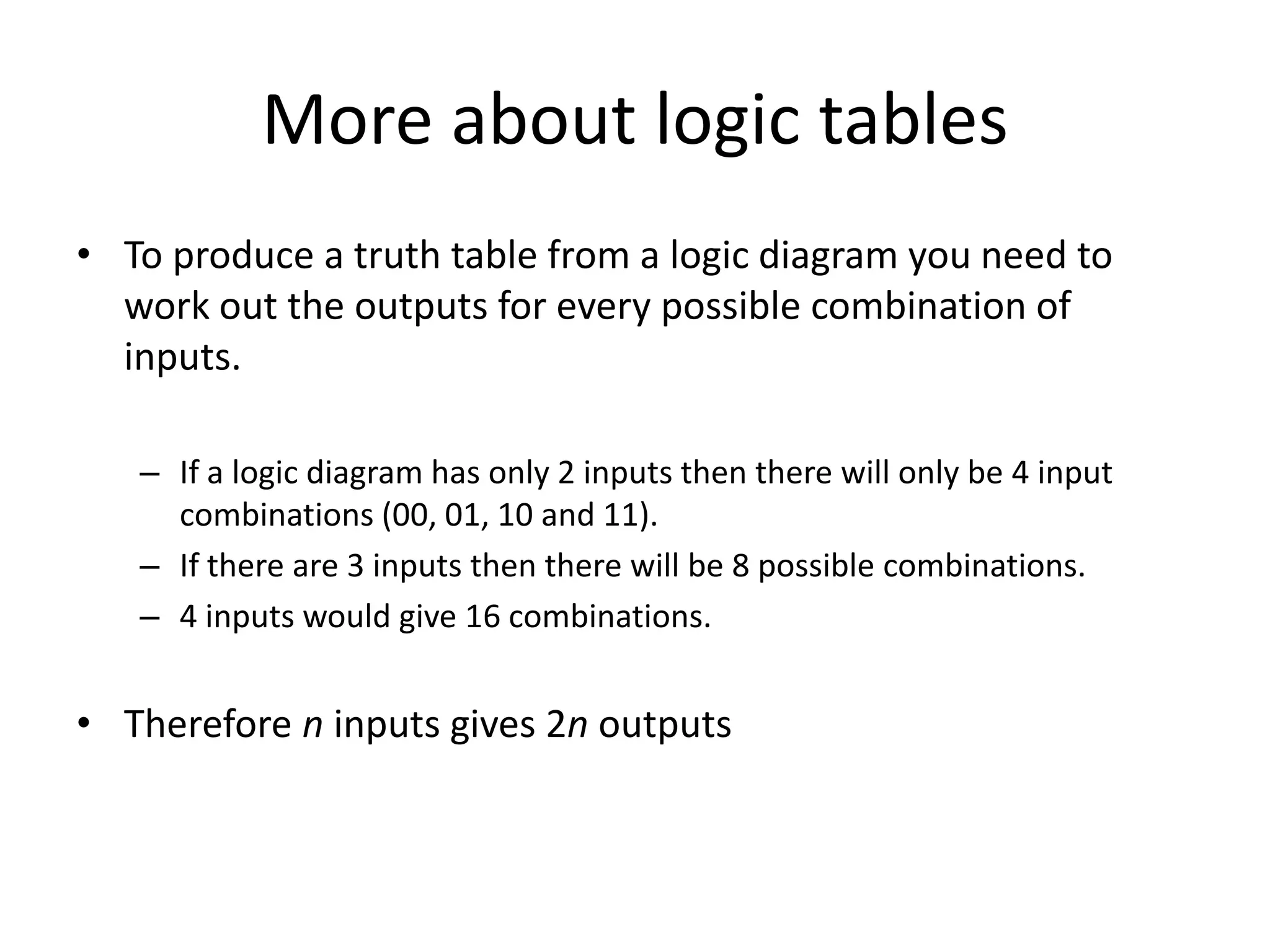
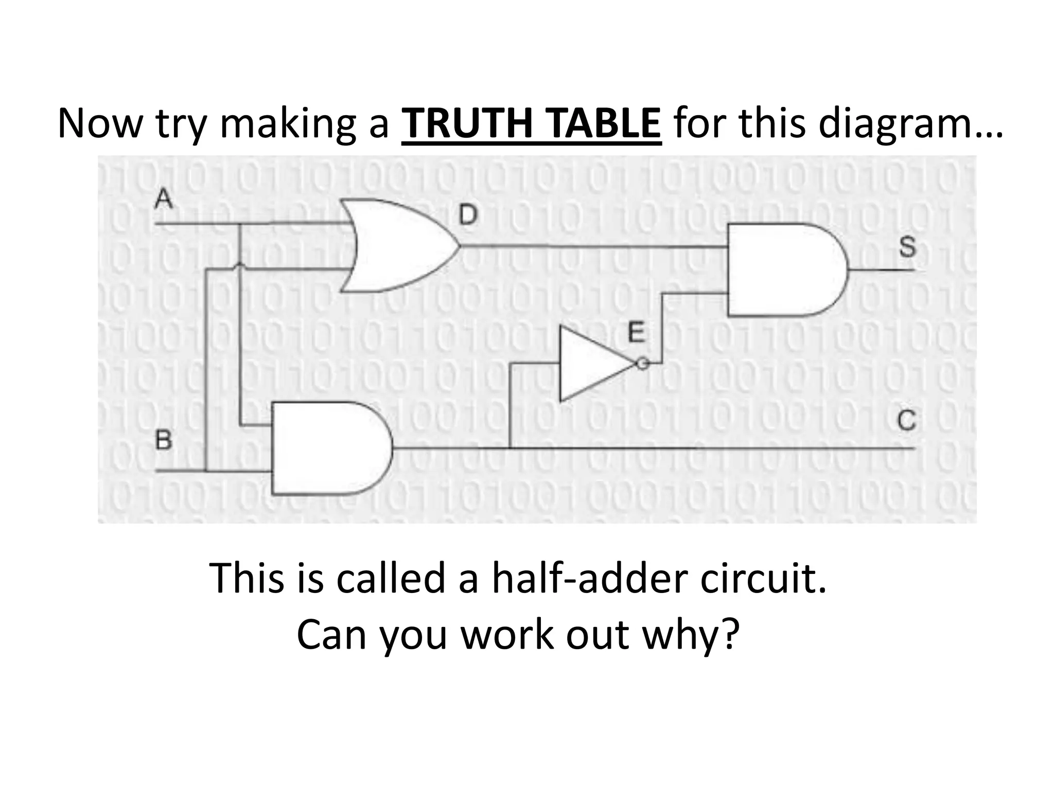
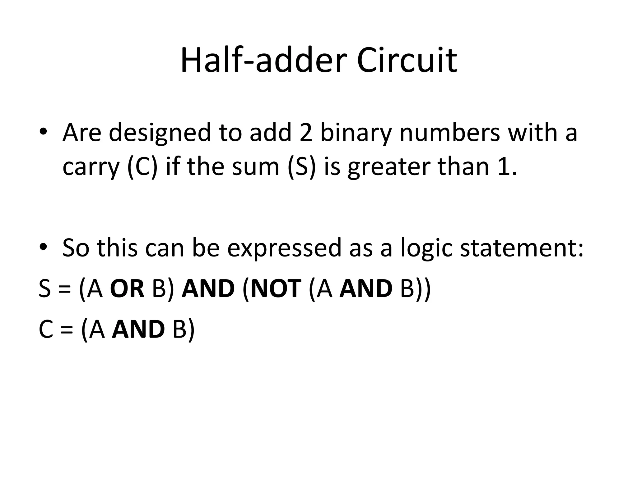
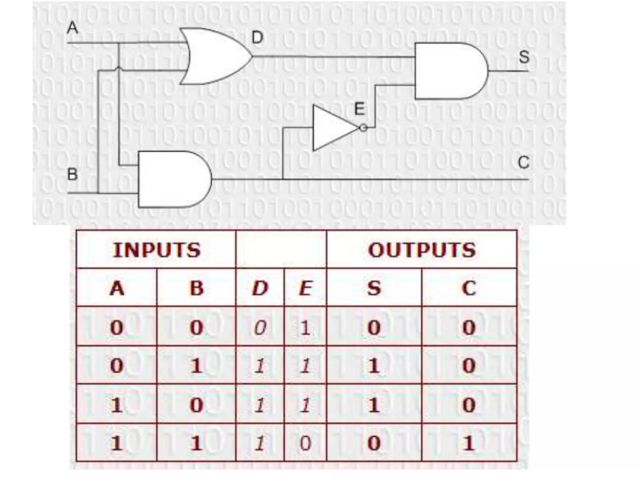
O = NOT (A AND B)   O = NOT (A OR B)   O = (NOT A) AND B


         Make a TRUTH TABLE for each of
            the above logic diagrams
Answers
NAND     NOR
More about logic tables
• To produce a truth table from a logic diagram you need to
  work out the outputs for every possible combination of
  inputs.

   – If a logic diagram has only 2 inputs then there will only be 4 input
     combinations (00, 01, 10 and 11).
   – If there are 3 inputs then there will be 8 possible combinations.
   – 4 inputs would give 16 combinations.


• Therefore n inputs gives 2n outputs
Now try making a TRUTH TABLE for this diagram…


       This is called a half-adder circuit.
            Can you work out why?
Half-adder Circuit
• Are designed to add 2 binary numbers with a
  carry (C) if the sum (S) is greater than 1.

• So this can be expressed as a logic statement:
S = (A OR B) AND (NOT (A AND B))
C = (A AND B)
Logic diagrams starter teacher version

Logic diagrams starter teacher version

  • 1.
    O = NOT(A AND B) O = NOT (A OR B) O = (NOT A) AND B Make a TRUTH TABLE for each of the above logic diagrams
  • 2.
  • 3.
    More about logictables • To produce a truth table from a logic diagram you need to work out the outputs for every possible combination of inputs. – If a logic diagram has only 2 inputs then there will only be 4 input combinations (00, 01, 10 and 11). – If there are 3 inputs then there will be 8 possible combinations. – 4 inputs would give 16 combinations. • Therefore n inputs gives 2n outputs
  • 4.
    Now try makinga TRUTH TABLE for this diagram… This is called a half-adder circuit. Can you work out why?
  • 5.
    Half-adder Circuit • Aredesigned to add 2 binary numbers with a carry (C) if the sum (S) is greater than 1. • So this can be expressed as a logic statement: S = (A OR B) AND (NOT (A AND B)) C = (A AND B)