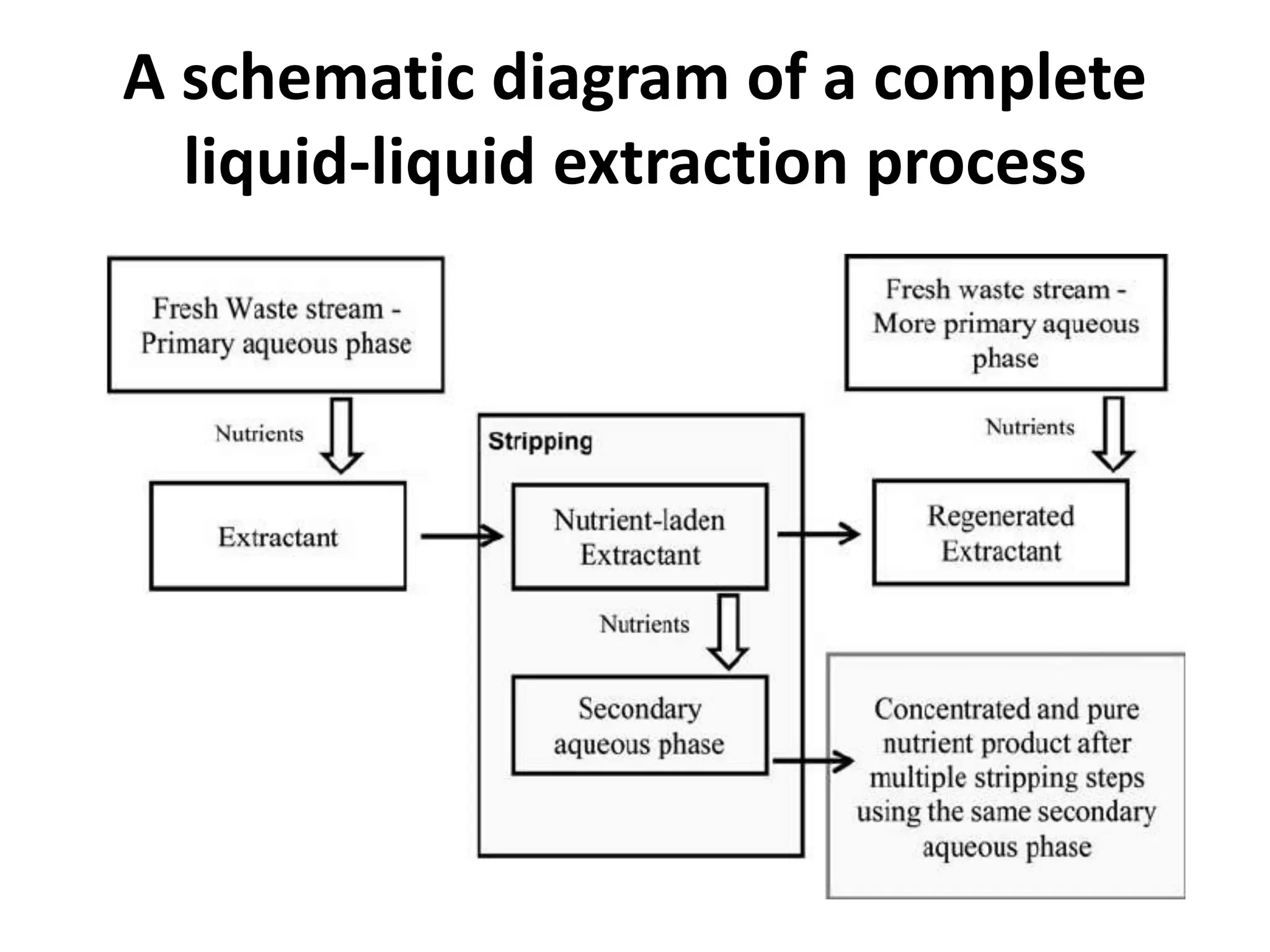
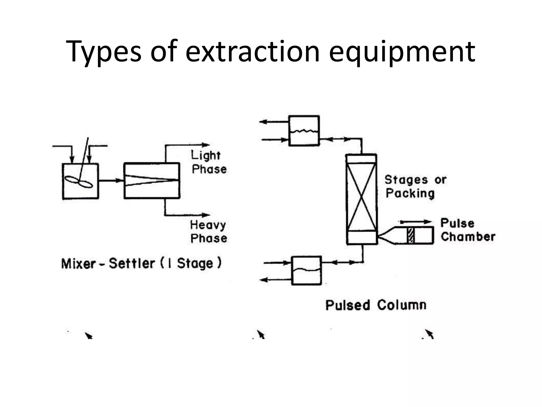
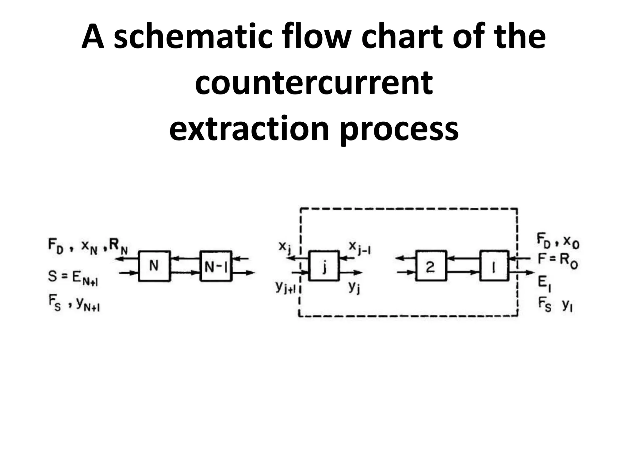
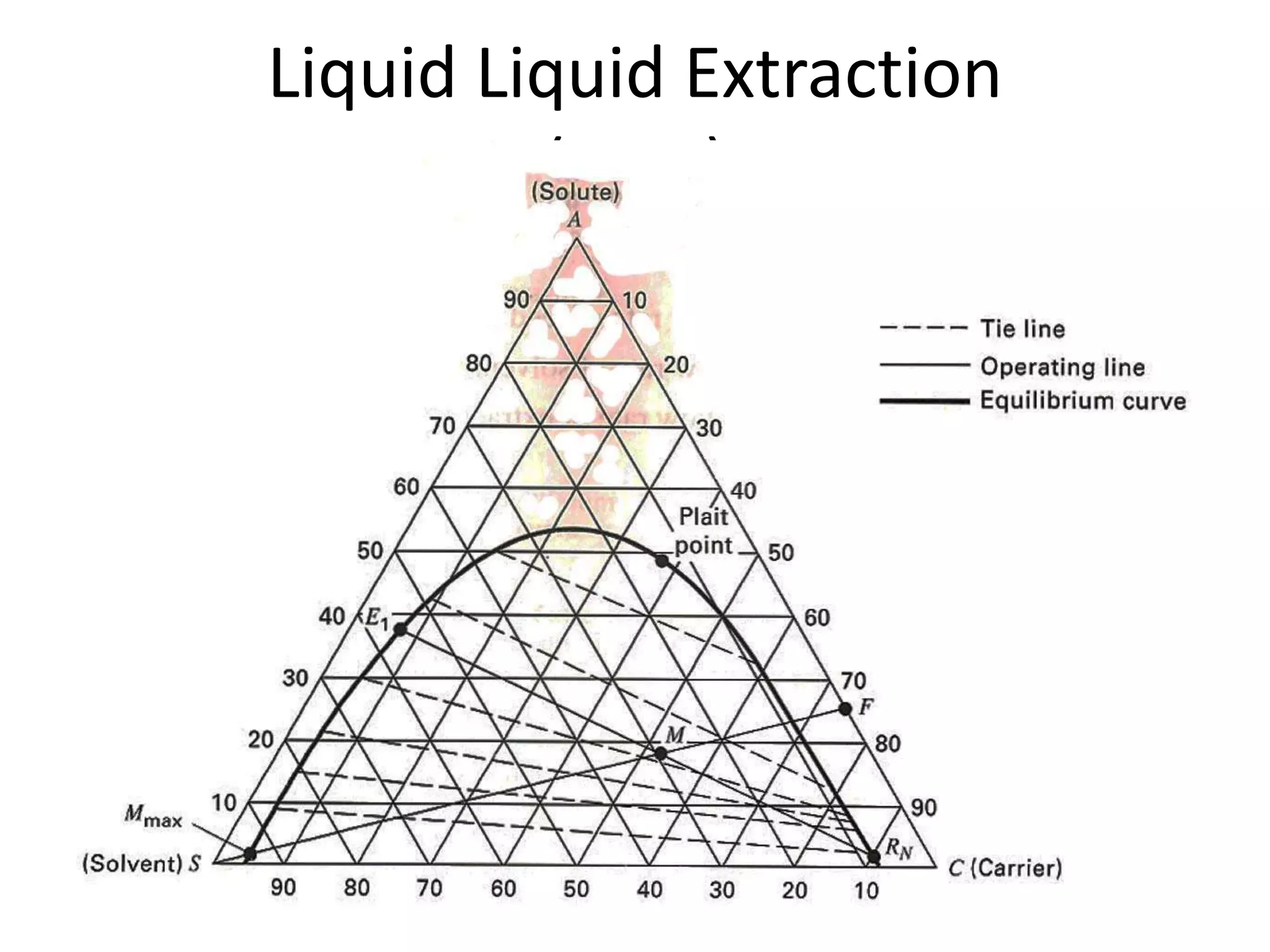
A.D.Patel Institute of
Technology
 Subject :- Food Engineering Operation - II ( 2161403 )
 Topic :- Liquid Liquid Extraction in Food Industry
 Dept. :- Food Processing Technology
 Prepared By :- Jemishkumar Parmar ( 170010114024 )
Akshar Patel ( 170010114026 )
 Submitted To :- Dr.P.M.Ganorkar & Dr.Ksitiz Kumar
Liquid Liquid Extraction
• Extraction is a process where one or more
solutes are removed from one liquid
phase/carrier/diluent by transferring the
solutes to another liquid phase/solvent.
• No vaporisation is needed
• Extraction can be performed at low
temperatures
 In this extraction process, the feed, which contains carrier
and the solute is sent to the extraction unit.
 A solvent is also fed into the extractor, with the purpose
to remove the solute from the carrier.
 The extract phase (or the loaded solvent) is then sent to
the solvent recovery unit, to
 separate the desired solute from the extract phase.
 recover the solvent, which can be reused or recycled to be
used again as the solvent.
Examples of the uses of extraction
are
• The separation of penicillin from the broth
(the liquid phase obtained from biological
processes).
• The separation of aromatic-ring hydrocarbons
(e.g., benzene, toluene) from paraffins using
sulpholane.
A schematic diagram of a complete
liquid-liquid extraction process
• In the extraction process, the feed, which
contains the first solvent (or the diluent) and
the solute is sent to the extraction unit (or the
extractor).
• Another solvent (commonly called the solvent)
is also fed into the extractor, with the purpose
to remove the solute from the diluent.
Continue
• Normally, the diluent + the remaining solute
is called the raffinate phase, while the second
solvent + the solute is called the extract
phase.
• The extract phase (or the loaded solvent) is
then sent to the solvent recovery unit, to :
• Separate the desired solute from the extract
phase.
• recover the second solvent, which can be
reused or recycled to be used again as the
solvent
Types of extraction equipment
A schematic flow chart of the
countercurrent
extraction process
• In this counter-current extraction system, the
raffinate and extract phases are fed into the
system in the opposite directions.
• In above fig. the raffinate phase consisting of
the solute A and the diluent D is fed into the
system from the right hand side (RHS), with
the total flow rate of o R (or R) and the
concentration (in mole or mass fraction of the
solute) of o x ; note that the flow rate of just
the diluent is D F
• The extract phase consisting of pure solvent
• S or the solvent S with some amount of
solute
• A, with the total flow rate of EN+1 (or E ) and
the concentration (in mole or mass fraction of
the solute) of yN+1 is fed into the system from
the left hand side (LHS); note that the flow
rate of just the second solvent is FS.
• The raffinate phase exits the extraction system
with the concentration of the solute of xN ,
while the extract phase leaves the system with
the concentration of y1.
• The selection of the (second) solvent is very
crucial for the extraction system
Generally, the solvent should
• be able to dissolve the solute more than the
diluent.
• be immiscible to the diluent
• be highly selective for the desired solute
• not be selective for contaminants
Additionally, the solvent should also be
• non-toxic
• non-reactive or chemically stable
• non-corrosive
• non-flammable or non-explosive
• readily available
• Inexpensive
• environmentally friendly (i.e. “green”)
Liquid Liquid Extraction
( LLE )
The construction of the operating
lines and the location of the operating point
The determination of equilibrium
stages for a partially miscible extraction system
Reference
• “Separation Process Engineering” by Wankat,
2007

Liquid Liquid Extraction in Food Industry

  • 1.
    A.D.Patel Institute of Technology Subject :- Food Engineering Operation - II ( 2161403 )  Topic :- Liquid Liquid Extraction in Food Industry  Dept. :- Food Processing Technology  Prepared By :- Jemishkumar Parmar ( 170010114024 ) Akshar Patel ( 170010114026 )  Submitted To :- Dr.P.M.Ganorkar & Dr.Ksitiz Kumar
  • 2.
    Liquid Liquid Extraction •Extraction is a process where one or more solutes are removed from one liquid phase/carrier/diluent by transferring the solutes to another liquid phase/solvent. • No vaporisation is needed • Extraction can be performed at low temperatures
  • 3.
     In thisextraction process, the feed, which contains carrier and the solute is sent to the extraction unit.  A solvent is also fed into the extractor, with the purpose to remove the solute from the carrier.  The extract phase (or the loaded solvent) is then sent to the solvent recovery unit, to  separate the desired solute from the extract phase.  recover the solvent, which can be reused or recycled to be used again as the solvent.
  • 4.
    Examples of theuses of extraction are • The separation of penicillin from the broth (the liquid phase obtained from biological processes). • The separation of aromatic-ring hydrocarbons (e.g., benzene, toluene) from paraffins using sulpholane.
  • 5.
    A schematic diagramof a complete liquid-liquid extraction process
  • 6.
    • In theextraction process, the feed, which contains the first solvent (or the diluent) and the solute is sent to the extraction unit (or the extractor). • Another solvent (commonly called the solvent) is also fed into the extractor, with the purpose to remove the solute from the diluent.
  • 7.
    Continue • Normally, thediluent + the remaining solute is called the raffinate phase, while the second solvent + the solute is called the extract phase. • The extract phase (or the loaded solvent) is then sent to the solvent recovery unit, to : • Separate the desired solute from the extract phase. • recover the second solvent, which can be reused or recycled to be used again as the solvent
  • 8.
  • 11.
    A schematic flowchart of the countercurrent extraction process
  • 12.
    • In thiscounter-current extraction system, the raffinate and extract phases are fed into the system in the opposite directions. • In above fig. the raffinate phase consisting of the solute A and the diluent D is fed into the system from the right hand side (RHS), with the total flow rate of o R (or R) and the concentration (in mole or mass fraction of the solute) of o x ; note that the flow rate of just the diluent is D F
  • 13.
    • The extractphase consisting of pure solvent • S or the solvent S with some amount of solute • A, with the total flow rate of EN+1 (or E ) and the concentration (in mole or mass fraction of the solute) of yN+1 is fed into the system from the left hand side (LHS); note that the flow rate of just the second solvent is FS.
  • 14.
    • The raffinatephase exits the extraction system with the concentration of the solute of xN , while the extract phase leaves the system with the concentration of y1. • The selection of the (second) solvent is very crucial for the extraction system Generally, the solvent should • be able to dissolve the solute more than the diluent.
  • 15.
    • be immiscibleto the diluent • be highly selective for the desired solute • be highly selective for the desired solute • not be selective for contaminants Additionally, the solvent should also be • non-toxic • non-reactive or chemically stable
  • 16.
    • non-corrosive • non-flammableor non-explosive • readily available • Inexpensive • environmentally friendly (i.e. “green”)
  • 17.
  • 18.
    The construction ofthe operating lines and the location of the operating point
  • 19.
    The determination ofequilibrium stages for a partially miscible extraction system
  • 20.
    Reference • “Separation ProcessEngineering” by Wankat, 2007