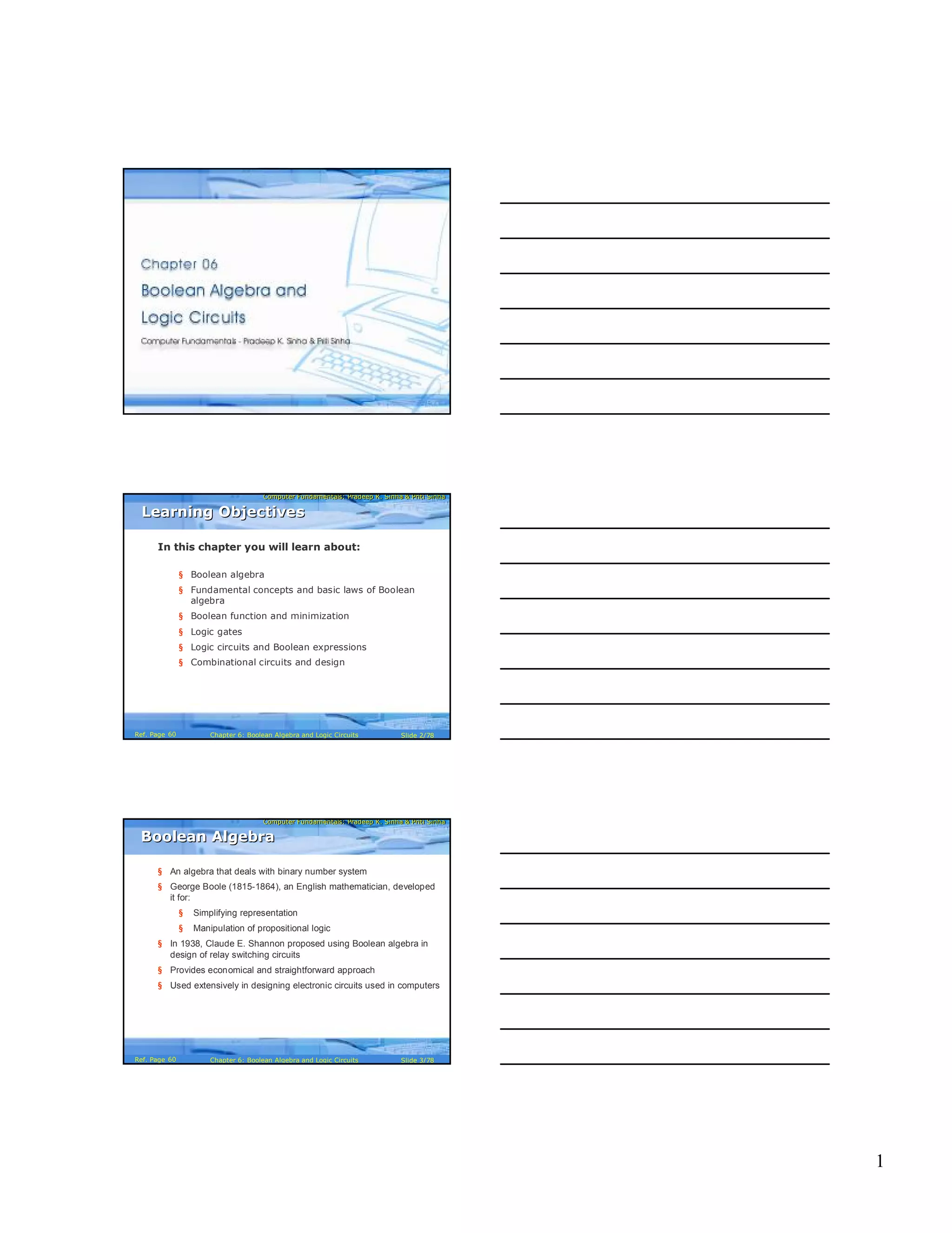
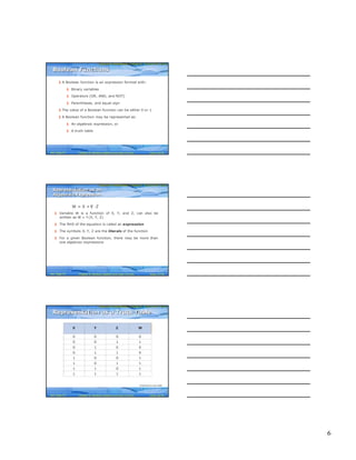
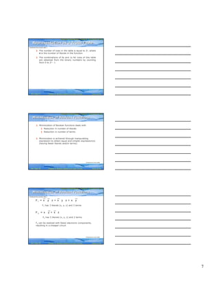
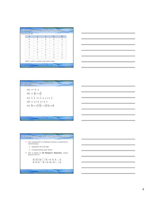
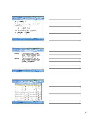
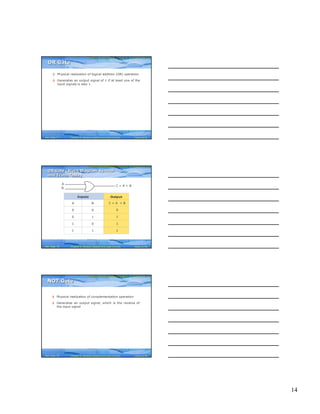
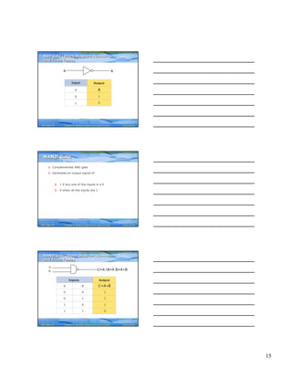
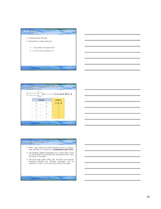
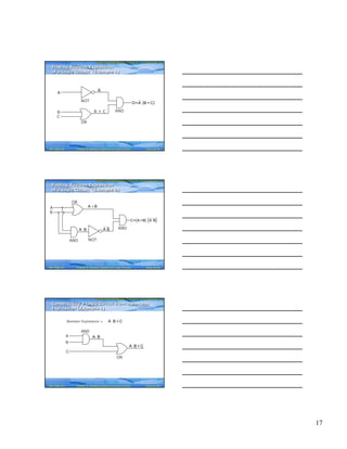
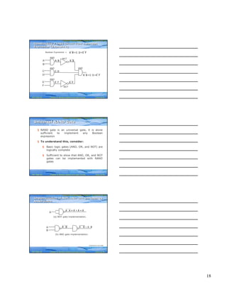
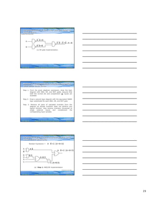
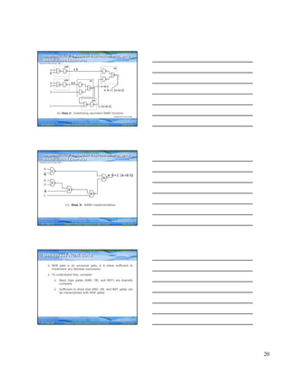
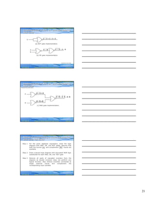
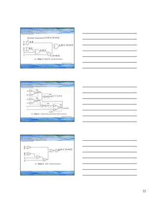
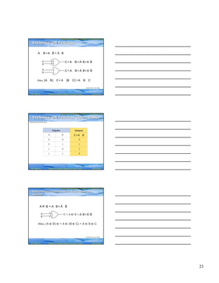
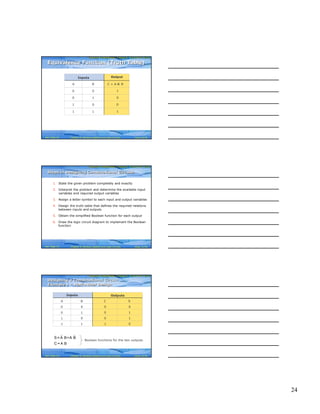
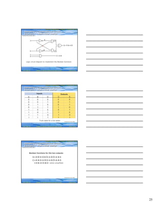
- The document discusses Boolean algebra and logic circuits. It covers Boolean algebra fundamentals such as binary operations, laws, theorems and their proofs.
- Boolean functions are represented using algebraic expressions or truth tables. Techniques to minimize Boolean functions by reducing literals and terms are explained.
- The basics of logic gates and how they are used to build combinational logic circuits are introduced.
Integral Calculus. - Differential Calculus - Integration as an Inverse Process of Differentiation - Methods of Integration - Integration using trigonometric identities - Integrals of Some Particular Functions - rational function - partial fraction - Integration by partial fractions - standard integrals - First and second fundamental theorem of integral calculus
This is a detailed review of ACM International Collegiate Programming Contest (ICPC) Northeastern European Regional Contest (NEERC) 2015 Problems. It includes a summary of problem and names of problem authors and detailed runs statistics for each problem. Video of the actual presentation that was recorded during NEERC is here https://www.youtube.com/watch?v=vn7v1MuWXdU (in Russian)
Note: there were only preliminary stats avaialble, because problems review was happening before before the closing ceremony. This published presentation has full stats.
I am Falid B. I am a Mathematical Statistics Assignment Help Expert at statisticshomeworkhelper.com. I hold a Master's in Statistics, from George Town, Malaysia.I have been helping students with their assignment for the past 6 years. I solve assignments related to Mathematical Statistics.
Visit statisticshomeworkhelper.com or email info@statisticshomeworkhelper.com.You can also call on +1 678 648 4277 for any assistance with Mathematical Statistics Assignment.
A discussion about the GCD of n numbers. Algorithms discussed with examples are Djikstra's Algo, Euclidean Algo, Binary GCD Algo, Lehmar's GCD Algo and Daykin's GCD Algo.
"Sparse Binary Zero-Sum Games". David Auger, Jialin Liu, Sylvie Ruette, David L. St-Pierre and Olivier Teytaud. The 6th Asian Conference on Machine Learning (ACML), 2014.
This is a detailed review of ACM International Collegiate Programming Contest (ICPC) Northeastern European Regional Contest (NEERC) 2016 Problems. It includes a summary of problem and names of problem authors and detailed runs statistics for each problem.
Problem statements are available here:
http://neerc.ifmo.ru/information/problems.pdf
The beginning of the following video has the actual review (in Russian): https://www.youtube.com/watch?v=fN25KkNYsjA
Euclid's Algorithm for Greatest Common Divisor - Time Complexity AnalysisAmrinder Arora
Euclid's algorithm for finding greatest common divisor is an elegant algorithm that can be written iteratively as well as recursively. The time complexity of this algorithm is O(log^2 n) where n is the larger of the two inputs.
I am Geoffrey J. I am a Signal Processing Assignment Expert at matlabassignmentexperts.com. I hold a Ph.D. in Matlab, Arizona State University. I have been helping students with their homework for the past 8 years. I solve assignments related to Signal Processing.
Visit matlabassignmentexperts.com or email info@matlabassignmentexperts.com. You can also call on +1 678 648 4277 for any assistance with Signal Processing Assignments.
I am Ben R. I am a Statistics Assignment Expert at statisticshomeworkhelper.com. I hold a Ph.D. in Statistics, from University of Denver, USA. I have been helping students with their homework for the past 5 years. I solve assignments related to Statistics.
Visit statisticshomeworkhelper.com or email info@statisticshomeworkhelper.com.
You can also call on +1 678 648 4277 for any assistance with Statistics Assignment.
I am Duncan V. I am a Digital Signal Processing Assignment Expert at matlabassignmentexperts.com. I hold a Ph.D. in Matlab, Ball State University, Indiana. I have been helping students with their homework for the past 8 years. I solve assignments related to Digital Signal Processing.
Visit matlabassignmentexperts.com or email info@matlabassignmentexperts.com.
You can also call on +1 678 648 4277 for any assistance with Digital Signal Processing Assignments.
A SURVEY ON ELLIPTIC CURVE DIGITAL SIGNATURE ALGORITHM AND ITS VARIANTScsandit
The Elliptic Curve Digital Signature Algorithm (ECDSA) is an elliptic curve variant of the
Digital Signature Algorithm (DSA). It gives cryptographically strong digital signatures making
use of Elliptic curve discrete logarithmic problem. It uses arithmetic with much smaller
numbers 160/256 bits instead of 1024/2048 bits in RSA and DSA and provides the same level of
security. The ECDSA was accepted in 1999 as an ANSI standard, and was accepted in 2000 as
IEEE and NIST standards. It was also accepted in 1998 as an ISO standard. Many cryptologist
have studied security aspects of ECDSA and proposed different variants. In this paper, we
discuss a detailed analysis of the original ECDSA and all its available variants in terms of the
security level and execution time of all the phases. To the best of our knowledge, this is a unique
attempt to juxtapose and compare the ECDSA with all of its variants.
Stratified Monte Carlo and bootstrapping for approximate Bayesian computationUmberto Picchini
Presented on 7 May 2020 at "One World Approximate Bayesian Computation (ABC) Seminar". A video is available at https://youtu.be/IOPnRfAJ_W8
Approximate Bayesian computation (ABC) is computationally intensive for complex model simulators. To exploit expensive simulations, data-resampling via bootstrapping was used with success in [1] to obtain many artificial datasets at little cost and construct a synthetic likelihood. When using the same approach within ABC to produce a pseudo-marginal ABC-MCMC algorithm, the posterior variance is inflated, thus producing biased posterior inference. Here we use stratified Monte Carlo to considerably reduce the bias induced by data resampling. We also show that it is possible to obtain reliable inference using a larger than usual ABC threshold, by employing stratified Monte Carlo. Finally, we show that with stratified sampling we obtain a less variable ABC likelihood. In our paper [2] we consider simulation studies for static (Gaussian, g-and-k distribution, Ising model) and dynamic models (Lotka-Volterra). For the Lotka-Volterra case study, we compare our results against a standard pseudo-Marginal ABC and find that our approach is four times more efficient and, given limited computational budget, it explores the posterior surface more thoroughly. A comparison against state-of-art sequential Monte Carlo ABC is also reported.
References
[1] R. G. Everitt (2017). Bootstrapped synthetic likelihood. arXiv:1711.05825.
[2] U. Picchini, R.G. Everitt (2019). Stratified sampling and resampling for approximateBayesian computation. arXiv:1905.07976
Unix and Shell Programming,
Q P Code: 60305.
Additional Mathematics I
Q P Code: 60306
Computer Organization and Architecture
Q P Code: 62303
Data Structures Using C
Q P Code: 60303
Discrete Mathematical Structures
Q P Code: 60304
Engineering Mathematics - III
Q P Code: 60301
Soft Skill Development
Q P Code: 60307
Gaps between the theory and practice of large-scale matrix-based network comp...David Gleich
I discuss some runtimes for the personalized PageRank vector and how it relates to open questions in how we should tackle these network based measures via matrix computations.
Fast relaxation methods for the matrix exponential David Gleich
The matrix exponential is a matrix computing primitive used in link prediction and community detection. We describe a fast method to compute it using relaxation on a large linear system of equations. This enables us to compute a column of the matrix exponential is sublinear time, or under a second on a standard desktop computer.
zkStudyClub - Improving performance of non-native arithmetic in SNARKs (Ivo K...Alex Pruden
In this zkStudyClub session, Ivo presents techniques for applying the log-derivative lookup tables in a circuit using LegoSNARK-style commitment. As an application, we show how this lookup table can be used to implement range checks, specifically applying it to the non-native arithmetic. Using these optimisations, we were able to reduce the proof time for BN254 pairing in Groth16 to approx 5s (MBP M1). The technique also works for PLONKish arithmetisation.
RankBrain is an algorithm to understand the structure of sentence written by users especially when there is use of conjunction, preposition, and articles in a query.
1. 1
Computer Fundamentals: Pradeep K. Sinha & Priti SinhaComputer Fundamentals: Pradeep K. Sinha & Priti Sinha
Slide 1/78Chapter 6: Boolean Algebra and Logic CircuitsRef. Page
Computer Fundamentals: Pradeep K. Sinha & Priti SinhaComputer Fundamentals: Pradeep K. Sinha & Priti Sinha
Slide 2/78Chapter 6: Boolean Algebra and Logic CircuitsRef. Page
In this chapter you will learn about:
§ Boolean algebra
§ Fundamental concepts and basic laws of Boolean
algebra
§ Boolean function and minimization
§ Logic gates
§ Logic circuits and Boolean expressions
§ Combinational circuits and design
Learning ObjectivesLearning Objectives
60
Computer Fundamentals: Pradeep K. Sinha & Priti SinhaComputer Fundamentals: Pradeep K. Sinha & Priti Sinha
Slide 3/78Chapter 6: Boolean Algebra and Logic CircuitsRef. Page
§ An algebra that deals with binary number system
§ George Boole (1815-1864), an English mathematician, developed
it for:
§ Simplifying representation
§ Manipulation of propositional logic
§ In 1938, Claude E. Shannon proposed using Boolean algebra in
design of relay switching circuits
§ Provides economical and straightforward approach
§ Used extensively in designing electronic circuits used in computers
Boolean AlgebraBoolean Algebra
60
2. 2
Computer Fundamentals: Pradeep K. Sinha & Priti SinhaComputer Fundamentals: Pradeep K. Sinha & Priti Sinha
Slide 4/78Chapter 6: Boolean Algebra and Logic CircuitsRef. Page
§ Use of Binary Digit
§ Boolean equations can have either of two possible
values, 0 and 1
§ Logical Addition
§ Symbol ‘+’, also known as ‘OR’ operator, used for
logical addition. Follows law of binary addition
§ Logical Multiplication
§ Symbol ‘.’, also known as ‘AND’ operator, used for
logical multiplication. Follows law of binary
multiplication
§ Complementation
§ Symbol ‘-’, also known as ‘NOT’ operator, used for
complementation. Follows law of binary compliment
Fundamental Concepts of Boolean AlgebraFundamental Concepts of Boolean Algebra
61
Computer Fundamentals: Pradeep K. Sinha & Priti SinhaComputer Fundamentals: Pradeep K. Sinha & Priti Sinha
Slide 5/78Chapter 6: Boolean Algebra and Logic CircuitsRef. Page
§ Each operator has a precedence level
§ Higher the operator’s precedence level, earlier it is evaluated
§ Expression is scanned from left to right
§ First, expressions enclosed within parentheses are evaluated
§ Then, all complement (NOT) operations are performed
§ Then, all ‘⋅’ (AND) operations are performed
§ Finally, all ‘+’ (OR) operations are performed
Operator PrecedenceOperator Precedence
(Continued on next slide)
62
Computer Fundamentals: Pradeep K. Sinha & Priti SinhaComputer Fundamentals: Pradeep K. Sinha & Priti Sinha
Slide 6/78Chapter 6: Boolean Algebra and Logic CircuitsRef. Page
X Y Z+ ⋅
1st
2nd
3rd
Operator PrecedenceOperator Precedence
(Continued from previous slide..)
62
3. 3
Computer Fundamentals: Pradeep K. Sinha & Priti SinhaComputer Fundamentals: Pradeep K. Sinha & Priti Sinha
Slide 7/78Chapter 6: Boolean Algebra and Logic CircuitsRef. Page
Postulate 1:
(a) A = 0, if and only if, A is not equal to 1
(b) A = 1, if and only if, A is not equal to 0
Postulate 2:
(a) x + 0 = x
(b) x ⋅ 1 = x
Postulate 3: Commutative Law
(a) x + y = y + x
(b) x ⋅ y = y ⋅ x
Postulates of Boolean AlgebraPostulates of Boolean Algebra
(Continued on next slide)
62
Computer Fundamentals: Pradeep K. Sinha & Priti SinhaComputer Fundamentals: Pradeep K. Sinha & Priti Sinha
Slide 8/78Chapter 6: Boolean Algebra and Logic CircuitsRef. Page
Postulate 4: Associative Law
(a) x + (y + z) = (x + y) + z
(b) x ⋅ (y ⋅ z) = (x ⋅ y) ⋅ z
Postulate 5: Distributive Law
(a) x ⋅ (y + z) = (x ⋅ y) + (x ⋅ z)
(b) x + (y ⋅ z) = (x + y) ⋅ (x + z)
Postulate 6:
(a) x + = 1
(b) x ⋅ = 0
x
x
Postulates of Boolean AlgebraPostulates of Boolean Algebra
(Continued from previous slide..)
62
Computer Fundamentals: Pradeep K. Sinha & Priti SinhaComputer Fundamentals: Pradeep K. Sinha & Priti Sinha
Slide 9/78Chapter 6: Boolean Algebra and Logic CircuitsRef. Page
0 + 0 = 01 + 0 = 0 + 1 = 11 + 1 = 1Row 1
1 ⋅ 1 = 10 ⋅ 1 = 1 ⋅ 0 = 00 ⋅ 0 = 0Row 2
Column 3Column 2Column 1
There is a precise duality between the operators . (AND) and +
(OR), and the digits 0 and 1.
For example, in the table below, the second row is obtained from
the first row and vice versa simply by interchanging ‘+’ with ‘.’
and ‘0’ with ‘1’
Therefore, if a particular theorem is proved, its dual theorem
automatically holds and need not be proved separately
The Principle of DualityThe Principle of Duality
63
4. 4
Computer Fundamentals: Pradeep K. Sinha & Priti SinhaComputer Fundamentals: Pradeep K. Sinha & Priti Sinha
Slide 10/78Chapter 6: Boolean Algebra and Logic CircuitsRef. Page
De Morgan’s
Law
= += ⋅6
x + ⋅ y = x + yx ⋅ + y = x ⋅ y5
Involution Law= x4
Absorption Lawx ⋅ x + y = xx + x ⋅ y = x3
x ⋅ 0 = 0x + 1 = 12
Idempotent Lawx ⋅ x = xx + x = x1
Name
(if any)
Dual Theorems/
Identities
Theorems/
Identities
Sr.
No.
x
x x
x y+ x y x y⋅ x y
Some Important Theorems of Boolean AlgebraSome Important Theorems of Boolean Algebra
63
Computer Fundamentals: Pradeep K. Sinha & Priti SinhaComputer Fundamentals: Pradeep K. Sinha & Priti Sinha
Slide 11/78Chapter 6: Boolean Algebra and Logic CircuitsRef. Page
The theorems of Boolean algebra may be proved by using
one of the following methods:
1. By using postulates to show that L.H.S. = R.H.S
2. By Perfect Induction or Exhaustive Enumeration method
where all possible combinations of variables involved in
L.H.S. and R.H.S. are checked to yield identical results
3. By the Principle of Duality where the dual of an already
proved theorem is derived from the proof of its
corresponding pair
Methods of Proving TheoremsMethods of Proving Theorems
63
Computer Fundamentals: Pradeep K. Sinha & Priti SinhaComputer Fundamentals: Pradeep K. Sinha & Priti Sinha
Slide 12/78Chapter 6: Boolean Algebra and Logic CircuitsRef. Page
Theorem:
x + x · y = x
Proof:
L.H.S.
= x + x ⋅ y
= x ⋅ 1 + x ⋅ y by postulate 2(b)
= x ⋅ (1 + y) by postulate 5(a)
= x ⋅ (y + 1) by postulate 3(a)
= x ⋅ 1 by theorem 2(a)
= x by postulate 2(b)
= R.H.S.
Proving a Theorem by Using Postulates
(Example)
Proving a Theorem by Using Postulates
(Example)
64
5. 5
Computer Fundamentals: Pradeep K. Sinha & Priti SinhaComputer Fundamentals: Pradeep K. Sinha & Priti Sinha
Slide 13/78Chapter 6: Boolean Algebra and Logic CircuitsRef. Page
Proving a Theorem by Perfect Induction
(Example)
Proving a Theorem by Perfect Induction
(Example)
Theorem:
x + x · y = x
=
x y x ⋅ y x + x ⋅ y
0 0 0 0
0 1 0 0
1 0 0 1
1 1 1 1
64
Computer Fundamentals: Pradeep K. Sinha & Priti SinhaComputer Fundamentals: Pradeep K. Sinha & Priti Sinha
Slide 14/78Chapter 6: Boolean Algebra and Logic CircuitsRef. Page
Theorem:
x + x = x
Proof:
L.H.S.
= x + x
= (x + x) ⋅ 1 by postulate 2(b)
= (x + x) ⋅ (x + ) by postulate 6(a)
= x + x ⋅ by postulate 5(b)
= x + 0 by postulate 6(b)
= x by postulate 2(a)
= R.H.S.
X
X
Proving a Theorem by the
Principle of Duality (Example)
Proving a Theorem by the
Principle of Duality (Example)
(Continued on next slide)
63
Computer Fundamentals: Pradeep K. Sinha & Priti SinhaComputer Fundamentals: Pradeep K. Sinha & Priti Sinha
Slide 15/78Chapter 6: Boolean Algebra and Logic CircuitsRef. Page
Dual Theorem:
x ⋅ x = x
Proof:
L.H.S.
= x ⋅ x
= x ⋅ x + 0 by postulate 2(a)
= x ⋅ x + x ⋅ by postulate 6(b)
= x ⋅ (x + ) by postulate 5(a)
= x ⋅ 1 by postulate 6(a)
= x by postulate 2(b)
= R.H.S.
X
X
Notice that each step of
the proof of the dual
theorem is derived from
the proof of its
corresponding pair in
the original theorem
Proving a Theorem by the
Principle of Duality (Example)
Proving a Theorem by the
Principle of Duality (Example)
(Continued from previous slide..)
63
6. 6
Computer Fundamentals: Pradeep K. Sinha & Priti SinhaComputer Fundamentals: Pradeep K. Sinha & Priti Sinha
Slide 16/78Chapter 6: Boolean Algebra and Logic CircuitsRef. Page
§ A Boolean function is an expression formed with:
§ Binary variables
§ Operators (OR, AND, and NOT)
§ Parentheses, and equal sign
§ The value of a Boolean function can be either 0 or 1
§ A Boolean function may be represented as:
§ An algebraic expression, or
§ A truth table
Boolean FunctionsBoolean Functions
67
Computer Fundamentals: Pradeep K. Sinha & Priti SinhaComputer Fundamentals: Pradeep K. Sinha & Priti Sinha
Slide 17/78Chapter 6: Boolean Algebra and Logic CircuitsRef. Page
§ Variable W is a function of X, Y, and Z, can also be
written as W = f (X, Y, Z)
§ The RHS of the equation is called an expression
§ The symbols X, Y, Z are the literals of the function
§ For a given Boolean function, there may be more than
one algebraic expressions
YW = X + ·Z
Representation as an
Algebraic Expression
Representation as an
Algebraic Expression
67
Computer Fundamentals: Pradeep K. Sinha & Priti SinhaComputer Fundamentals: Pradeep K. Sinha & Priti Sinha
Slide 18/78Chapter 6: Boolean Algebra and Logic CircuitsRef. Page
0 0 0 0
0 0 1 1
0 1 0 0
0 1 1 0
1 0 0 1
1 0 1 1
1 1 0 1
1 1 1 1
X Y Z W
Representation as a Truth TableRepresentation as a Truth Table
(Continued on next slide)
67
7. 7
Computer Fundamentals: Pradeep K. Sinha & Priti SinhaComputer Fundamentals: Pradeep K. Sinha & Priti Sinha
Slide 19/78Chapter 6: Boolean Algebra and Logic CircuitsRef. Page
§ The number of rows in the table is equal to 2n, where
n is the number of literals in the function
§ The combinations of 0s and 1s for rows of this table
are obtained from the binary numbers by counting
from 0 to 2n - 1
Representation as a Truth TableRepresentation as a Truth Table
(Continued from previous slide..)
67
Computer Fundamentals: Pradeep K. Sinha & Priti SinhaComputer Fundamentals: Pradeep K. Sinha & Priti Sinha
Slide 20/78Chapter 6: Boolean Algebra and Logic CircuitsRef. Page
§ Minimization of Boolean functions deals with
§ Reduction in number of literals
§ Reduction in number of terms
§ Minimization is achieved through manipulating
expression to obtain equal and simpler expression(s)
(having fewer literals and/or terms)
Minimization of Boolean FunctionsMinimization of Boolean Functions
(Continued on next slide)
68
Computer Fundamentals: Pradeep K. Sinha & Priti SinhaComputer Fundamentals: Pradeep K. Sinha & Priti Sinha
Slide 21/78Chapter 6: Boolean Algebra and Logic CircuitsRef. Page
1F = x y z + x y z + x y⋅ ⋅ ⋅ ⋅ ⋅
F1 has 3 literals (x, y, z) and 3 terms
2F = x y + x z⋅ ⋅
F2 has 3 literals (x, y, z) and 2 terms
F2 can be realized with fewer electronic components,
resulting in a cheaper circuit
Minimization of Boolean FunctionsMinimization of Boolean Functions
(Continued from previous slide..)
(Continued on next slide)
68
8. 8
Computer Fundamentals: Pradeep K. Sinha & Priti SinhaComputer Fundamentals: Pradeep K. Sinha & Priti Sinha
Slide 22/78Chapter 6: Boolean Algebra and Logic CircuitsRef. Page
0 0 0 0 0
0 0 1 1 1
0 1 0 0 0
0 1 1 1 1
1 0 0 1 1
1 0 1 1 1
1 1 0 0 0
1 1 1 0 0
Both F1 and F2 produce the same result
x y z F1 F2
Minimization of Boolean FunctionsMinimization of Boolean Functions
(Continued from previous slide..)
68
Computer Fundamentals: Pradeep K. Sinha & Priti SinhaComputer Fundamentals: Pradeep K. Sinha & Priti Sinha
Slide 23/78Chapter 6: Boolean Algebra and Logic CircuitsRef. Page
( )
( ) ( ) ( )
(a) x x y
(b) x x y
(c) x y z x y z x y
(d) x y x z y z
(e) x y x z y z
+ ⋅
⋅ +
⋅ ⋅ + ⋅ ⋅ + ⋅
⋅ + ⋅ + ⋅
+ ⋅ + ⋅ +
Try out some Boolean Function
Minimization
Try out some Boolean Function
Minimization
69
Computer Fundamentals: Pradeep K. Sinha & Priti SinhaComputer Fundamentals: Pradeep K. Sinha & Priti Sinha
Slide 24/78Chapter 6: Boolean Algebra and Logic CircuitsRef. Page
§ The complement of a Boolean function is obtained by
interchanging:
§ Operators OR and AND
§ Complementing each literal
§ This is based on De Morgan’s theorems, whose
general form is:
A +A +A +...+A =A A A ... A
A A A ... A = A +A +A +...+A
⋅ ⋅ ⋅ ⋅
⋅ ⋅ ⋅ ⋅
3 n 1 2 3 n
1 2 3 n 1 2 3 n
1 2
Complement of a Boolean FunctionComplement of a Boolean Function
70
9. 9
Computer Fundamentals: Pradeep K. Sinha & Priti SinhaComputer Fundamentals: Pradeep K. Sinha & Priti Sinha
Slide 25/78Chapter 6: Boolean Algebra and Logic CircuitsRef. Page
To obtain , we first interchange the OR and the AND
operators giving
Now we complement each literal giving
1F =x y z+x y z⋅ ⋅ ⋅ ⋅
1F
( ) ( )x+y+z x+y+z⋅
( ) ( )1F = x+ y+z x+y+ z⋅
Complementing a Boolean Function (Example)Complementing a Boolean Function (Example)
71
Computer Fundamentals: Pradeep K. Sinha & Priti SinhaComputer Fundamentals: Pradeep K. Sinha & Priti Sinha
Slide 26/78Chapter 6: Boolean Algebra and Logic CircuitsRef. Page
Minterms : n variables forming an AND term, with
each variable being primed or unprimed,
provide 2n possible combinations called
minterms or standard products
Maxterms : n variables forming an OR term, with
each variable being primed or unprimed,
provide 2n possible combinations called
maxterms or standard sums
Canonical Forms of Boolean FunctionsCanonical Forms of Boolean Functions
71
Computer Fundamentals: Pradeep K. Sinha & Priti SinhaComputer Fundamentals: Pradeep K. Sinha & Priti Sinha
Slide 27/78Chapter 6: Boolean Algebra and Logic CircuitsRef. Page
MaxtermsMintermsVariables
DesignationTermDesignationTermzyx
111
011
101
001
110
010
100
000
Note that each minterm is the complement of its corresponding maxterm and vice-versa
x y z
x y z
x y z
x y z
x y z
x y z
x y z
x y z
⋅ ⋅
⋅ ⋅
⋅ ⋅
⋅ ⋅
⋅ ⋅
⋅ ⋅
⋅ ⋅
⋅ ⋅
x y z
x y z
x y z
x y z
x y z
x y z
x y z
x y z
+ +
+ +
+ +
+ +
+ +
+ +
+ +
+ +
m
m
m
m
m
m
m
m
0
1
2
3
4
5
6
7
M
M
M
M
M
M
M
M
0
1
2
3
4
5
6
7
Minterms and Maxterms for three VariablesMinterms and Maxterms for three Variables
71
10. 10
Computer Fundamentals: Pradeep K. Sinha & Priti SinhaComputer Fundamentals: Pradeep K. Sinha & Priti Sinha
Slide 28/78Chapter 6: Boolean Algebra and Logic CircuitsRef. Page
A sum-of-products (SOP) expression is a product term
(minterm) or several product terms (minterms)
logically added (ORed) together. Examples are:
x
x+y z
x y+x y
⋅
⋅ ⋅
x+ y
x y+z
x y+x y z
⋅
⋅ ⋅ ⋅
Sum-of-Products (SOP) ExpressionSum-of-Products (SOP) Expression
72
Computer Fundamentals: Pradeep K. Sinha & Priti SinhaComputer Fundamentals: Pradeep K. Sinha & Priti Sinha
Slide 29/78Chapter 6: Boolean Algebra and Logic CircuitsRef. Page
1. Construct a truth table for the given Boolean
function
2. Form a minterm for each combination of the
variables, which produces a 1 in the function
3. The desired expression is the sum (OR) of all the
minterms obtained in Step 2
Steps to Express a Boolean Function
in its Sum-of-Products Form
Steps to Express a Boolean Function
in its Sum-of-Products Form
72
Computer Fundamentals: Pradeep K. Sinha & Priti SinhaComputer Fundamentals: Pradeep K. Sinha & Priti Sinha
Slide 30/78Chapter 6: Boolean Algebra and Logic CircuitsRef. Page
x y z F1
0 0 0 0
0 0 1 1
0 1 0 0
0 1 1 0
1 0 0 1
1 0 1 0
1 1 0 0
1 1 1 1
The following 3 combinations of the variables produce a 1:
001, 100, and 111
Expressing a Function in its
Sum-of-Products Form (Example)
Expressing a Function in its
Sum-of-Products Form (Example)
(Continued on next slide)
73
11. 11
Computer Fundamentals: Pradeep K. Sinha & Priti SinhaComputer Fundamentals: Pradeep K. Sinha & Priti Sinha
Slide 31/78Chapter 6: Boolean Algebra and Logic CircuitsRef. Page
§ Their corresponding minterms are:
x y z, x y z, and x y z⋅ ⋅ ⋅ ⋅ ⋅ ⋅
§ Taking the OR of these minterms, we get
1 1 4 7F =x y z+x y z+x y z=m +m m⋅ ⋅ ⋅ ⋅ ⋅ ⋅ +
( ) ( )⋅ ⋅ ∑1F x y z = 1,4,7
Expressing a Function in its
Sum-of-Products Form (Example)
Expressing a Function in its
Sum-of-Products Form (Example)
(Continued from previous slide..)
72
Computer Fundamentals: Pradeep K. Sinha & Priti SinhaComputer Fundamentals: Pradeep K. Sinha & Priti Sinha
Slide 32/78Chapter 6: Boolean Algebra and Logic CircuitsRef. Page
A product-of-sums (POS) expression is a sum term
(maxterm) or several sum terms (maxterms) logically
multiplied (ANDed) together. Examples are:
( )
x
x+y
x+y z⋅
( ) ( ) ( )
( ) ( )
( ) ( )
x+y x+y x+y
x + y x+ y+z
x+y x+y
⋅ ⋅
⋅
⋅
Product-of Sums (POS) ExpressionProduct-of Sums (POS) Expression
74
Computer Fundamentals: Pradeep K. Sinha & Priti SinhaComputer Fundamentals: Pradeep K. Sinha & Priti Sinha
Slide 33/78Chapter 6: Boolean Algebra and Logic CircuitsRef. Page
1. Construct a truth table for the given Boolean function
2. Form a maxterm for each combination of the variables,
which produces a 0 in the function
3. The desired expression is the product (AND) of all the
maxterms obtained in Step 2
Steps to Express a Boolean Function
in its Product-of-Sums Form
Steps to Express a Boolean Function
in its Product-of-Sums Form
74
12. 12
Computer Fundamentals: Pradeep K. Sinha & Priti SinhaComputer Fundamentals: Pradeep K. Sinha & Priti Sinha
Slide 34/78Chapter 6: Boolean Algebra and Logic CircuitsRef. Page
x y z F1
0 0 0 0
0 0 1 1
0 1 0 0
0 1 1 0
1 0 0 1
1 0 1 0
1 1 0 0
1 1 1 1
§ The following 5 combinations of variables produce a 0:
000, 010, 011, 101, and 110
Expressing a Function in its
Product-of-Sums Form
Expressing a Function in its
Product-of-Sums Form
(Continued on next slide)
73
Computer Fundamentals: Pradeep K. Sinha & Priti SinhaComputer Fundamentals: Pradeep K. Sinha & Priti Sinha
Slide 35/78Chapter 6: Boolean Algebra and Logic CircuitsRef. Page
§ Their corresponding maxterms are:
( ) ( ) ( )
( ) ( )
x+y+ z , x+y+ z , x+y+ z ,
x+y+ z and x+y+ z
§ Taking the AND of these maxterms, we get:
( ) ( ) ( ) ( )
( )
( ) ( )
⋅
⋅ ⋅ ⋅ ⋅
⋅ ⋅ ⋅1
0 2 3 5 6
1
=M M M M M
= Π 0,2,3,5,6
F = x+y+z x+y+z x+y+z x+y+z
x+y+z
F x,y,z
Expressing a Function in its
Product-of-Sums Form
Expressing a Function in its
Product-of-Sums Form
(Continued from previous slide..)
74
Computer Fundamentals: Pradeep K. Sinha & Priti SinhaComputer Fundamentals: Pradeep K. Sinha & Priti Sinha
Slide 36/78Chapter 6: Boolean Algebra and Logic CircuitsRef. Page
To convert from one canonical form to another,
interchange the symbol and list those numbers missing
from the original form.
Example:
( ) ( ) ( )
( ) ( ) ( )
F x,y,z = Π 0,2,4,5 = Σ 1,3,6,7
F x,y,z = Σ 1,4,7 = Σ 0,2,3,5,6
Conversion Between Canonical Forms (Sum-of-
Products and Product-of-Sums)
Conversion Between Canonical Forms (Sum-of-
Products and Product-of-Sums)
76
13. 13
Computer Fundamentals: Pradeep K. Sinha & Priti SinhaComputer Fundamentals: Pradeep K. Sinha & Priti Sinha
Slide 37/78Chapter 6: Boolean Algebra and Logic CircuitsRef. Page
§ Logic gates are electronic circuits that operate on
one or more input signals to produce standard output
signal
§ Are the building blocks of all the circuits in a
computer
§ Some of the most basic and useful logic gates are
AND, OR, NOT, NAND and NOR gates
Logic GatesLogic Gates
77
Computer Fundamentals: Pradeep K. Sinha & Priti SinhaComputer Fundamentals: Pradeep K. Sinha & Priti Sinha
Slide 38/78Chapter 6: Boolean Algebra and Logic CircuitsRef. Page
§ Physical realization of logical multiplication (AND)
operation
§ Generates an output signal of 1 only if all input
signals are also 1
AND GateAND Gate
77
Computer Fundamentals: Pradeep K. Sinha & Priti SinhaComputer Fundamentals: Pradeep K. Sinha & Priti Sinha
Slide 39/78Chapter 6: Boolean Algebra and Logic CircuitsRef. Page
A
B
C = A ⋅ B
Inputs Output
A B C = A ⋅ B
0 0 0
0 1 0
1 0 0
1 1 1
AND Gate (Block Diagram Symbol
and Truth Table)
AND Gate (Block Diagram Symbol
and Truth Table)
77
14. 14
Computer Fundamentals: Pradeep K. Sinha & Priti SinhaComputer Fundamentals: Pradeep K. Sinha & Priti Sinha
Slide 40/78Chapter 6: Boolean Algebra and Logic CircuitsRef. Page
§ Physical realization of logical addition (OR) operation
§ Generates an output signal of 1 if at least one of the
input signals is also 1
OR GateOR Gate
77
Computer Fundamentals: Pradeep K. Sinha & Priti SinhaComputer Fundamentals: Pradeep K. Sinha & Priti Sinha
Slide 41/78Chapter 6: Boolean Algebra and Logic CircuitsRef. Page
C = A + B
A
B
Inputs
A B
0 0
0 1
1 0
1 1
Output
C = A + B
0
1
1
1
OR Gate (Block Diagram Symbol
and Truth Table)
OR Gate (Block Diagram Symbol
and Truth Table)
78
Computer Fundamentals: Pradeep K. Sinha & Priti SinhaComputer Fundamentals: Pradeep K. Sinha & Priti Sinha
Slide 42/78Chapter 6: Boolean Algebra and Logic CircuitsRef. Page
§ Physical realization of complementation operation
§ Generates an output signal, which is the reverse of
the input signal
NOT GateNOT Gate
78
15. 15
Computer Fundamentals: Pradeep K. Sinha & Priti SinhaComputer Fundamentals: Pradeep K. Sinha & Priti Sinha
Slide 43/78Chapter 6: Boolean Algebra and Logic CircuitsRef. Page
Input Output
A
0 1
1 0
A A
A
NOT Gate (Block Diagram Symbol
and Truth Table)
NOT Gate (Block Diagram Symbol
and Truth Table)
79
Computer Fundamentals: Pradeep K. Sinha & Priti SinhaComputer Fundamentals: Pradeep K. Sinha & Priti Sinha
Slide 44/78Chapter 6: Boolean Algebra and Logic CircuitsRef. Page
§ Complemented AND gate
§ Generates an output signal of:
§ 1 if any one of the inputs is a 0
§ 0 when all the inputs are 1
NAND GateNAND Gate
79
Computer Fundamentals: Pradeep K. Sinha & Priti SinhaComputer Fundamentals: Pradeep K. Sinha & Priti Sinha
Slide 45/78Chapter 6: Boolean Algebra and Logic CircuitsRef. Page
Inputs
A B
0 0
0 1
1 0
1 1
Output
1
1
1
0
A
B C=A B=A B=A+B↑ ⋅
C =A+B
NAND Gate (Block Diagram Symbol
and Truth Table)
NAND Gate (Block Diagram Symbol
and Truth Table)
79
16. 16
Computer Fundamentals: Pradeep K. Sinha & Priti SinhaComputer Fundamentals: Pradeep K. Sinha & Priti Sinha
Slide 46/78Chapter 6: Boolean Algebra and Logic CircuitsRef. Page
§ Complemented OR gate
§ Generates an output signal of:
§ 1 only when all inputs are 0
§ 0 if any one of inputs is a 1
NOR GateNOR Gate
79
Computer Fundamentals: Pradeep K. Sinha & Priti SinhaComputer Fundamentals: Pradeep K. Sinha & Priti Sinha
Slide 47/78Chapter 6: Boolean Algebra and Logic CircuitsRef. Page
Inputs
A B
0 0
0 1
1 0
1 1
Output
1
0
0
0
A
B ↓ + ⋅C=A B=A B=A B
⋅C =A B
NOR Gate (Block Diagram Symbol
and Truth Table)
NOR Gate (Block Diagram Symbol
and Truth Table)
80
Computer Fundamentals: Pradeep K. Sinha & Priti SinhaComputer Fundamentals: Pradeep K. Sinha & Priti Sinha
Slide 48/78Chapter 6: Boolean Algebra and Logic CircuitsRef. Page
§ When logic gates are interconnected to form a gating /
logic network, it is known as a combinational logic circuit
§ The Boolean algebra expression for a given logic circuit
can be derived by systematically progressing from input
to output on the gates
§ The three logic gates (AND, OR, and NOT) are logically
complete because any Boolean expression can be
realized as a logic circuit using only these three gates
Logic CircuitsLogic Circuits
80
17. 17
Computer Fundamentals: Pradeep K. Sinha & Priti SinhaComputer Fundamentals: Pradeep K. Sinha & Priti Sinha
Slide 49/78Chapter 6: Boolean Algebra and Logic CircuitsRef. Page
B
C
A
A
NOT
OR
B + C
( )⋅D=A B + C
AND
Finding Boolean Expression
of a Logic Circuit (Example 1)
Finding Boolean Expression
of a Logic Circuit (Example 1)
80
Computer Fundamentals: Pradeep K. Sinha & Priti SinhaComputer Fundamentals: Pradeep K. Sinha & Priti Sinha
Slide 50/78Chapter 6: Boolean Algebra and Logic CircuitsRef. Page
A
B
NOT
OR
( ) ( )C= A+B A B⋅ ⋅
A B⋅
AND
A B+
A B⋅ AND
Finding Boolean Expression
of a Logic Circuit (Example 2)
Finding Boolean Expression
of a Logic Circuit (Example 2)
81
Computer Fundamentals: Pradeep K. Sinha & Priti SinhaComputer Fundamentals: Pradeep K. Sinha & Priti Sinha
Slide 51/78Chapter 6: Boolean Algebra and Logic CircuitsRef. Page
OR
A B⋅
AND
A B + C⋅
A
B
C
Boolean Expression = A B + C⋅
Constructing a Logic Circuit from a Boolean
Expression (Example 1)
Constructing a Logic Circuit from a Boolean
Expression (Example 1)
83
18. 18
Computer Fundamentals: Pradeep K. Sinha & Priti SinhaComputer Fundamentals: Pradeep K. Sinha & Priti Sinha
Slide 52/78Chapter 6: Boolean Algebra and Logic CircuitsRef. Page
A B⋅
AND
A
B
Boolean Expression = A B+ C D+E F⋅ ⋅ ⋅
C D⋅
AND
C
D
E F⋅
AND
E
F
A B + C D +E F⋅ ⋅ ⋅
AND
A B⋅
NOT
E F⋅
NOT
Constructing a Logic Circuit from a Boolean
Expression (Example 2)
Constructing a Logic Circuit from a Boolean
Expression (Example 2)
83
Computer Fundamentals: Pradeep K. Sinha & Priti SinhaComputer Fundamentals: Pradeep K. Sinha & Priti Sinha
Slide 53/78Chapter 6: Boolean Algebra and Logic CircuitsRef. Page
§ NAND gate is an universal gate, it is alone
sufficient to implement any Boolean
expression
§ To understand this, consider:
§ Basic logic gates (AND, OR, and NOT) are
logically complete
§ Sufficient to show that AND, OR, and NOT
gates can be implemented with NAND
gates
Universal NAND GateUniversal NAND Gate
84
Computer Fundamentals: Pradeep K. Sinha & Priti SinhaComputer Fundamentals: Pradeep K. Sinha & Priti Sinha
Slide 54/78Chapter 6: Boolean Algebra and Logic CircuitsRef. Page
(a) NOT gate implementation.
A
A A = A + A = A⋅
(b) AND gate implementation.
A A B A B⋅ = ⋅A B⋅
B
Implementation of NOT, AND and OR Gates by
NAND Gates
Implementation of NOT, AND and OR Gates by
NAND Gates
(Continued on next slide)
85
19. 19
Computer Fundamentals: Pradeep K. Sinha & Priti SinhaComputer Fundamentals: Pradeep K. Sinha & Priti Sinha
Slide 55/78Chapter 6: Boolean Algebra and Logic CircuitsRef. Page
⋅ = = +A B A +B A B
A
B
A A = A⋅
B B =B⋅
(c) OR gate implementation.
Implementation of NOT, AND and OR Gates by
NAND Gates
Implementation of NOT, AND and OR Gates by
NAND Gates
(Continued from previous slide..)
85
Computer Fundamentals: Pradeep K. Sinha & Priti SinhaComputer Fundamentals: Pradeep K. Sinha & Priti Sinha
Slide 56/78Chapter 6: Boolean Algebra and Logic CircuitsRef. Page
Step 1: From the given algebraic expression, draw the logic
diagram with AND, OR, and NOT gates. Assume that
both the normal (A) and complement ( ) inputs are
available
Step 2: Draw a second logic diagram with the equivalent NAND
logic substituted for each AND, OR, and NOT gate
Step 3: Remove all pairs of cascaded inverters from the
diagram as double inversion does not perform any
logical function. Also remove inverters connected to
single external inputs and complement the
corresponding input variable
A
Method of Implementing a Boolean Expression
with Only NAND Gates
Method of Implementing a Boolean Expression
with Only NAND Gates
85
Computer Fundamentals: Pradeep K. Sinha & Priti SinhaComputer Fundamentals: Pradeep K. Sinha & Priti Sinha
Slide 57/78Chapter 6: Boolean Algebra and Logic CircuitsRef. Page
Boolean Expression =
(a) Step 1: AND/OR implementation
A
B
D
C
A
A B⋅
B
A +B D⋅
B D⋅
( )C A+B D⋅ ⋅
( )⋅ ⋅ ⋅A B + C A +B D
Implementing a Boolean Expression with Only
NAND Gates (Example)
Implementing a Boolean Expression with Only
NAND Gates (Example)
(Continued on next slide)
87
20. 20
Computer Fundamentals: Pradeep K. Sinha & Priti SinhaComputer Fundamentals: Pradeep K. Sinha & Priti Sinha
Slide 58/78Chapter 6: Boolean Algebra and Logic CircuitsRef. Page
(b) Step 2: Substituting equivalent NAND functions
AND
OR
OR
5
3
4
A
AND
B
D
2
AND
A
C
1
B
A B⋅
( )A B +C A+B D⋅ ⋅ ⋅
A+B D⋅
( )C A+B D⋅ ⋅
B D⋅
Implementing a Boolean Expression with Only
NAND Gates (Example)
Implementing a Boolean Expression with Only
NAND Gates (Example)
(Continued from previous slide..)
(Continued on next slide)
87
Computer Fundamentals: Pradeep K. Sinha & Priti SinhaComputer Fundamentals: Pradeep K. Sinha & Priti Sinha
Slide 59/78Chapter 6: Boolean Algebra and Logic CircuitsRef. Page
A
B
D
C
B
(c) Step 3: NAND implementation.
( )⋅ ⋅ ⋅A B+C A+B D
A
1
2
3
4
5
Implementing a Boolean Expression with Only
NAND Gates (Example)
Implementing a Boolean Expression with Only
NAND Gates (Example)
(Continued from previous slide..)
87
Computer Fundamentals: Pradeep K. Sinha & Priti SinhaComputer Fundamentals: Pradeep K. Sinha & Priti Sinha
Slide 60/78Chapter 6: Boolean Algebra and Logic CircuitsRef. Page
§ NOR gate is an universal gate, it is alone sufficient to
implement any Boolean expression
§ To understand this, consider:
§ Basic logic gates (AND, OR, and NOT) are logically
complete
§ Sufficient to show that AND, OR, and NOT gates can
be implemented with NOR gates
Universal NOR GateUniversal NOR Gate
89
21. 21
Computer Fundamentals: Pradeep K. Sinha & Priti SinhaComputer Fundamentals: Pradeep K. Sinha & Priti Sinha
Slide 61/78Chapter 6: Boolean Algebra and Logic CircuitsRef. Page
(a) NOT gate implementation.
A A A = A A = A+ ⋅
(b) OR gate implementation.
A A B A B+ = +A B+
B
Implementation of NOT, OR and AND Gates by
NOR Gates
Implementation of NOT, OR and AND Gates by
NOR Gates
(Continued on next slide)
89
Computer Fundamentals: Pradeep K. Sinha & Priti SinhaComputer Fundamentals: Pradeep K. Sinha & Priti Sinha
Slide 62/78Chapter 6: Boolean Algebra and Logic CircuitsRef. Page
= ⋅ = ⋅A +B A B A B
A
B
A A = A+
B B =B+
(c) AND gate implementation.
Implementation of NOT, OR and AND Gates by
NOR Gates
Implementation of NOT, OR and AND Gates by
NOR Gates
(Continued from previous slide..)
89
Computer Fundamentals: Pradeep K. Sinha & Priti SinhaComputer Fundamentals: Pradeep K. Sinha & Priti Sinha
Slide 63/78Chapter 6: Boolean Algebra and Logic CircuitsRef. Page
Step 1: For the given algebraic expression, draw the logic
diagram with AND, OR, and NOT gates. Assume that
both the normal and complement inputs are
available
Step 2: Draw a second logic diagram with equivalent NOR logic
substituted for each AND, OR, and NOT gate
Step 3: Remove all parts of cascaded inverters from the
diagram as double inversion does not perform any
logical function. Also remove inverters connected to
single external inputs and complement the
corresponding input variable
( )A( )A
Method of Implementing a Boolean Expression
with Only NOR Gates
Method of Implementing a Boolean Expression
with Only NOR Gates
89
22. 22
Computer Fundamentals: Pradeep K. Sinha & Priti SinhaComputer Fundamentals: Pradeep K. Sinha & Priti Sinha
Slide 64/78Chapter 6: Boolean Algebra and Logic CircuitsRef. Page
A
B
D
C
A
A B⋅
B
(a) Step 1: AND/OR implementation.
A +B D⋅
B D⋅
( )C A+B D⋅ ⋅
( )⋅ ⋅ ⋅A B+C A+B D
Boolean Expression
=
( )⋅ ⋅ ⋅A B+C A+B D
Implementing a Boolean Expression with Only
NOR Gates (Examples)
Implementing a Boolean Expression with Only
NOR Gates (Examples)
(Continued from previous slide..)
(Continued on next slide)
90
Computer Fundamentals: Pradeep K. Sinha & Priti SinhaComputer Fundamentals: Pradeep K. Sinha & Priti Sinha
Slide 65/78Chapter 6: Boolean Algebra and Logic CircuitsRef. Page
(b) Step 2: Substituting equivalent NOR functions.
2
1
AN
DA
B
D
B
AN
D
OR
5 6
4
AN
D
OR
3
A
C
A B⋅
B D⋅
( )C A+B D⋅ ⋅
( )⋅ ⋅ ⋅BA + C A+B D
A+B D⋅
Implementing a Boolean Expression with Only
NOR Gates (Examples)
Implementing a Boolean Expression with Only
NOR Gates (Examples)
(Continued from previous slide..)
(Continued on next slide)
90
Computer Fundamentals: Pradeep K. Sinha & Priti SinhaComputer Fundamentals: Pradeep K. Sinha & Priti Sinha
Slide 66/78Chapter 6: Boolean Algebra and Logic CircuitsRef. Page
A
B
D
B
(c) Step 3: NOR implementation.
( )⋅ ⋅ ⋅A B+C A+B D
A
3
4
5
1
2
6
C
Implementing a Boolean Expression with Only
NOR Gates (Examples)
Implementing a Boolean Expression with Only
NOR Gates (Examples)
(Continued from previous slide..)
91
23. 23
Computer Fundamentals: Pradeep K. Sinha & Priti SinhaComputer Fundamentals: Pradeep K. Sinha & Priti Sinha
Slide 67/78Chapter 6: Boolean Algebra and Logic CircuitsRef. Page
⊕ ⋅ ⋅A B =A B + A B
C = A B = A B+A B⊕ ⋅ ⋅
C = A B = A B+A B⊕ ⋅ ⋅⊕
A
B
A
B
( ) ( )Also, ⊕ ⊕ ⊕ ⊕ ⊕ ⊕A B C = A B C = A B C
Exclusive-OR FunctionExclusive-OR Function
(Continued on next slide)
91
Computer Fundamentals: Pradeep K. Sinha & Priti SinhaComputer Fundamentals: Pradeep K. Sinha & Priti Sinha
Slide 68/78Chapter 6: Boolean Algebra and Logic CircuitsRef. Page
Inputs
A B
0 0
0 1
1 0
1 1
Output
0
1
1
0
C =A B⊕
Exclusive-OR Function (Truth Table)Exclusive-OR Function (Truth Table)
(Continued from previous slide..)
92
Computer Fundamentals: Pradeep K. Sinha & Priti SinhaComputer Fundamentals: Pradeep K. Sinha & Priti Sinha
Slide 69/78Chapter 6: Boolean Algebra and Logic CircuitsRef. Page
A
B
C = A € B = A B+A B⋅ ⋅
Also, (A € B) € = A € (B € C) = A € B € C
Equivalence Function with Block Diagram
Symbol
Equivalence Function with Block Diagram
Symbol
(Continued on next slide)
⋅ ⋅A B = A B+ A B€
91
24. 24
Computer Fundamentals: Pradeep K. Sinha & Priti SinhaComputer Fundamentals: Pradeep K. Sinha & Priti Sinha
Slide 70/78Chapter 6: Boolean Algebra and Logic CircuitsRef. Page
Inputs
A B
0 0
0 1
1 0
1 1
Output
1
0
0
1
C = A € B
Equivalence Function (Truth Table)Equivalence Function (Truth Table)
92
Computer Fundamentals: Pradeep K. Sinha & Priti SinhaComputer Fundamentals: Pradeep K. Sinha & Priti Sinha
Slide 71/78Chapter 6: Boolean Algebra and Logic CircuitsRef. Page
1. State the given problem completely and exactly
2. Interpret the problem and determine the available input
variables and required output variables
3. Assign a letter symbol to each input and output variables
4. Design the truth table that defines the required relations
between inputs and outputs
5. Obtain the simplified Boolean function for each output
6. Draw the logic circuit diagram to implement the Boolean
function
Steps in Designing Combinational CircuitsSteps in Designing Combinational Circuits
93
Computer Fundamentals: Pradeep K. Sinha & Priti SinhaComputer Fundamentals: Pradeep K. Sinha & Priti Sinha
Slide 72/78Chapter 6: Boolean Algebra and Logic CircuitsRef. Page
S = A B+A B⋅ ⋅
C = A B⋅
Boolean functions for the two outputs.
Inputs
A B
0 0
0 1
1 0
1 1
Outputs
0
0
0
1
C
0
1
1
0
S
Designing a Combinational Circuit
Example 1 – Half-Adder Design
Designing a Combinational Circuit
Example 1 – Half-Adder Design
93
25. 25
Computer Fundamentals: Pradeep K. Sinha & Priti SinhaComputer Fundamentals: Pradeep K. Sinha & Priti Sinha
Slide 73/78Chapter 6: Boolean Algebra and Logic CircuitsRef. Page
Logic circuit diagram to implement the Boolean functions
A
B
A
B
⋅ ⋅S = A B+A B
C = A B⋅
A
B
A B⋅
A B⋅
Designing a Combinational Circuit
Example 1 – Half-Adder Design
Designing a Combinational Circuit
Example 1 – Half-Adder Design
(Continued from previous slide..)
94
Computer Fundamentals: Pradeep K. Sinha & Priti SinhaComputer Fundamentals: Pradeep K. Sinha & Priti Sinha
Slide 74/78Chapter 6: Boolean Algebra and Logic CircuitsRef. Page
Truth table for a full adder
Designing a Combinational Circuit
Example 2 – Full-Adder Design
Designing a Combinational Circuit
Example 2 – Full-Adder Design
Inputs
A B
0 0
0 0
0 1
0 1
Outputs
0
0
0
1
C
0
1
1
0
SD
0
1
0
1
1 0
1 0
0
1
1
0
0
1
1 1
1 1
1
1
0
1
0
1
(Continued on next slide)
94
Computer Fundamentals: Pradeep K. Sinha & Priti SinhaComputer Fundamentals: Pradeep K. Sinha & Priti Sinha
Slide 75/78Chapter 6: Boolean Algebra and Logic CircuitsRef. Page
S = A B D+A B D+ A B D+A B D⋅ ⋅ ⋅ ⋅ ⋅ ⋅ ⋅ ⋅
C = A B D+A B D+ A B D+A B D⋅ ⋅ ⋅ ⋅ ⋅ ⋅ ⋅ ⋅
= A B+A D+B D⋅ ⋅ ⋅ (when simplified)
Boolean functions for the two outputs:
Designing a Combinational Circuit
Example 2 – Full-Adder Design
Designing a Combinational Circuit
Example 2 – Full-Adder Design
(Continued from previous slide..)
(Continued on next slide)
95
26. 26
Computer Fundamentals: Pradeep K. Sinha & Priti SinhaComputer Fundamentals: Pradeep K. Sinha & Priti Sinha
Slide 76/78Chapter 6: Boolean Algebra and Logic CircuitsRef. Page
(a) Logic circuit diagram for sums
A
B
D
A
B
A
B
A
B
D
D
D
S
A B D⋅ ⋅
A B D⋅ ⋅
A B D⋅ ⋅
A B D⋅ ⋅
Designing a Combinational Circuit
Example 2 – Full-Adder Design
Designing a Combinational Circuit
Example 2 – Full-Adder Design
(Continued from previous slide..)
(Continued on next slide)
95
Computer Fundamentals: Pradeep K. Sinha & Priti SinhaComputer Fundamentals: Pradeep K. Sinha & Priti Sinha
Slide 77/78Chapter 6: Boolean Algebra and Logic CircuitsRef. Page
C
A B⋅
A D⋅
B D⋅
A
B
A
D
B
D
(b) Logic circuit diagram for carry
Designing a Combinational Circuit
Example 2 – Full-Adder Design
Designing a Combinational Circuit
Example 2 – Full-Adder Design
(Continued from previous slide..)
95
Computer Fundamentals: Pradeep K. Sinha & Priti SinhaComputer Fundamentals: Pradeep K. Sinha & Priti Sinha
Slide 78/78Chapter 6: Boolean Algebra and Logic CircuitsRef. Page
Key Words/PhrasesKey Words/Phrases
§ Absorption law
§ AND gate
§ Associative law
§ Boolean algebra
§ Boolean expression
§ Boolean functions
§ Boolean identities
§ Canonical forms for
Boolean functions
§ Combination logic
circuits
§ Cumulative law
§ Complement of a
function
§ Complementation
§ De Morgan’s law
§ Distributive law
§ Dual identities
§ Equivalence function
§ Exclusive-OR function
§ Exhaustive enumeration
method
§ Half-adder
§ Idempotent law
§ Involution law
§ Literal
§ Logic circuits
§ Logic gates
§ Logical addition
§ Logical multiplication
§ Maxterms
§ Minimization of Boolean
functions
§ Minterms
§ NAND gate
§ NOT gate
§ Operator precedence
§ OR gate
§ Parallel Binary Adder
§ Perfect induction
method
§ Postulates of Boolean
algebra
§ Principle of duality
§ Product-of-Sums
expression
§ Standard forms
§ Sum-of Products
expression
§ Truth table
§ Universal NAND gate
§ Universal NOR gate
97