SlideShare a Scribd company logo
1 of 2
Use Case Diagrams
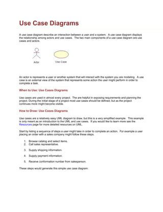
A use case diagram describe an interaction between a user and a system. A use case diagram displays
the relationship among actors and use cases. The two main components of a use case diagram are use
cases and actors.


An actor is represents a user or another system that will interact with the system you are modeling. A use
case is an external view of the system that represents some action the user might perform in order to
complete a task.

When to Use: Use Cases Diagrams

Use cases are used in almost every project. The are helpful in exposing requirements and planning the
project. During the initial stage of a project most use cases should be defined, but as the project
continues more might become visible.

How to Draw: Use Cases Diagrams

Use cases are a relatively easy UML diagram to draw, but this is a very simplified example. This example
is only meant as an introduction to the UML and use cases. If you would like to learn more see the
Resources page for more detailed resources on UML.

Start by listing a sequence of steps a user might take in order to complete an action. For example a user
placing an order with a sales company might follow these steps.

    1. Browse catalog and select items.
    2. Call sales representative.

    3. Supply shipping information.

    4. Supply payment information.

    5. Receive conformation number from salesperson.

These steps would generate this simple use case diagram:
This example shows the customer as a actor because the customer is using the ordering system. The
diagram takes the simple steps listed above and shows them as actions the customer might perform. The
salesperson could also be included in this use case diagram because the salesperson is also interacting
with the ordering system.

From this simple diagram the requirements of the ordering system can easily be derived. The system will
need to be able to perform actions for all of the use cases listed. As the project progresses other use
cases might appear. The customer might have a need to add an item to an order that has already been
placed. This diagram can easily be expanded until a complete description of the ordering system is
derived capturing all of the requirements that the system will need to perform.

More Related Content

What's hot (20)

DFD for E-Commerce Website
DFD for E-Commerce WebsiteDFD for E-Commerce Website
DFD for E-Commerce Website
 
Student database management system PROJECT
Student database management system PROJECTStudent database management system PROJECT
Student database management system PROJECT
 
Client Server Architecture
Client Server ArchitectureClient Server Architecture
Client Server Architecture
 
Diagrams
DiagramsDiagrams
Diagrams
 
Use case diagrams
Use case diagramsUse case diagrams
Use case diagrams
 
Use case-diagrams
Use case-diagramsUse case-diagrams
Use case-diagrams
 
Erd practice exercises
Erd practice exercisesErd practice exercises
Erd practice exercises
 
[[Srs]] online shopping website for TYBSC IT
[[Srs]] online shopping website for TYBSC IT[[Srs]] online shopping website for TYBSC IT
[[Srs]] online shopping website for TYBSC IT
 
Overview of UML Diagrams
Overview of UML DiagramsOverview of UML Diagrams
Overview of UML Diagrams
 
Introduction to UML
Introduction to UMLIntroduction to UML
Introduction to UML
 
Srs
SrsSrs
Srs
 
Schema
SchemaSchema
Schema
 
UML and Software Modeling Tools.pptx
UML and Software Modeling Tools.pptxUML and Software Modeling Tools.pptx
UML and Software Modeling Tools.pptx
 
Uml class-diagram
Uml class-diagramUml class-diagram
Uml class-diagram
 
Types of UML diagrams
Types of UML diagramsTypes of UML diagrams
Types of UML diagrams
 
Entity relationship diagram (erd)
Entity relationship diagram (erd)Entity relationship diagram (erd)
Entity relationship diagram (erd)
 
Data Flow Diagram
Data Flow DiagramData Flow Diagram
Data Flow Diagram
 
Furniture shop management system project report
Furniture shop management system project reportFurniture shop management system project report
Furniture shop management system project report
 
Dbms Notes Lecture 9 : Specialization, Generalization and Aggregation
Dbms Notes Lecture 9 : Specialization, Generalization and AggregationDbms Notes Lecture 9 : Specialization, Generalization and Aggregation
Dbms Notes Lecture 9 : Specialization, Generalization and Aggregation
 
Social & professional issues in IT
Social & professional issues in ITSocial & professional issues in IT
Social & professional issues in IT
 

Viewers also liked

Viewers also liked (14)

Ch5b
Ch5bCh5b
Ch5b
 
Lecture 06 syntax analysis 3
Lecture 06 syntax analysis 3Lecture 06 syntax analysis 3
Lecture 06 syntax analysis 3
 
Syntax
SyntaxSyntax
Syntax
 
Lexical Analysis
Lexical AnalysisLexical Analysis
Lexical Analysis
 
Syntax directed-translation
Syntax directed-translationSyntax directed-translation
Syntax directed-translation
 
Syntax directed translation
Syntax directed translationSyntax directed translation
Syntax directed translation
 
Compiler Design
Compiler DesignCompiler Design
Compiler Design
 
Syntax (Part 1)
Syntax (Part 1)Syntax (Part 1)
Syntax (Part 1)
 
Syntax
SyntaxSyntax
Syntax
 
Lexical analysis-using-lex
Lexical analysis-using-lexLexical analysis-using-lex
Lexical analysis-using-lex
 
Role-of-lexical-analysis
Role-of-lexical-analysisRole-of-lexical-analysis
Role-of-lexical-analysis
 
System Programming Overview
System Programming OverviewSystem Programming Overview
System Programming Overview
 
Recognition-of-tokens
Recognition-of-tokensRecognition-of-tokens
Recognition-of-tokens
 
Finite automata-for-lexical-analysis
Finite automata-for-lexical-analysisFinite automata-for-lexical-analysis
Finite automata-for-lexical-analysis
 

Similar to Use Case Diagrams Explained

Use Case Analysis and Diagramming
 Use Case Analysis and Diagramming Use Case Analysis and Diagramming
Use Case Analysis and DiagrammingOrnella Dunn
 
Lab 3 Introduction to the UML - how to create a use case diagram
Lab 3 Introduction to the UML - how to create a use case diagramLab 3 Introduction to the UML - how to create a use case diagram
Lab 3 Introduction to the UML - how to create a use case diagramFarah Ahmed
 
SELECT21.pptx
SELECT21.pptxSELECT21.pptx
SELECT21.pptxdevnasra1
 
Lesson02_Use Case Diagrams
Lesson02_Use Case DiagramsLesson02_Use Case Diagrams
Lesson02_Use Case DiagramsMarwa Ali Eissa
 
[RPL2] Pertemuan 3 - UML dan USECASE VIEW
[RPL2] Pertemuan 3 - UML dan USECASE VIEW[RPL2] Pertemuan 3 - UML dan USECASE VIEW
[RPL2] Pertemuan 3 - UML dan USECASE VIEWrizki adam kurniawan
 
Software Engineering Tools and Practices.pdf
Software Engineering Tools and Practices.pdfSoftware Engineering Tools and Practices.pdf
Software Engineering Tools and Practices.pdfMeagGhn
 
Onlineshopping 121105040955-phpapp02
Onlineshopping 121105040955-phpapp02Onlineshopping 121105040955-phpapp02
Onlineshopping 121105040955-phpapp02Shuchi Singla
 
Onlineshoppingonline shopping
Onlineshoppingonline shoppingOnlineshoppingonline shopping
Onlineshoppingonline shoppingHardik Padhy
 
Quality Assurance. Quality Assurance Approach. White Box
Quality Assurance. Quality Assurance Approach. White BoxQuality Assurance. Quality Assurance Approach. White Box
Quality Assurance. Quality Assurance Approach. White BoxKimberly Jones
 
Use Case Diagram.pptx
Use Case Diagram.pptxUse Case Diagram.pptx
Use Case Diagram.pptxGenta Sahuri
 
OOAD U1.pptx
OOAD U1.pptxOOAD U1.pptx
OOAD U1.pptxanguraju1
 
Use Case Modeling In UML
Use Case Modeling In UMLUse Case Modeling In UML
Use Case Modeling In UMLSyed Hassan Ali
 

Similar to Use Case Diagrams Explained (20)

Use Case UML Diagram
Use Case UML DiagramUse Case UML Diagram
Use Case UML Diagram
 
Design UML diagrams
Design UML diagramsDesign UML diagrams
Design UML diagrams
 
Design UML diagrams
Design UML diagramsDesign UML diagrams
Design UML diagrams
 
Use Case Analysis and Diagramming
 Use Case Analysis and Diagramming Use Case Analysis and Diagramming
Use Case Analysis and Diagramming
 
Lab 3 Introduction to the UML - how to create a use case diagram
Lab 3 Introduction to the UML - how to create a use case diagramLab 3 Introduction to the UML - how to create a use case diagram
Lab 3 Introduction to the UML - how to create a use case diagram
 
SELECT21.pptx
SELECT21.pptxSELECT21.pptx
SELECT21.pptx
 
Lesson02_Use Case Diagrams
Lesson02_Use Case DiagramsLesson02_Use Case Diagrams
Lesson02_Use Case Diagrams
 
[RPL2] Pertemuan 3 - UML dan USECASE VIEW
[RPL2] Pertemuan 3 - UML dan USECASE VIEW[RPL2] Pertemuan 3 - UML dan USECASE VIEW
[RPL2] Pertemuan 3 - UML dan USECASE VIEW
 
Use case modeling
Use case modelingUse case modeling
Use case modeling
 
Software Engineering Tools and Practices.pdf
Software Engineering Tools and Practices.pdfSoftware Engineering Tools and Practices.pdf
Software Engineering Tools and Practices.pdf
 
UML Diagrams
UML DiagramsUML Diagrams
UML Diagrams
 
Onlineshopping 121105040955-phpapp02
Onlineshopping 121105040955-phpapp02Onlineshopping 121105040955-phpapp02
Onlineshopping 121105040955-phpapp02
 
Onlineshoppingonline shopping
Onlineshoppingonline shoppingOnlineshoppingonline shopping
Onlineshoppingonline shopping
 
Quality Assurance. Quality Assurance Approach. White Box
Quality Assurance. Quality Assurance Approach. White BoxQuality Assurance. Quality Assurance Approach. White Box
Quality Assurance. Quality Assurance Approach. White Box
 
Use Case Diagram.pptx
Use Case Diagram.pptxUse Case Diagram.pptx
Use Case Diagram.pptx
 
OOAD U1.pptx
OOAD U1.pptxOOAD U1.pptx
OOAD U1.pptx
 
Use Case Modeling In UML
Use Case Modeling In UMLUse Case Modeling In UML
Use Case Modeling In UML
 
Introduction to UML
Introduction to UMLIntroduction to UML
Introduction to UML
 
UML Design
UML DesignUML Design
UML Design
 
Use Cases
Use CasesUse Cases
Use Cases
 

More from Mir Majid

Dfd and flowchart
Dfd and flowchartDfd and flowchart
Dfd and flowchartMir Majid
 
.Net framework interview questions
.Net framework interview questions.Net framework interview questions
.Net framework interview questionsMir Majid
 
My sql technical reference manual
My sql technical reference manualMy sql technical reference manual
My sql technical reference manualMir Majid
 
Holographic memory
Holographic memoryHolographic memory
Holographic memoryMir Majid
 
Simulation programs
Simulation programsSimulation programs
Simulation programsMir Majid
 
8086 assembly language
8086 assembly language8086 assembly language
8086 assembly languageMir Majid
 
Lessons from life_2
Lessons from life_2Lessons from life_2
Lessons from life_2Mir Majid
 
Time management
Time managementTime management
Time managementMir Majid
 
Lest weforget
Lest weforget Lest weforget
Lest weforget Mir Majid
 
E hospital manager
E hospital managerE hospital manager
E hospital managerMir Majid
 

More from Mir Majid (19)

Dfd and flowchart
Dfd and flowchartDfd and flowchart
Dfd and flowchart
 
.Net framework interview questions
.Net framework interview questions.Net framework interview questions
.Net framework interview questions
 
My sql technical reference manual
My sql technical reference manualMy sql technical reference manual
My sql technical reference manual
 
Dotnet basics
Dotnet basicsDotnet basics
Dotnet basics
 
Holographic memory
Holographic memoryHolographic memory
Holographic memory
 
Data recovery
Data recoveryData recovery
Data recovery
 
Simulation programs
Simulation programsSimulation programs
Simulation programs
 
8086 assembly language
8086 assembly language8086 assembly language
8086 assembly language
 
Router bridge
Router bridgeRouter bridge
Router bridge
 
Assembler
AssemblerAssembler
Assembler
 
Lessons from life_2
Lessons from life_2Lessons from life_2
Lessons from life_2
 
Child faces 2
Child faces 2Child faces 2
Child faces 2
 
Time management
Time managementTime management
Time management
 
Lest weforget
Lest weforget Lest weforget
Lest weforget
 
E hospital manager
E hospital managerE hospital manager
E hospital manager
 
Crypt
CryptCrypt
Crypt
 
Smart cards
Smart cardsSmart cards
Smart cards
 
Rfid
RfidRfid
Rfid
 
Rfid seminar
Rfid seminarRfid seminar
Rfid seminar
 

Use Case Diagrams Explained

  • 1. Use Case Diagrams A use case diagram describe an interaction between a user and a system. A use case diagram displays the relationship among actors and use cases. The two main components of a use case diagram are use cases and actors. An actor is represents a user or another system that will interact with the system you are modeling. A use case is an external view of the system that represents some action the user might perform in order to complete a task. When to Use: Use Cases Diagrams Use cases are used in almost every project. The are helpful in exposing requirements and planning the project. During the initial stage of a project most use cases should be defined, but as the project continues more might become visible. How to Draw: Use Cases Diagrams Use cases are a relatively easy UML diagram to draw, but this is a very simplified example. This example is only meant as an introduction to the UML and use cases. If you would like to learn more see the Resources page for more detailed resources on UML. Start by listing a sequence of steps a user might take in order to complete an action. For example a user placing an order with a sales company might follow these steps. 1. Browse catalog and select items. 2. Call sales representative. 3. Supply shipping information. 4. Supply payment information. 5. Receive conformation number from salesperson. These steps would generate this simple use case diagram:
  • 2. This example shows the customer as a actor because the customer is using the ordering system. The diagram takes the simple steps listed above and shows them as actions the customer might perform. The salesperson could also be included in this use case diagram because the salesperson is also interacting with the ordering system. From this simple diagram the requirements of the ordering system can easily be derived. The system will need to be able to perform actions for all of the use cases listed. As the project progresses other use cases might appear. The customer might have a need to add an item to an order that has already been placed. This diagram can easily be expanded until a complete description of the ordering system is derived capturing all of the requirements that the system will need to perform.