Radiation can be ionizing or non-ionizing depending on its energy level. The three main mechanisms of heat transfer are conduction, convection, and radiation. Radiation is the transfer of heat via electromagnetic waves and does not require a medium. All objects emit radiation depending on their temperature according to the Stefan-Boltzman law. View factors describe the fraction of radiation emitted by one surface that is received by another based on their relative orientations. Conservation rules ensure view factors properly account for all radiation within an enclosure.


![φ
R·sin θ
Δφ
R
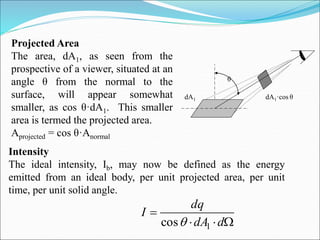
θ
dA1
dA2
Spherical Geometry
Since any surface will emit radiation outward
in all directions above the surface, the
spherical coordinate system provides a
convenient tool for analysis. The three basic
coordinates shown are R, φ, and θ,
representing the radial, azimuthal and zenith
directions.
In general dA1 will correspond to the emitting
surface or the source. The surface dA2 will
correspond to the receiving surface or the
target. Note that the area proscribed on the
hemisphere, dA2, may be written as: ][])sin[(2 dRdRdA
]sin2
2 ddRdA
Recalling the definition of the solid angle, = R2·dΩ
we find that: dΩ = sin θ·dθ·dφ
2dA](https://image.slidesharecdn.com/pptradiation-191114152340/85/Ppt-radiation-23-320.jpg)