This document provides instructions for operating an automated punch press system. It includes details about system parameters like accumulated count, panel width and length, hole diameter and spacing. It describes the control panel functions such as axis positioning, speed settings and debugging tools. The operation method section outlines the steps for setting processing points, parameters and running the system in manual and automatic modes. Mold replacement procedures are also summarized.
Modern precision manufacturing demands extreme dimensional accuracy and surface finish.Such performance is very difficult to achieve manually, if not impossible, even with expert operators. In cases where it is possible, it takes much higher time due to the need for frequent dimensional measurement to prevent overcutting. It is thus obvious that automated motion control would replace manual “handwheel” control in modern manufacturing. Development of computer numerically controlled (CNC) machines has also made possible the automation of the machining processes with flexibility to handle production of small to medium batch of parts. In the 1940s when the U.S. Air Force perceived the need to manufacture complex parts for highspeed aircraft. This led to the development of computer-based automatic machine tool controls also known as the Numerical Control (NC) systems. Commercial production of NC machine tools started around the fifties and sixties around the world. Note that at this time the microprocessor has not yet been invented. Initially, the CNC technology was applied on lathes, milling machines, etc. which could perform a single type of metal cutting operation. Later, attempt was made to handle a variety of workpieces that may require several different types machining operations and to finish them in a single set-up. Thus CNC machining Centres capable of performing multiple operations were developed. To start with, CNC machining centres were developed for machining prismatic components combining operations like milling, drilling, boring and tapping. Gradually machines for manufacturing cylindrical components, called turning centers were developed.
Automatically controlling a machine tool based on a set of pre-programmed machining and movement instructions is known as numerical control, or NC.In a typical NC system the motion and machining instructions and the related numerical data, together called a part program, used to be written on a punched tape. The part program is arranged in the form of blocks of information, each related to a particular operation in a sequence
of operations needed for producing a mechanical component. The punched tape used to be read one block at a time. Each block contained, in a particular syntax, information needed for processing a particular machining instruction such as, the segment length, its cutting speed, feed, etc. These pieces of information were related to the final dimensions of the workpiece (length, width, and radii of circles) and the contour forms (linear, circular, or other) as per the drawing. Based on these dimensions, motion commands were given separately for each axis of motion. Other instructions and related machining parameters, such as cutting speed, feed rate, as well as auxiliary functions related to coolant flow, spindle speed, part clamping, are also provided in part programs depending on manufacturing specifications such as tolerance and surface finish. Punched tapes are mostly obsolete.
Contents:
1. History
2. Introduction to CNC Milling
3. Elements of CNC Machine
4. How CNC Works
5. CNC Programming
6. Advantages and Disadvantages of CNC
7. Applications of CNC
This is the ppt of CNC turning with Fanuc system.It helps you to encourage your CNC programming skills,also in this ppt some theory of CNC turning are available which helps you to do the programming in the proper way.Here some points are given below to do the programming in the fanuc control CNC.
1 . How to make the turning job?
2. How to make the programming of fillet and chamfer in the different ways.
3. How to use the TNRC codes G41 and G42.
4. How to use the different tools in the different-different operations.
The all above points are very important and these points are available in this ppt.
RTK has universal CNC milling machine for manufacturing process. We have CNC machining centers with proven mechanical stability and high production efficiency.
This presentation is prepared as per syllabus of "COMMUNICATION ANALYSIS AND SKILL DEVELOPMENT PROGRAM (CASP)" prescribed by BOARD OF TECHNICAL EDUCATION, KARNATAKA for 5th sem diploma all branches.
This pptx is prepared by lots of information in websites,Textbooks(Author B
A Srinivas and M R Manjunath),And guidance of our lecturers Srinath V- B.E,FIE & M D Dayanand- B.E . SET Polytechnic, Melukote
CNC Programming for Begainer.
1.Easy Mehtod.
2.Complete Theoritical Knowledge.
3.Motion and coordinate system for NC machine.
4.Axes convention of VMC & HMC.
5.How to make Part Programming.
6.Coordinates System.
7.Programming Format.
8.List of G Codes And M Codes.
9.How to Use of Above Codes In Programme.
10.Reference Point and Return of Machine.
Saudi Arabia stands as a titan in the global energy landscape, renowned for its abundant oil and gas resources. It's the largest exporter of petroleum and holds some of the world's most significant reserves. Let's delve into the top 10 oil and gas projects shaping Saudi Arabia's energy future in 2024.
Water scarcity is the lack of fresh water resources to meet the standard water demand. There are two type of water scarcity. One is physical. The other is economic water scarcity.
Explore the innovative world of trenchless pipe repair with our comprehensive guide, "The Benefits and Techniques of Trenchless Pipe Repair." This document delves into the modern methods of repairing underground pipes without the need for extensive excavation, highlighting the numerous advantages and the latest techniques used in the industry.
Learn about the cost savings, reduced environmental impact, and minimal disruption associated with trenchless technology. Discover detailed explanations of popular techniques such as pipe bursting, cured-in-place pipe (CIPP) lining, and directional drilling. Understand how these methods can be applied to various types of infrastructure, from residential plumbing to large-scale municipal systems.
Ideal for homeowners, contractors, engineers, and anyone interested in modern plumbing solutions, this guide provides valuable insights into why trenchless pipe repair is becoming the preferred choice for pipe rehabilitation. Stay informed about the latest advancements and best practices in the field.
Final project report on grocery store management system..pdfKamal Acharya
In today’s fast-changing business environment, it’s extremely important to be able to respond to client needs in the most effective and timely manner. If your customers wish to see your business online and have instant access to your products or services.
Online Grocery Store is an e-commerce website, which retails various grocery products. This project allows viewing various products available enables registered users to purchase desired products instantly using Paytm, UPI payment processor (Instant Pay) and also can place order by using Cash on Delivery (Pay Later) option. This project provides an easy access to Administrators and Managers to view orders placed using Pay Later and Instant Pay options.
In order to develop an e-commerce website, a number of Technologies must be studied and understood. These include multi-tiered architecture, server and client-side scripting techniques, implementation technologies, programming language (such as PHP, HTML, CSS, JavaScript) and MySQL relational databases. This is a project with the objective to develop a basic website where a consumer is provided with a shopping cart website and also to know about the technologies used to develop such a website.
This document will discuss each of the underlying technologies to create and implement an e- commerce website.
Hybrid optimization of pumped hydro system and solar- Engr. Abdul-Azeez.pdffxintegritypublishin
Advancements in technology unveil a myriad of electrical and electronic breakthroughs geared towards efficiently harnessing limited resources to meet human energy demands. The optimization of hybrid solar PV panels and pumped hydro energy supply systems plays a pivotal role in utilizing natural resources effectively. This initiative not only benefits humanity but also fosters environmental sustainability. The study investigated the design optimization of these hybrid systems, focusing on understanding solar radiation patterns, identifying geographical influences on solar radiation, formulating a mathematical model for system optimization, and determining the optimal configuration of PV panels and pumped hydro storage. Through a comparative analysis approach and eight weeks of data collection, the study addressed key research questions related to solar radiation patterns and optimal system design. The findings highlighted regions with heightened solar radiation levels, showcasing substantial potential for power generation and emphasizing the system's efficiency. Optimizing system design significantly boosted power generation, promoted renewable energy utilization, and enhanced energy storage capacity. The study underscored the benefits of optimizing hybrid solar PV panels and pumped hydro energy supply systems for sustainable energy usage. Optimizing the design of solar PV panels and pumped hydro energy supply systems as examined across diverse climatic conditions in a developing country, not only enhances power generation but also improves the integration of renewable energy sources and boosts energy storage capacities, particularly beneficial for less economically prosperous regions. Additionally, the study provides valuable insights for advancing energy research in economically viable areas. Recommendations included conducting site-specific assessments, utilizing advanced modeling tools, implementing regular maintenance protocols, and enhancing communication among system components.
Automobile Management System Project Report.pdfKamal Acharya
The proposed project is developed to manage the automobile in the automobile dealer company. The main module in this project is login, automobile management, customer management, sales, complaints and reports. The first module is the login. The automobile showroom owner should login to the project for usage. The username and password are verified and if it is correct, next form opens. If the username and password are not correct, it shows the error message.
When a customer search for a automobile, if the automobile is available, they will be taken to a page that shows the details of the automobile including automobile name, automobile ID, quantity, price etc. “Automobile Management System” is useful for maintaining automobiles, customers effectively and hence helps for establishing good relation between customer and automobile organization. It contains various customized modules for effectively maintaining automobiles and stock information accurately and safely.
When the automobile is sold to the customer, stock will be reduced automatically. When a new purchase is made, stock will be increased automatically. While selecting automobiles for sale, the proposed software will automatically check for total number of available stock of that particular item, if the total stock of that particular item is less than 5, software will notify the user to purchase the particular item.
Also when the user tries to sale items which are not in stock, the system will prompt the user that the stock is not enough. Customers of this system can search for a automobile; can purchase a automobile easily by selecting fast. On the other hand the stock of automobiles can be maintained perfectly by the automobile shop manager overcoming the drawbacks of existing system.
Forklift Classes Overview by Intella PartsIntella Parts
Discover the different forklift classes and their specific applications. Learn how to choose the right forklift for your needs to ensure safety, efficiency, and compliance in your operations.
For more technical information, visit our website https://intellaparts.com
Cosmetic shop management system project report.pdfKamal Acharya
Buying new cosmetic products is difficult. It can even be scary for those who have sensitive skin and are prone to skin trouble. The information needed to alleviate this problem is on the back of each product, but it's thought to interpret those ingredient lists unless you have a background in chemistry.
Instead of buying and hoping for the best, we can use data science to help us predict which products may be good fits for us. It includes various function programs to do the above mentioned tasks.
Data file handling has been effectively used in the program.
The automated cosmetic shop management system should deal with the automation of general workflow and administration process of the shop. The main processes of the system focus on customer's request where the system is able to search the most appropriate products and deliver it to the customers. It should help the employees to quickly identify the list of cosmetic product that have reached the minimum quantity and also keep a track of expired date for each cosmetic product. It should help the employees to find the rack number in which the product is placed.It is also Faster and more efficient way.
Vaccine management system project report documentation..pdfKamal Acharya
The Division of Vaccine and Immunization is facing increasing difficulty monitoring vaccines and other commodities distribution once they have been distributed from the national stores. With the introduction of new vaccines, more challenges have been anticipated with this additions posing serious threat to the already over strained vaccine supply chain system in Kenya.
Courier management system project report.pdfKamal Acharya
It is now-a-days very important for the people to send or receive articles like imported furniture, electronic items, gifts, business goods and the like. People depend vastly on different transport systems which mostly use the manual way of receiving and delivering the articles. There is no way to track the articles till they are received and there is no way to let the customer know what happened in transit, once he booked some articles. In such a situation, we need a system which completely computerizes the cargo activities including time to time tracking of the articles sent. This need is fulfilled by Courier Management System software which is online software for the cargo management people that enables them to receive the goods from a source and send them to a required destination and track their status from time to time.
COLLEGE BUS MANAGEMENT SYSTEM PROJECT REPORT.pdfKamal Acharya
The College Bus Management system is completely developed by Visual Basic .NET Version. The application is connect with most secured database language MS SQL Server. The application is develop by using best combination of front-end and back-end languages. The application is totally design like flat user interface. This flat user interface is more attractive user interface in 2017. The application is gives more important to the system functionality. The application is to manage the student’s details, driver’s details, bus details, bus route details, bus fees details and more. The application has only one unit for admin. The admin can manage the entire application. The admin can login into the application by using username and password of the admin. The application is develop for big and small colleges. It is more user friendly for non-computer person. Even they can easily learn how to manage the application within hours. The application is more secure by the admin. The system will give an effective output for the VB.Net and SQL Server given as input to the system. The compiled java program given as input to the system, after scanning the program will generate different reports. The application generates the report for users. The admin can view and download the report of the data. The application deliver the excel format reports. Because, excel formatted reports is very easy to understand the income and expense of the college bus. This application is mainly develop for windows operating system users. In 2017, 73% of people enterprises are using windows operating system. So the application will easily install for all the windows operating system users. The application-developed size is very low. The application consumes very low space in disk. Therefore, the user can allocate very minimum local disk space for this application.
Overview of the fundamental roles in Hydropower generation and the components involved in wider Electrical Engineering.
This paper presents the design and construction of hydroelectric dams from the hydrologist’s survey of the valley before construction, all aspects and involved disciplines, fluid dynamics, structural engineering, generation and mains frequency regulation to the very transmission of power through the network in the United Kingdom.
Author: Robbie Edward Sayers
Collaborators and co editors: Charlie Sims and Connor Healey.
(C) 2024 Robbie E. Sayers
About
Indigenized remote control interface card suitable for MAFI system CCR equipment. Compatible for IDM8000 CCR. Backplane mounted serial and TCP/Ethernet communication module for CCR remote access. IDM 8000 CCR remote control on serial and TCP protocol.
• Remote control: Parallel or serial interface.
• Compatible with MAFI CCR system.
• Compatible with IDM8000 CCR.
• Compatible with Backplane mount serial communication.
• Compatible with commercial and Defence aviation CCR system.
• Remote control system for accessing CCR and allied system over serial or TCP.
• Indigenized local Support/presence in India.
• Easy in configuration using DIP switches.
Technical Specifications
Indigenized remote control interface card suitable for MAFI system CCR equipment. Compatible for IDM8000 CCR. Backplane mounted serial and TCP/Ethernet communication module for CCR remote access. IDM 8000 CCR remote control on serial and TCP protocol.
Key Features
Indigenized remote control interface card suitable for MAFI system CCR equipment. Compatible for IDM8000 CCR. Backplane mounted serial and TCP/Ethernet communication module for CCR remote access. IDM 8000 CCR remote control on serial and TCP protocol.
• Remote control: Parallel or serial interface
• Compatible with MAFI CCR system
• Copatiable with IDM8000 CCR
• Compatible with Backplane mount serial communication.
• Compatible with commercial and Defence aviation CCR system.
• Remote control system for accessing CCR and allied system over serial or TCP.
• Indigenized local Support/presence in India.
Application
• Remote control: Parallel or serial interface.
• Compatible with MAFI CCR system.
• Compatible with IDM8000 CCR.
• Compatible with Backplane mount serial communication.
• Compatible with commercial and Defence aviation CCR system.
• Remote control system for accessing CCR and allied system over serial or TCP.
• Indigenized local Support/presence in India.
• Easy in configuration using DIP switches.
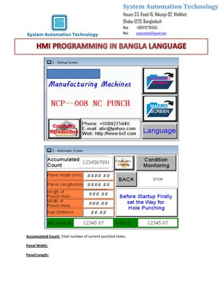
1. System Automation Technology
House-23, Road-15, Nikunjo-02, Khilkhet,
Dhaka-1229, Bangladesh
Mob: +8801737784651
Mail: sysautotech@gmail.com
Accumulated Count: Total number of current punched holes.
Panel Width:
Panel Length:
2. System Automation Technology
House-23, Road-15, Nikunjo-02, Khilkhet,
Dhaka-1229, Bangladesh
Mob: +8801737784651
Mail: sysautotech@gmail.com
Length of Punched Hole (Diameter): set the length of length/ round stamping in mm
Width of Punched Hole: Set the width of the circular stamping. Stamping without setting unit mm
Gap distance: Gap distance between punched work pieces
X & Y-axis: Display the current coordinates of X & Y axis
Number of Punched Holes: Displays the current number of punched holes on a panel
Number of current Rows: Displays the current number of punched rows
Number of current Row Holes: Displays the punched holes of each rows
Horizontal Punched holes: Display the punched holes of each rows
Vertical Punched holes: Display the punched holes of each panel/Coolum
Speed of punch: set the speed (Hz) of punch press display value (for VFD) max 50hz
Operating Instruction:
Auxilary Setting:
Clutch Inching: Inching of Pneumatic clutch
Oil Inching: Manual control of lubrication pump
Return to Base Point: Return Horizontal & vertical axes to the base points
3. System Automation Technology
House-23, Road-15, Nikunjo-02, Khilkhet,
Dhaka-1229, Bangladesh
Mob: +8801737784651
Mail: sysautotech@gmail.com
Axle Zero Cleaning: Press this key to conduct zero cleaning for current coordinates
Processing Points: (x,y) axis run to the starting points
Horizontal Moving speed: SET the speed of X-axis servo, for equipment debugging, don’t change after
debugging
Vertical Moving speed: SET the speed of Y-axis servo, for equipment debugging, don’t change after
debugging
Manual Moving speed: set the manual speed
Moving Time-delay: set the interval time for servo motor during debugging, it’s not required to be
change
Speed Inc/Dec time: For equipment debugging
Auto Return to Zero speed: Set the speed of servo motor returning into the base points under the
automatic operation mode
Unloading Distance: set the distance of X-axis from the processing point to the unloading point
System Debugging:
4. System Automation Technology
House-23, Road-15, Nikunjo-02, Khilkhet,
Dhaka-1229, Bangladesh
Mob: +8801737784651
Mail: sysautotech@gmail.com
Horizontal Axis Working Point:
Set the position from the base point to the first hole of x-axis
Vertical Axis Working Point:
Set the position from the base point to the first hole of y-axis
Horizontal Length (mm):
Set the operating Distance of X-axis Servo motor (mm)
Vertical Length (mm):
Set the operating Distance of Y-axis Servo motor (mm)
Gripping time Delay: Set the gripping Time delay
Time for Lubricating Operation:
Set the Oil pump RUN time (Sec) under automatic operation
5. System Automation Technology
House-23, Road-15, Nikunjo-02, Khilkhet,
Dhaka-1229, Bangladesh
Mob: +8801737784651
Mail: sysautotech@gmail.com
Time for Lubricating Suspension:
Set the suspension time of lub pump (sec) under automatic operation
Close –to-the-switch-reaction Time: for equipment debugging
Punching Completion time Delay:
Suspension time between punching completion to return to base point under automatic
operation
Close-to-the-switch fine time: for equipment debugging
Blowing Time Delay:
Working hour of blowing under automatic operation
MASTER PANEL
1.Power supply Indicator
2.Electromagnet
Switching off of pneumatic clutch, pneumatic clutch is controlled by PLC when it is
turned off, the pneumatic clutch is turned on when it is turned on. It is used for mold
adjustment
3.Debugging
After setting system parameters, select automatic operation mode, Press this key. The
servo runs according to the designed program, the punch press doesn’t work.
6. System Automation Technology
House-23, Road-15, Nikunjo-02, Khilkhet,
Dhaka-1229, Bangladesh
Mob: +8801737784651
Mail: sysautotech@gmail.com
4.Emergency Stop
OPERATION METHOD
1.Return to Base point
Set the desktop to manual operation mode, manually move X & Y axis to slide to the
middle position, Press “ ” then X & Y axis return to the base point.
2.Set Processing point
Place the punched materials on to the slide & Clamp them, manually move X & Y axis to
move the punched materials to the mold punching position & cover the mold trim line,
record the coordinates of X & Y axis. Record the position distance divided by 2 into
“ ”as processing points of X & y axis.
3.Parameter setting
Record the length & width of punched materials, sizes & distance of punched holes into
corresponding parameter forms, then the system will automatically calculate.
Notes: The Power Supply should be turned off & returned on after parameter change,
thus to facilitates the system update.
4.Operation
(1) After parameter setting put the operation mode selector switch to manual,
move X & Y axis to middle position of the slide, Press “ ”
then X & Y axis return to the base point.
(2) Press “Processing points” X & Y axis move automatically from base point to
processing point.
(3) Press “ ” (Axis/ coordinate zero cleaning) Coordinate position
will automatically change into zero.
(4) Press “Punch Press Startup” to run punch press motor.
7. System Automation Technology
House-23, Road-15, Nikunjo-02, Khilkhet,
Dhaka-1229, Bangladesh
Mob: +8801737784651
Mail: sysautotech@gmail.com
(5) Press “Single Punching” the clutch of punch press pulls in, the puncher moves
downward, one punching is stopped, the slide & puncher operate synchronously
& move by one working position. When the manual operation is conducted to
the last row, pls inspect the position of clamps in the punch press mold, it should
not enter the mold.
(6) After manual operation has no problem, put the operation mode selector switch
to automatic, press “Continuous Punching “to automatically operate to one
piece of punched materials has been fully punched according to the parameters
set by the operator & Automatically collect the scarp.
MOLD REPLACEMENT & OPERATION
1. Press “STOP”
2.
3.