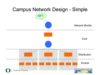
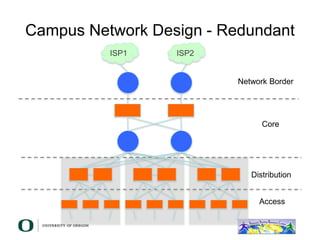
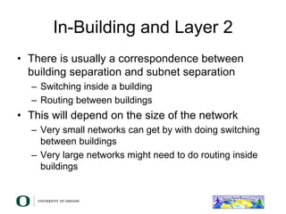
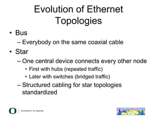
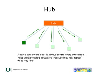
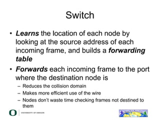
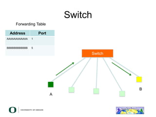
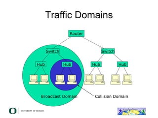
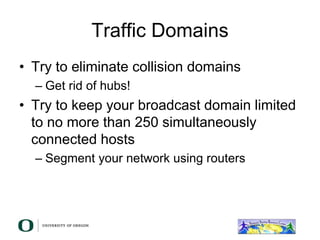
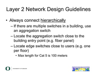
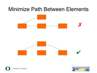
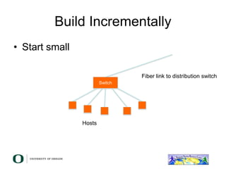
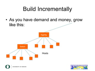
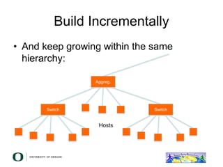
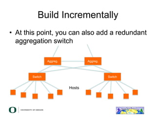
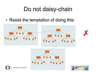
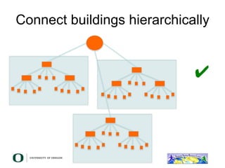
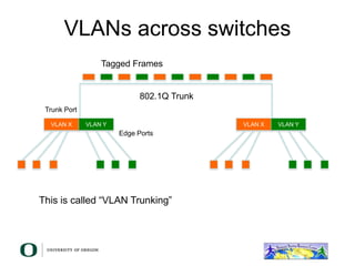
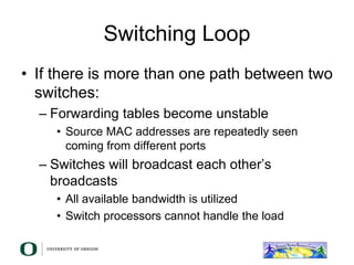
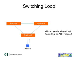
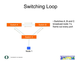
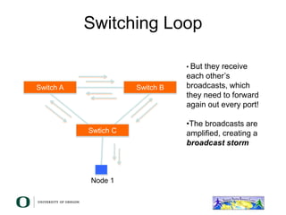
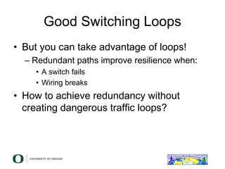
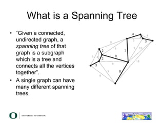
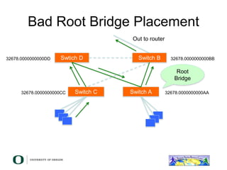
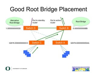
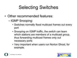
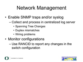
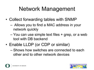
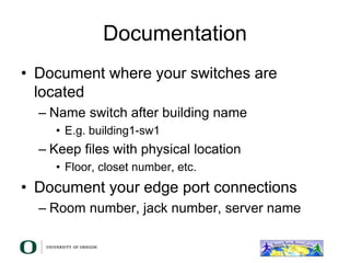
This document discusses layer 2 network design concepts. It recommends designing networks hierarchically with core, distribution, and access layers for modularity and scalability. Switches are preferred over hubs as they reduce collision domains. Routers further reduce broadcast domains. VLANs and link aggregation can increase network capacity and redundancy. Care must be taken to avoid switching loops which can cause broadcast storms. The guidelines emphasize building networks incrementally as needs grow.
This document provides an overview of campus network design concepts including hierarchical network structures, traffic domains, Ethernet protocols and technologies, and design best practices. Key points include:
- Campus networks should be designed hierarchically with core, distribution, and access layers to provide scalability and modularity.
- Switches reduce collision domains while routers reduce broadcast domains to optimize traffic flow and network performance.
- Ethernet, VLANs, trunking, link aggregation, and avoiding switching loops are important concepts for segmenting and connecting switches in a campus network.
- Best practices include building networks incrementally, connecting elements hierarchically, and avoiding non-modular designs like daisy-chaining or VLAN spaghetti
Networking devices can be categorized into five groups based on the OSI layer in which they operate: hubs, repeaters, bridges, routers, and gateways. Hubs and repeaters operate at the physical layer, bridges operate at the data link layer, and routers and gateways operate at the network layer or above. Bridges connect local area networks (LANs) by filtering and forwarding traffic between them based on MAC addresses, while routers connect LANs and wide area networks by routing packets based on logical network layer addresses.
This document discusses different types of networking devices used to connect local area networks (LANs). It describes hubs, repeaters, bridges, routers, and gateways. Hubs and repeaters operate at the physical layer, bridges operate at the physical and data link layers, and routers and gateways operate at the network layer and above to connect multiple networks and perform protocol conversion. The document provides details on the functions and characteristics of each type of device.
Network devices such as repeaters, hubs, bridges, switches, routers, and gateways are used to connect, expand, and manage network traffic. They operate at different layers of the OSI model from the physical layer to the network layer. Repeaters and hubs operate at the physical layer and broadcast traffic to all ports. Bridges segment networks at the data link layer by filtering traffic based on MAC addresses. Switches further improve segmentation by opening virtual circuits between connected devices. Routers connect multiple networks and use IP addresses to choose the best path at the network layer.
This document provides an overview of local area networks (LANs) and discusses various LAN topics including common topologies (bus, ring, star), frame transmission methods, the roles of hubs and switches, and how bridges and routers can be used to interconnect multiple LANs. It describes the three main layers (physical, media access control, logical link control) of the IEEE 802 LAN protocol architecture and compares it to the OSI model. Key concepts covered include shared medium access, the functions of bridges and switches, and how layer 2 switches improved upon earlier hub technologies to increase network capacity and performance.
Network devices serve several key functions:
1. Separating and connecting networks or expanding network capacity through devices like repeaters, hubs, bridges, routers, and switches.
2. Enabling remote access through modems and other technologies.
3. Key devices include repeaters which regenerate signals, bridges which understand node addresses, switches which divide networks into logical channels, and routers which interconnect networks and determine optimal routes. Remote access devices like modems modulate digital signals for transmission over telephone lines to connect distant computers.
Networking and Internetworking Devices21viveksingh
This document provides information on various networking and internetworking devices. It discusses hubs, which connect multiple networking cables together but do not amplify or filter signals. It covers bridges, which operate at the physical and data link layers to filter traffic between network segments. Routers are described as connecting LANs and WANs by routing packets based on logical addresses using routing tables. Gateways link different network types and protocols by translating between formats. Finally, switches and brouters are introduced, with switches offering intelligence beyond hubs to reduce congestion, and brouters combining routing and bridging capabilities.
This document provides an overview of local area networks (LANs) including common applications, architectures, topologies, transmission media, and protocols. Some key points:
1) LANs are used for personal computer networks, connecting large backend systems, high-speed office networks, storage area networks, and interconnecting multiple local networks.
2) Common topologies include bus, ring, star, and tree. Choices consider reliability, expandability, performance and the physical layout/medium.
3) Important protocols are Ethernet at the data link layer and IEEE 802 standards for physical and MAC sublayers which define frame formats and media access control.
This document provides an overview of local area networks (LANs) including common applications, architectures, topologies, transmission media, and protocols. Some key points:
1) LANs are used for personal computer networks, connecting large backend systems, high-speed office networks, storage area networks, and interconnecting multiple local networks.
2) Common topologies include bus, ring, star, and tree. Choices consider reliability, expandability, performance and the physical layout/medium.
3) Ethernet originally used coaxial cable but now focuses on twisted pair cabling. Fiber optic cables provide high speeds but are more expensive to install.
4) The protocol architecture includes the physical, data link
This document summarizes key points from Chapter 15 of William Stallings' book "Data and Computer Communications", 7th Edition. It discusses the applications and architectures of local area networks (LANs). The main applications covered are personal computer LANs, back-end networks, storage area networks, and high-speed office networks. Common LAN topologies like bus, ring, star and their characteristics are explained. Issues around transmission media, protocols, and network devices like bridges, hubs and switches are also summarized at a high level.
Network devices like repeaters, hubs, bridges, switches and routers are used to extend and segment networks. Repeaters regenerate signals to increase cable length while hubs connect cables without regeneration. Bridges segment networks at the data link layer using MAC addresses. Switches increase performance by opening virtual circuits between devices. Routers connect multiple networks at the network layer using IP addresses and dynamic routing.
The document provides an overview of wireless networks and wireless communication technologies. It discusses the key elements of a wireless network including wireless hosts, base stations, wireless links, infrastructure and ad hoc modes. It also covers wireless link characteristics such as signal attenuation, interference and multipath propagation. Finally, it introduces common wireless network standards and protocols including IEEE 802.11 wireless LANs, wireless network characteristics such as the hidden terminal problem, and wireless multiple access protocols.
Network devices like repeaters, hubs, bridges, switches, wireless access points, and routers were discussed.
Repeaters and hubs operate at the physical layer and broadcast signals to all ports. Bridges and switches operate at the data link layer and can filter traffic between specific ports based on MAC addresses. Wireless access points allow devices to connect to a network without wires. Network interface cards install into devices to connect them to a network. Routers operate at the network layer and can connect multiple networks and select the best path for traffic between networks.
Packet Switching Technique in Computer NetworkNiharikaDubey17
This document discusses different packet switching paradigms including virtual circuit switching, datagram switching, and source routing. It describes how bridges and extended local area networks (LANs) connect multiple LANs using a spanning tree algorithm to prevent loops. Finally, it covers limitations of bridges and how virtual LANs (VLANs) increase scalability and security by separating broadcast domains.
This document discusses local area networks (LANs) and their applications, architectures, and technologies. It covers:
1) Common LAN applications like personal computer networks, back-end networks, storage area networks, and high-speed office networks.
2) Key aspects of LAN architecture including topology (e.g. bus, star, ring), transmission medium, IEEE 802 standards, and the functions of bridges and switches.
3) Protocol architectures with descriptions of the physical, logical link control, and media access control layers, as well as common frame formats.
The document discusses layer 2 network design concepts. It describes a hierarchical network design with core, distribution, and access layers. It covers layer 2 protocols like Ethernet and switches, and how switches reduce collision domains compared to hubs. The document also covers VLANs, how they segment broadcast domains, and how VLAN traffic can cross switches using 802.1Q trunking. Finally, it discusses link aggregation using LACP for increased bandwidth or redundancy.
This document provides an overview of local area networks (LANs) and virtual LANs (VLANs). It defines LAN as a network covering a small area like a home, office or campus to connect computers in close proximity. The document discusses common LAN topologies like bus, ring and star. It then introduces VLAN as a way to logically segment devices within a LAN even if they share the same infrastructure. The document explains how VLANs work using tags and trunking between switches. It outlines benefits of VLANs like improved security, flexibility and traffic management compared to traditional LANs.
This document provides an overview of various network hardware components including repeaters, hubs, bridges, switches, routers, and gateways. It describes each component, what layer of the OSI model they operate at, their purpose, and key differences. Repeaters and hubs operate at the physical layer and regenerate and amplify signals. Bridges and switches operate at the data link layer and can filter and forward data to specific ports. Routers operate at the network layer and use IP addresses to route packets between networks. Gateways can operate at any layer and connect different network types.
This document discusses various network devices and their functions. It describes repeaters, routers, brouters, hubs, switches, bridges, network interface cards (NICs), and gateways. Repeaters operate at the physical layer and regenerate signals to extend network distance. Routers operate at multiple layers and direct traffic between networks by maintaining routing tables. Bridges separate networks into segments to reduce congestion. Switches operate at the data link layer to limit collision domains. NICs connect devices to the network. Gateways connect different network types and protocols.
Network devices such as repeaters, hubs, bridges, switches, routers, and gateways are used to extend and segment computer networks. Repeaters regenerate signals to increase network distance while hubs connect multiple cables but do not segment traffic. Bridges and switches segment networks into broadcast domains to reduce collisions. Routers connect different network types, choose optimal paths, and prevent broadcast traffic between segments. Gateways translate between different network protocols.
The document discusses the differences between hubs, switches, bridges and routers. Hubs operate at the physical layer using broadcasting, while switches are intelligent devices that operate at the data link layer using MAC addresses to reduce broadcasting. Spanning tree protocol is used to prevent loops when there are redundant links between switches by blocking certain ports.
1. Bridges separate collision domains and allow communication between different network segments by learning MAC addresses and only forwarding frames to their destination segment.
2. Switches operate similarly to bridges but only support a single frame type like Ethernet, and can provide faster switching through methods like store-and-forward.
3. Bridges and switches extend network reach and reduce congestion compared to repeaters, but precautions must be taken to prevent loops using spanning tree protocols.
This document provides an overview of network devices and protocols including repeaters, bridges, routers, gateways, TCP/IP, and applications like DNS, SMTP, HTTP. It describes the functions of repeaters, hubs, bridges, switches, routers, and gateways. Repeaters extend network length while hubs connect multiple devices. Bridges and switches filter traffic between segments/ports. Routers route packets between networks and gateways translate between different protocols. It also summarizes the layers of the TCP/IP protocol suite including network interface, internet, transport, and application layers, and describes protocols like IPv4, IPv6, TCP, UDP, and applications like DNS, SMTP, HTTP.
Network devices like hubs, switches, and routers are used to connect devices in a local area network (LAN). [1] Hubs split signals to multiple ports but do not extend cable length or regenerate signals, while active hubs do regenerate signals. [2] Switches are multi-port bridges that operate at the data link layer and use MAC addresses to create temporary paths between networked devices. Routers operate at the network layer and interconnect network segments or entire networks by examining packet addresses and choosing the best path through their internal routing tables.
Next-generation networks are becoming more complex and must support global workforces, legacy devices, and integrated voice, video, and data. Cisco's borderless network architecture addresses these challenges through a hierarchical design with core, distribution, and access layers that provide modularity, resiliency, and flexibility. Ethernet switches establish separate collision domains and extend broadcast domains, so network design must minimize broadcasts to prevent congestion.
A virtual local area network (VLAN) is a group of hosts with a common set of requirements that communicate as if they were attached to the same broadcast domain regardless of their physical location
Generating privacy-protected synthetic data using Secludy and MilvusZilliz
During this demo, the founders of Secludy will demonstrate how their system utilizes Milvus to store and manipulate embeddings for generating privacy-protected synthetic data. Their approach not only maintains the confidentiality of the original data but also enhances the utility and scalability of LLMs under privacy constraints. Attendees, including machine learning engineers, data scientists, and data managers, will witness first-hand how Secludy's integration with Milvus empowers organizations to harness the power of LLMs securely and efficiently.
Fueling AI with Great Data with Airbyte WebinarZilliz
This talk will focus on how to collect data from a variety of sources, leveraging this data for RAG and other GenAI use cases, and finally charting your course to productionalization.
Trusted Execution Environment for Decentralized Process MiningLucaBarbaro3
Presentation of the paper "Trusted Execution Environment for Decentralized Process Mining" given during the CAiSE 2024 Conference in Cyprus on June 7, 2024.
Driving Business Innovation: Latest Generative AI Advancements & Success StorySafe Software
Are you ready to revolutionize how you handle data? Join us for a webinar where we’ll bring you up to speed with the latest advancements in Generative AI technology and discover how leveraging FME with tools from giants like Google Gemini, Amazon, and Microsoft OpenAI can supercharge your workflow efficiency.
During the hour, we’ll take you through:
Guest Speaker Segment with Hannah Barrington: Dive into the world of dynamic real estate marketing with Hannah, the Marketing Manager at Workspace Group. Hear firsthand how their team generates engaging descriptions for thousands of office units by integrating diverse data sources—from PDF floorplans to web pages—using FME transformers, like OpenAIVisionConnector and AnthropicVisionConnector. This use case will show you how GenAI can streamline content creation for marketing across the board.
Ollama Use Case: Learn how Scenario Specialist Dmitri Bagh has utilized Ollama within FME to input data, create custom models, and enhance security protocols. This segment will include demos to illustrate the full capabilities of FME in AI-driven processes.
Custom AI Models: Discover how to leverage FME to build personalized AI models using your data. Whether it’s populating a model with local data for added security or integrating public AI tools, find out how FME facilitates a versatile and secure approach to AI.
We’ll wrap up with a live Q&A session where you can engage with our experts on your specific use cases, and learn more about optimizing your data workflows with AI.
This webinar is ideal for professionals seeking to harness the power of AI within their data management systems while ensuring high levels of customization and security. Whether you're a novice or an expert, gain actionable insights and strategies to elevate your data processes. Join us to see how FME and AI can revolutionize how you work with data!
5th LF Energy Power Grid Model Meet-up SlidesDanBrown980551
5th Power Grid Model Meet-up
It is with great pleasure that we extend to you an invitation to the 5th Power Grid Model Meet-up, scheduled for 6th June 2024. This event will adopt a hybrid format, allowing participants to join us either through an online Mircosoft Teams session or in person at TU/e located at Den Dolech 2, Eindhoven, Netherlands. The meet-up will be hosted by Eindhoven University of Technology (TU/e), a research university specializing in engineering science & technology.
Power Grid Model
The global energy transition is placing new and unprecedented demands on Distribution System Operators (DSOs). Alongside upgrades to grid capacity, processes such as digitization, capacity optimization, and congestion management are becoming vital for delivering reliable services.
Power Grid Model is an open source project from Linux Foundation Energy and provides a calculation engine that is increasingly essential for DSOs. It offers a standards-based foundation enabling real-time power systems analysis, simulations of electrical power grids, and sophisticated what-if analysis. In addition, it enables in-depth studies and analysis of the electrical power grid’s behavior and performance. This comprehensive model incorporates essential factors such as power generation capacity, electrical losses, voltage levels, power flows, and system stability.
Power Grid Model is currently being applied in a wide variety of use cases, including grid planning, expansion, reliability, and congestion studies. It can also help in analyzing the impact of renewable energy integration, assessing the effects of disturbances or faults, and developing strategies for grid control and optimization.
What to expect
For the upcoming meetup we are organizing, we have an exciting lineup of activities planned:
-Insightful presentations covering two practical applications of the Power Grid Model.
-An update on the latest advancements in Power Grid -Model technology during the first and second quarters of 2024.
-An interactive brainstorming session to discuss and propose new feature requests.
-An opportunity to connect with fellow Power Grid Model enthusiasts and users.
zkStudyClub - LatticeFold: A Lattice-based Folding Scheme and its Application...Alex Pruden
Folding is a recent technique for building efficient recursive SNARKs. Several elegant folding protocols have been proposed, such as Nova, Supernova, Hypernova, Protostar, and others. However, all of them rely on an additively homomorphic commitment scheme based on discrete log, and are therefore not post-quantum secure. In this work we present LatticeFold, the first lattice-based folding protocol based on the Module SIS problem. This folding protocol naturally leads to an efficient recursive lattice-based SNARK and an efficient PCD scheme. LatticeFold supports folding low-degree relations, such as R1CS, as well as high-degree relations, such as CCS. The key challenge is to construct a secure folding protocol that works with the Ajtai commitment scheme. The difficulty, is ensuring that extracted witnesses are low norm through many rounds of folding. We present a novel technique using the sumcheck protocol to ensure that extracted witnesses are always low norm no matter how many rounds of folding are used. Our evaluation of the final proof system suggests that it is as performant as Hypernova, while providing post-quantum security.
Paper Link: https://eprint.iacr.org/2024/257
Digital Banking in the Cloud: How Citizens Bank Unlocked Their MainframePrecisely
Inconsistent user experience and siloed data, high costs, and changing customer expectations – Citizens Bank was experiencing these challenges while it was attempting to deliver a superior digital banking experience for its clients. Its core banking applications run on the mainframe and Citizens was using legacy utilities to get the critical mainframe data to feed customer-facing channels, like call centers, web, and mobile. Ultimately, this led to higher operating costs (MIPS), delayed response times, and longer time to market.
Ever-changing customer expectations demand more modern digital experiences, and the bank needed to find a solution that could provide real-time data to its customer channels with low latency and operating costs. Join this session to learn how Citizens is leveraging Precisely to replicate mainframe data to its customer channels and deliver on their “modern digital bank” experiences.
Best 20 SEO Techniques To Improve Website Visibility In SERPPixlogix Infotech
Boost your website's visibility with proven SEO techniques! Our latest blog dives into essential strategies to enhance your online presence, increase traffic, and rank higher on search engines. From keyword optimization to quality content creation, learn how to make your site stand out in the crowded digital landscape. Discover actionable tips and expert insights to elevate your SEO game.
This presentation provides valuable insights into effective cost-saving techniques on AWS. Learn how to optimize your AWS resources by rightsizing, increasing elasticity, picking the right storage class, and choosing the best pricing model. Additionally, discover essential governance mechanisms to ensure continuous cost efficiency. Whether you are new to AWS or an experienced user, this presentation provides clear and practical tips to help you reduce your cloud costs and get the most out of your budget.
Monitoring and Managing Anomaly Detection on OpenShift.pdfTosin Akinosho
Monitoring and Managing Anomaly Detection on OpenShift
Overview
Dive into the world of anomaly detection on edge devices with our comprehensive hands-on tutorial. This SlideShare presentation will guide you through the entire process, from data collection and model training to edge deployment and real-time monitoring. Perfect for those looking to implement robust anomaly detection systems on resource-constrained IoT/edge devices.
Key Topics Covered
1. Introduction to Anomaly Detection
- Understand the fundamentals of anomaly detection and its importance in identifying unusual behavior or failures in systems.
2. Understanding Edge (IoT)
- Learn about edge computing and IoT, and how they enable real-time data processing and decision-making at the source.
3. What is ArgoCD?
- Discover ArgoCD, a declarative, GitOps continuous delivery tool for Kubernetes, and its role in deploying applications on edge devices.
4. Deployment Using ArgoCD for Edge Devices
- Step-by-step guide on deploying anomaly detection models on edge devices using ArgoCD.
5. Introduction to Apache Kafka and S3
- Explore Apache Kafka for real-time data streaming and Amazon S3 for scalable storage solutions.
6. Viewing Kafka Messages in the Data Lake
- Learn how to view and analyze Kafka messages stored in a data lake for better insights.
7. What is Prometheus?
- Get to know Prometheus, an open-source monitoring and alerting toolkit, and its application in monitoring edge devices.
8. Monitoring Application Metrics with Prometheus
- Detailed instructions on setting up Prometheus to monitor the performance and health of your anomaly detection system.
9. What is Camel K?
- Introduction to Camel K, a lightweight integration framework built on Apache Camel, designed for Kubernetes.
10. Configuring Camel K Integrations for Data Pipelines
- Learn how to configure Camel K for seamless data pipeline integrations in your anomaly detection workflow.
11. What is a Jupyter Notebook?
- Overview of Jupyter Notebooks, an open-source web application for creating and sharing documents with live code, equations, visualizations, and narrative text.
12. Jupyter Notebooks with Code Examples
- Hands-on examples and code snippets in Jupyter Notebooks to help you implement and test anomaly detection models.
How to Interpret Trends in the Kalyan Rajdhani Mix Chart.pdfChart Kalyan
A Mix Chart displays historical data of numbers in a graphical or tabular form. The Kalyan Rajdhani Mix Chart specifically shows the results of a sequence of numbers over different periods.
Building Production Ready Search Pipelines with Spark and MilvusZilliz
Spark is the widely used ETL tool for processing, indexing and ingesting data to serving stack for search. Milvus is the production-ready open-source vector database. In this talk we will show how to use Spark to process unstructured data to extract vector representations, and push the vectors to Milvus vector database for search serving.
Dandelion Hashtable: beyond billion requests per second on a commodity serverAntonios Katsarakis
This slide deck presents DLHT, a concurrent in-memory hashtable. Despite efforts to optimize hashtables, that go as far as sacrificing core functionality, state-of-the-art designs still incur multiple memory accesses per request and block request processing in three cases. First, most hashtables block while waiting for data to be retrieved from memory. Second, open-addressing designs, which represent the current state-of-the-art, either cannot free index slots on deletes or must block all requests to do so. Third, index resizes block every request until all objects are copied to the new index. Defying folklore wisdom, DLHT forgoes open-addressing and adopts a fully-featured and memory-aware closed-addressing design based on bounded cache-line-chaining. This design offers lock-free index operations and deletes that free slots instantly, (2) completes most requests with a single memory access, (3) utilizes software prefetching to hide memory latencies, and (4) employs a novel non-blocking and parallel resizing. In a commodity server and a memory-resident workload, DLHT surpasses 1.6B requests per second and provides 3.5x (12x) the throughput of the state-of-the-art closed-addressing (open-addressing) resizable hashtable on Gets (Deletes).
Let's Integrate MuleSoft RPA, COMPOSER, APM with AWS IDP along with Slackshyamraj55
Discover the seamless integration of RPA (Robotic Process Automation), COMPOSER, and APM with AWS IDP enhanced with Slack notifications. Explore how these technologies converge to streamline workflows, optimize performance, and ensure secure access, all while leveraging the power of AWS IDP and real-time communication via Slack notifications.
Let's Integrate MuleSoft RPA, COMPOSER, APM with AWS IDP along with Slack
layer2-network-design.ppt
1. Layer 2 Network Design
Carlos Vicente
University of Oregon
cvicente@uoregon.edu
2. Campus Network Design - Review
• A good network design is modular and
hierarchical, with a clear separation of
functions:
– Core: Resilient, few changes, few features,
high bandwidth, CPU power
– Distribution: Aggregation, redundancy
– Access: Port density, affordability, security
features, many adds, moves and changes
5. In-Building and Layer 2
• There is usually a correspondence between
building separation and subnet separation
– Switching inside a building
– Routing between buildings
• This will depend on the size of the network
– Very small networks can get by with doing switching
between buildings
– Very large networks might need to do routing inside
buildings
6. Layer 2 Concepts
• Layer 2 protocols basically control access
to a shared medium (copper, fiber, electro-
magnetic waves)
• Ethernet is the de-facto standard today
– Reasons:
• Simple
• Cheap
• Manufacturers keep making it faster
7. Ethernet Functions
• Source and Destination identification
– MAC addresses
• Detect and avoid frame collisions
– Listen and wait for channel to be available
– If collision occurs, wait a random period
before retrying
• This is called CASMA-CD: Carrier Sense Multiple
Access with Collision Detection
8. Ethernet Frame
• SFD = Start of Frame Delimiter
• DA = Destination Address
• SA = Source Address
• CRC = Cyclick Redundancy Check
9. Evolution of Ethernet
Topologies
• Bus
– Everybody on the same coaxial cable
• Star
– One central device connects every other node
• First with hubs (repeated traffic)
• Later with switches (bridged traffic)
– Structured cabling for star topologies
standardized
10. Switched Star Topology
Benefits
• It’s modular:
– Independent wires for each end node
– Independent traffic in each wire
– A second layer of switches can be added to
build a hierarchical network that extends the
same two benefits above
– ALWAYS DESIGN WITH MODULARITY IN
MIND
11. Hub
• Receives a frame on one port and sends it
out every other port, always.
• Collision domain is not reduced
• Traffic ends up in places where it’s not
needed
12. Hub
Hub
A frame sent by one node is always sent to every other node.
Hubs are also called “repeaters” because they just “repeat”
what they hear.
13. Switch
• Learns the location of each node by
looking at the source address of each
incoming frame, and builds a forwarding
table
• Forwards each incoming frame to the port
where the destination node is
– Reduces the collision domain
– Makes more efficient use of the wire
– Nodes don’t waste time checking frames not destined to
them
15. Switches and Broadcast
• A switch broadcasts some frames:
– When the destination address is not found in
the table
– When the frame is destined to the broadcast
address (FF:FF:FF:FF:FF:FF)
– When the frame is destined to a multicast
ethernet address
• So, switches do not reduce the broadcast
domain!
16. Switch vs. Router
• Routers more or less do with IP packets what
switches do with Ethernet frames
– A router looks at the IP packet destination and checks
its routing table to decide where to forward the
packet
• Some differences:
– IP packets travel inside ethernet frames
– IP networks can be logically segmented into subnets
– Switches do not usually know about IP, they only deal
with Ethernet frames
17. Switch vs. Router
• Routers do not forward Ethernet
broadcasts. So:
– Switches reduce the collision domain
– Routers reduce the broadcast domain
• This becomes really important when trying
to design hierarchical, scalable networks
that can grow sustainably
19. Traffic Domains
• Try to eliminate collision domains
– Get rid of hubs!
• Try to keep your broadcast domain limited
to no more than 250 simultaneously
connected hosts
– Segment your network using routers
20. Layer 2 Network Design Guidelines
• Always connect hierarchically
– If there are multiple switches in a building, use
an aggregation switch
– Locate the aggregation switch close to the
building entry point (e.g. fiber panel)
– Locate edge switches close to users (e.g. one
per floor)
• Max length for Cat 5 is 100 meters
28. Virtual LANs (VLANs)
• Allow us to split switches into separate
(virtual) switches
• Only members of a VLAN can see that
VLAN’s traffic
– Inter-vlan traffic must go through a router
29. Local VLANs
• 2 VLANs or more within a single switch
• Edge ports, where end nodes are
connected, are configured as members of
a VLAN
• The switch behaves as several virtual
switches, sending traffic only within VLAN
members
31. VLANs across switches
• Two switches can exchange traffic from
one or more VLANs
• Inter-switch links are configured as
trunks, carrying frames from all or a
subset of a switch’s VLANs
• Each frame carries a tag that identifies
which VLAN it belongs to
32. 802.1Q
• The IEEE standard that defines how
ethernet frames should be tagged when
moving across switch trunks
• This means that switches from different
vendors are able to exchange VLAN
traffic.
34. VLANs across switches
802.1Q Trunk
Tagged Frames
VLAN X VLAN Y
VLAN X VLAN Y
Edge Ports
Trunk Port
This is called “VLAN Trunking”
35. Tagged vs. Untagged
• Edge ports are not tagged, they are just
“members” of a VLAN
• You only need to tag frames in switch-to-
switch links (trunks), when transporting
multiple VLANs
• A trunk can transport both tagged and
untagged VLANs
– As long as the two switches agree on how to
handle those
36. VLANS increase complexity
• You can no longer “just replace” a switch
– Now you have VLAN configuration to maintain
– Field technicians need more skills
• You have to make sure that all the switch-
to-switch trunks are carrying all the
necessary VLANs
– Need to keep in mind when adding/removing
VLANs
37. Good reasons to use VLANs
• You want to segment your network into
multiple subnets, but can’t buy enough
switches
– Hide sensitive infrastructure like IP phones,
building controls, etc.
• Separate control traffic from user traffic
– Restrict who can access your switch
management address
38. Bad reasons to use VLANs
• Because you can, and you feel cool
• Because they will completely secure your
hosts (or so you think)
• Because they allow you to extend the
same IP network over multiple separate
buildings
39. Do not build “VLAN spaghetti”
• Extending a VLAN to multiple buildings
across trunk ports
• Bad idea because:
– Broadcast traffic is carried across all trunks
from one end of the network to another
– Broadcast storm can spread across the extent
of the VLAN
– Maintenance and troubleshooting nightmare
40. Link Aggregation
• Also known as port bundling, link bundling
• You can use multiple links in parallel as a single,
logical link
– For increased capacity
– For redundancy (fault tolerance)
• LACP (Link Aggregation Control Protocol) is a
standardized method of negotiating these
bundled links between switches
41. LACP Operation
• Two switches connected via multiple links
will send LACPDU packets, identifying
themselves and the port capabilities
• They will then automatically build the
logical aggregated links, and then pass
traffic.
• Switche ports can be configured as active
or passive
42. LACP Operation
Switch A Switch B
LACPDUs
• Switches A and B are connected to each other using two sets of Fast
Ethernet ports
• LACP is enabled and the ports are turned on
• Switches start sending LACPDUs, then negotiate how to set up the
aggregation
100 Mbps
100 Mbps
43. LACP Operation
200 Mbps logical link
• The result is an aggregated 200 Mbps logical link
• The link is also fault tolerant: If one of the member links fail, LACP will
automatically take that link off the bundle, and keep sending traffic over
the remaining link
Switch A Switch B
100 Mbps
100 Mbps
44. Distributing Traffic
in Bundled Links
• Bundled links distribute frames using a
hashing algorithm, based on:
– Source and/or Destination MAC address
– Source and/or Destination IP address
– Source and/or Destination Port numbers
• This can lead to unbalanced use of the
links, depending on the nature of the traffic
• Always choose the load-balancing method
that provides the most distribution
45. Switching Loop
Switch A Switch B
Swtich C
• When there is more than
one path between two
switches
• What are the potential
problems?
46. Switching Loop
• If there is more than one path between two
switches:
– Forwarding tables become unstable
• Source MAC addresses are repeatedly seen
coming from different ports
– Switches will broadcast each other’s
broadcasts
• All available bandwidth is utilized
• Switch processors cannot handle the load
47. Switching Loop
Switch A Switch B
Swtich C
• Node1 sends a broadcast
frame (e.g. an ARP request)
Node 1
48. Switching Loop
Switch A Switch B
Swtich C
• Switches A, B and C
broadcast node 1’s
frame out every port
Node 1
49. Switching Loop
Switch A Switch B
Swtich C
• But they receive
each other’s
broadcasts, which
they need to forward
again out every port!
•The broadcasts are
amplified, creating a
broadcast storm
Node 1
50. Good Switching Loops
• But you can take advantage of loops!
– Redundant paths improve resilience when:
• A switch fails
• Wiring breaks
• How to achieve redundancy without
creating dangerous traffic loops?
51. What is a Spanning Tree
• “Given a connected,
undirected graph, a
spanning tree of that
graph is a subgraph
which is a tree and
connects all the vertices
together”.
• A single graph can have
many different spanning
trees.
52. Spanning Tree Protocol
• The purpose of the protocol is to have
bridges dynamically discover a subset of
the topology that is loop-free (a tree) and
yet has just enough connectivity so that
where physically possible, there is a path
between every switch
53. Spanning Tree Protocol
• Several flavors:
– Traditional Spanning Tree (802.1d)
– Rapid Spanning Tree or RSTP (802.1w)
– Multiple Spanning Tree or MSTP (802.1s)
54. Traditional Spanning Tree (802.1d)
• Switches exchange messages that allow
them to compute the Spanning Tree
– These messages are called BPDUs (Bridge
Protocol Data Units)
– Two types of BPDUs:
• Configuration
• Topology Change Notification (TCN)
55. Traditional Spanning Tree (802.1d)
• First Step:
– Decide on a point of reference: the Root
Bridge
– The election process is based on the Bridge
ID, which is composed of:
• The Bridge Priority: A two-byte value that is
configurable
• The MAC address: A unique, hardcoded address
that cannot be changed.
56. Root Bridge Selection (802.1d)
• Each switch starts by sending out BPDUs with a
Root Bridge ID equal to its own Bridge ID
– I am the root!
• Received BPDUs are analyzed to see if a lower
Root Bridge ID is being announced
– If so, each switch replaces the value of the advertised
Root Bridge ID with this new lower ID
• Eventually, they all agree on who the Root
Bridge is
57. Root Bridge Selection (802.1d)
Switch B Switch C
Swtich A
32678.0000000000AA
32678.0000000000BB 32678.0000000000CC
• All switches have the same priority.
• Who is the elected root bridge?
58. Root Port Selection (802.1d)
• Now each switch needs to figure out
where it is in relation to the Root Bridge
– Each switch needs to determine its Root Port
– The key is to find the port with the lowest
Root Path Cost
• The cumulative cost of all the links leading to the
Root Bridge
59. Root Port Selection (802.1d)
• Each link on a switch has a Path Cost
– Inversely proportional to the link speed
• e.g. The faster the link, the lower the cost
Link Speed STP Cost
10 Mbps 100
100 Mbps 19
1 Gbps 4
10 Gbps 2
60. Root Port Selection (802.1d)
• Root Path Cost is the accumulation of a
link’s Path Cost and the Path Costs
learned from neighboring Switches.
– It answers the question: How much does it
cost to reach the Root Bridge through this
port?
61. Root Port Selection (802.1d)
1. Root Bridge sends out BPDUs with a
Root Path Cost value of 0
2. Neighbor receives BPDU and adds port’s
Path Cost to Root Path Cost received
3. Neighbor sends out BPDUs with new
cumulative value as Root Path Cost
4. Other neighbor’s down the line keep
adding in the same fashion
62. Root Port Selection (802.1d)
• On each switch, the port where the lowest
Root Path Cost was received becomes the
Root Port
– This is the port with the best path to the Root
Bridge
63. Root Port Selection (802.1d)
Switch B Switch C
Swtich A
1 2
1 1
2 2
Cost=19 Cost=19
Cost=19
32678.0000000000AA
32678.0000000000BB 32678.0000000000CC
• What is the Path Cost on each Port?
• What is the Root Port on each switch?
64. Root Port Selection (802.1d)
Switch B Switch C
Swtich A
1 2
1 1
2 2
Cost=19 Cost=19
Cost=19
32678.0000000000AA
32678.0000000000BB 32678.0000000000CC
Root Port
Root Port
65. Electing Designated Ports (802.1d)
• OK, we now have selected root ports but we
haven’t solved the loop problem yet, have we
– The links are still active!
• Each network segment needs to have only
one switch forwarding traffic to and from
that segment
• Switches then need to identify one Designated
Port per link
– The one with the lowest cumulative Root Path Cost to
the Root Bridge
66. Electing Designated Ports(802.1d)
• Which port should be the Designated Port
on each segment?
Switch B Switch C
Swtich A
1 2
1 1
2 2
Cost=19 Cost=19
Cost=19
32678.0000000000AA
32678.0000000000BB 32678.0000000000CC
67. Electing Designated Ports (802.1d)
• Two or more ports in a segment having identical
Root Path Costs is possible, which results in a
tie condition
• All STP decisions are based on the following
sequence of conditions:
– Lowest Root Bridge ID
– Lowest Root Path Cost to Root Bridge
– Lowest Sender Bridge ID
– Lowest Sender Port ID
68. Electing Designated Ports(802.1d)
Switch B Switch C
Swtich A
1 2
1 1
2 2
Cost=19 Cost=19
Cost=19
32678.0000000000AA
32678.0000000000BB 32678.0000000000CC
Designated
Port
Designated
Port
Designated
Port
In the B-C link, Switch B has the lowest
Bridge ID, so port 2 in Switch B is the
Designated Port
69. Blocking a port
• Any port that is not elected as either a
Root Port, nor a Designated Port is put
into the Blocking State.
• This step effectively breaks the loop and
completes the Spanning Tree.
70. Designated Ports on each segment (802.1d)
Switch B Switch C
Swtich A
1 2
1 1
2 2
Cost=19 Cost=19
Cost=19
32678.0000000000AA
32678.0000000000BB 32678.0000000000CC
• Port 2 in Switch C is then put into the Blocking State because it is
neither a Root Port nor a Designated Port
✕
71. Spanning Tree Protocol States
• Disabled
– Port is shut down
• Blocking
– Not forwarding frames
– Receiving BPDUs
• Listening
– Not forwarding frames
– Sending and receiving BPDUs
72. Spanning Tree Protocol States
• Learning
– Not forwarding frames
– Sending and receiving BPDUs
– Learning new MAC addresses
• Forwarding
– Forwarding frames
– Sending and receiving BPDUs
– Learning new MAC addresses
73. STP Topology Changes
• Switches will recalculate if:
– A new switch is introduced
• It could be the new Root Bridge!
– A switch fails
– A link fails
74. Root Bridge Placement
• Using default STP parameters might result
in an undesired situation
– Traffic will flow in non-optimal ways
– An unstable or slow switch might become the
root
• You need to plan your assignment of
bridge priorities carefully
75. Bad Root Bridge Placement
Switch B
Switch C
Swtich D
32678.0000000000DD 32678.0000000000BB
32678.0000000000CC Switch A 32678.0000000000AA
Root
Bridge
Out to router
76. Good Root Bridge Placement
Switch B
Switch C
Swtich D
1.0000000000DD 0.0000000000BB
32678.0000000000CC Switch A 32678.0000000000AA
Alernative
Root Bridge
Out to active
router
Root Bridge
Out to standby
router
77. Protecting the STP Topology
• Some vendors have included features that
protect the STP topology:
– Root Guard
– BPDU Guard
– Loop Guard
– UDLD
– Etc.
78. STP Design Guidelines
• Enable spanning tree even if you don’t
have redundant paths
• Always plan and set bridge priorities
– Make the root choice deterministic
– Include an alternative root bridge
• If possible, do not accept BPDUs on end
user ports
– Apply BPDU Guard or similar where available
79. 8021.d Convergence Speeds
• Moving from the Blocking state to the Forwarding State
takes at least 2 x Forward Delay time units (~ 30 secs.)
– This can be annoying when connecting end user stations
• Some vendors have added enhancements such as
PortFast, which will reduce this time to a minimum for
edge ports
– Never use PortFast or similar in switch-to-switch links
• Topology changes tipically take 30 seconds too
– This can be unacceptable in a production network
80. Rapid Spanning Tree (802.1w)
• Convergence is much faster
– Communication between switches is more
interactive
• Edge ports don’t participate
– Edge ports transition to forwarding state
immediately
– If BPDUs are received on an edge port, it
becomes a non-edge port to prevent loops
81. Rapid Spanning Tree (802.1w)
• Defines these port roles:
– Root Port (same as with 802.1d)
– Alternate Port
• A port with an alternate path to the root
– Designated Port (same as with 802.1d)
– Backup Port
• A backup/redundant path to a segment where
another bridge port already connects.
82. Rapid Spanning Tree (802.1w)
• Synchronization process uses a
handshake method
– After a root is elected, the topology is built in
cascade, where each switch proposes to be
the designated bridge for each point-to-point
link
– While this happens, all the downstream switch
links are blocking
83. Rapid Spanning Tree (802.1w)
Root
Switch
Proposal
Switch
Agreement
Switch
Switch
DP
RP
84. Rapid Spanning Tree (802.1w)
Root
Switch
Proposal
Switch
Agreement
Switch
Switch
DP
RP
DP
RP
85. Rapid Spanning Tree (802.1w)
Root
Switch
Proposal
Switch
Agreement
Switch
Switch
DP
RP
DP
RP
DP
RP
86. Rapid Spanning Tree (802.1w)
Root
Switch
Proposal
Switch
Agreement
Switch
Switch
DP
RP
DP
RP
DP
RP
DP
RP
87. Rapid Spanning Tree (802.1w)
• Prefer RSTP over STP if you want faster
convergence
• Always define which ports are edge ports
88. Multiple Spanning Tree (802.1s)
• Allows separate spanning trees per VLAN
group
– Different topologies allow for load balancing
between links
– Each group of VLANs are assigned to an
“instance” of MST
• Compatible with STP and RSTP
90. Multiple Spanning Tree (802.1s)
• MST Region
– Switches are members of a region if they
have the same set of attributes:
• MST configuration name
• MST configuration revision
• Instance-to-VLAN mapping
– A digest of these attributes is sent inside the
BPDUs for fast comparison by the switches
– One region is usually sufficient
91. Multiple Spanning Tree (802.1s)
• CST = Common Spanning Tree
– In order to interoperate with other versions of
Spanning Tree, MST needs a common tree
that contains all the other islands, including
other MST regions
92. Multiple Spanning Tree (802.1s)
• IST = Internal Spanning Tree
– Internal to the Region, that is
– Presents the entire region as a single virtual
bridge to the CST outside
93. Multiple Spanning Tree (802.1s)
• MST Instances
– Groups of VLANs are mapped to particular
Spanning Tree instances
– These instances will represent the alternative
topologies, or forwarding paths
– You specify a root and alternate root for each
instance
95. Multiple Spanning Tree (802.1s)
• Design Guidelines
– Determine relevant forwarding paths, and
distribute your VLANs equally into instances
matching these topologies
– Assign different root and alternate root
switches to each instance
– Make sure all switches match region
attributes
– Do not assign VLANs to instance 0, as this is
used by the IST
96. Selecting Switches
• Minimum features:
– Standards compliance
– Encrypted management (SSH/HTTPS)
– VLAN trunking
– Spanning Tree (RSTP at least)
– SNMP
• At least v2 (v3 has better security)
• Traps
97. Selecting Switches
• Other recommended features:
– DHCP Snooping
• Prevent end-users from running a rogue DHCP
server
– Happens a lot with little wireless routers (Netgear,
Linksys, etc) plugged in backwards
• Uplink ports towards the legitimate DHCP server
are defined as “trusted”. If DHCPOFFERs are
seen coming from any untrusted port, they are
dropped.
98. Selecting Switches
• Other recommended features:
– Dynamic ARP inspection
• A malicious host can perform a man-in-the-middle
attack by sending gratuitous ARP responses, or
responding to requests with bogus information
• Switches can look inside ARP packets and discard
gratuitous and invalid ARP packets.
99. Selecting Switches
• Other recommended features:
– IGMP Snooping:
• Switches normally flood multicast frames out every
port
• Snooping on IGMP traffic, the switch can learn
which stations are members of a multicast group,
thus forwarding multicast frames only out
necessary ports
• Very important when users run Norton Ghost, for
example.
100. Network Management
• Enable SNMP traps and/or syslog
– Collect and process in centralized log server
• Spanning Tree Changes
• Duplex mismatches
• Wiring problems
• Monitor configurations
– Use RANCID to report any changes in the
switch configuration
101. Network Management
• Collect forwarding tables with SNMP
– Allows you to find a MAC address in your
network quickly
– You can use simple text files + grep, or a web
tool with DB backend
• Enable LLDP (or CDP or similar)
– Shows how switches are connected to each
other and to other network devices
102. Documentation
• Document where your switches are
located
– Name switch after building name
• E.g. building1-sw1
– Keep files with physical location
• Floor, closet number, etc.
• Document your edge port connections
– Room number, jack number, server name