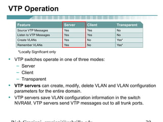
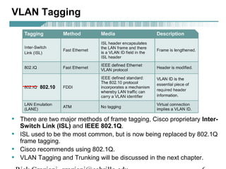
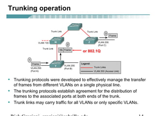
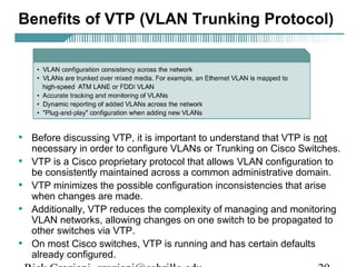
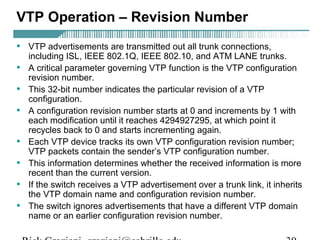
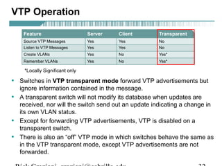
- VLAN Trunking Protocol (VTP) allows VLAN configurations to be consistently maintained across a common administrative domain to reduce complexity and inconsistencies when changes are made. VTP advertisements containing VLAN information are transmitted over trunk links and switches inherit the sending switch's VTP domain name. VTP uses revision numbers, starting at 0 and incrementing with each change, to determine if received information is more recent than the local configuration.

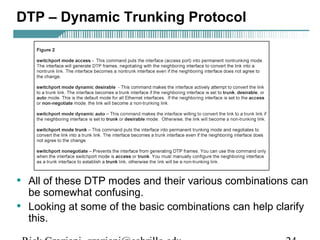
![Configuring Trunking
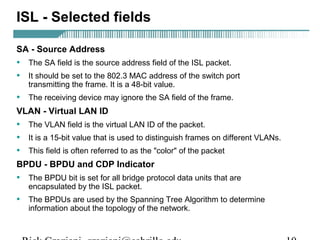
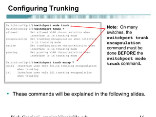
Switch(config-if)switchport trunk encapsulation [dot1q|isl]
• This command configures VLAN tagging on an interface.
• The two options are:
– dot1q – IEEE 802.1Q
– isl – ISL
• The tagging must be the same on both ends.
Rick Graziani graziani@cabrillo.edu 17](https://image.slidesharecdn.com/ccna3-mod9-vtp-141212233508-conversion-gate02/85/Ccna3-mod9-vtp-17-320.jpg)
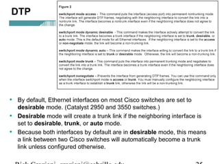
![Configuring Trunking
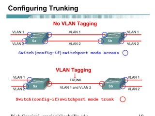
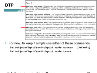
Switch(config-if)switchport mode [access|trunk]
• By default, 2900XL switchports are configured as “access” ports.
• An access port means that the port (interface) can only belong to a
single VLAN.
• Access ports are used when:
– Only a single device is connected to the port
– Multiple devices (hub) are connected to the port, all belonging to
the same VLAN
– Another switch is connected to this interface, but this link is only
carrying a single VLAN (non-trunk link).
• Trunk ports are used when:
– Another switch is connected to this interface, and this link is
carrying multiple VLANa (trunk link).
Rick Graziani graziani@cabrillo.edu 18](https://image.slidesharecdn.com/ccna3-mod9-vtp-141212233508-conversion-gate02/85/Ccna3-mod9-vtp-18-320.jpg)
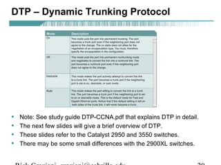
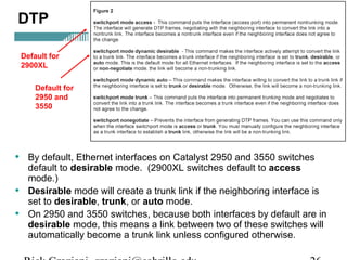
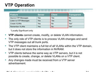
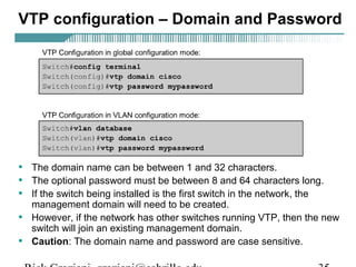
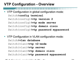
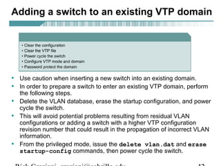
![VTP configuration – VTP mode
Switch#config terminal
Switch(config)#vtp mode [client|server|transparent]
Switch#vlan database
Switch(vlan)#vtp [client|server|transparent]
Rick Graziani graziani@cabrillo.edu 37](https://image.slidesharecdn.com/ccna3-mod9-vtp-141212233508-conversion-gate02/85/Ccna3-mod9-vtp-37-320.jpg)