Downloaded 103 times
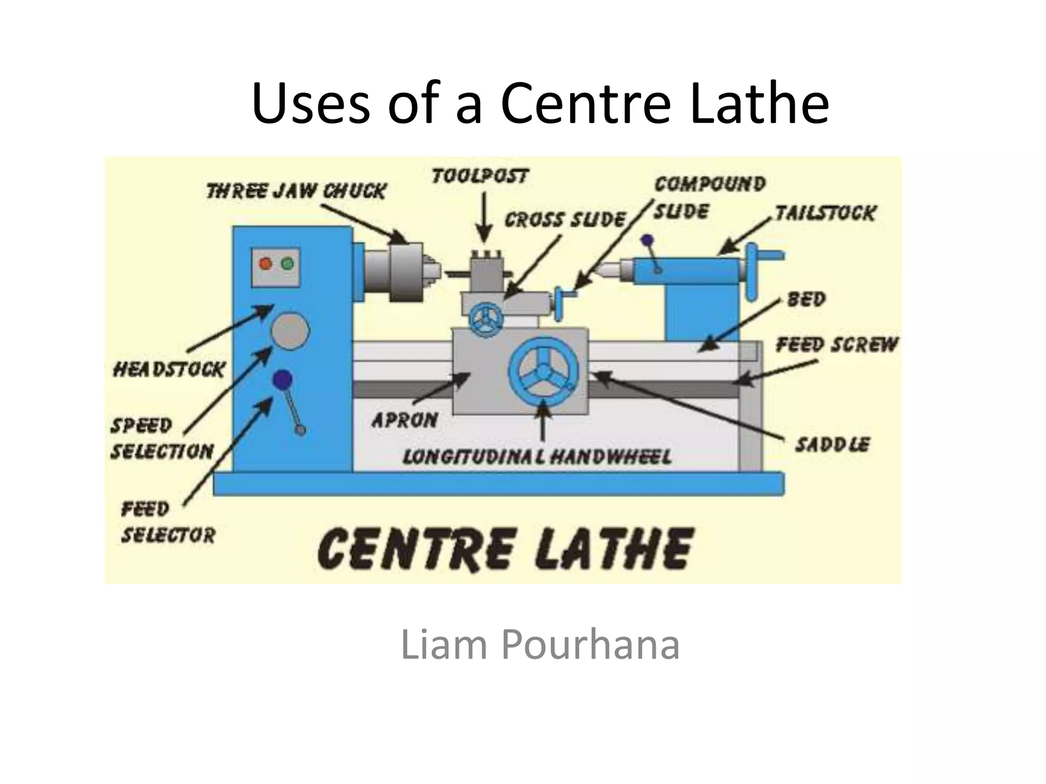
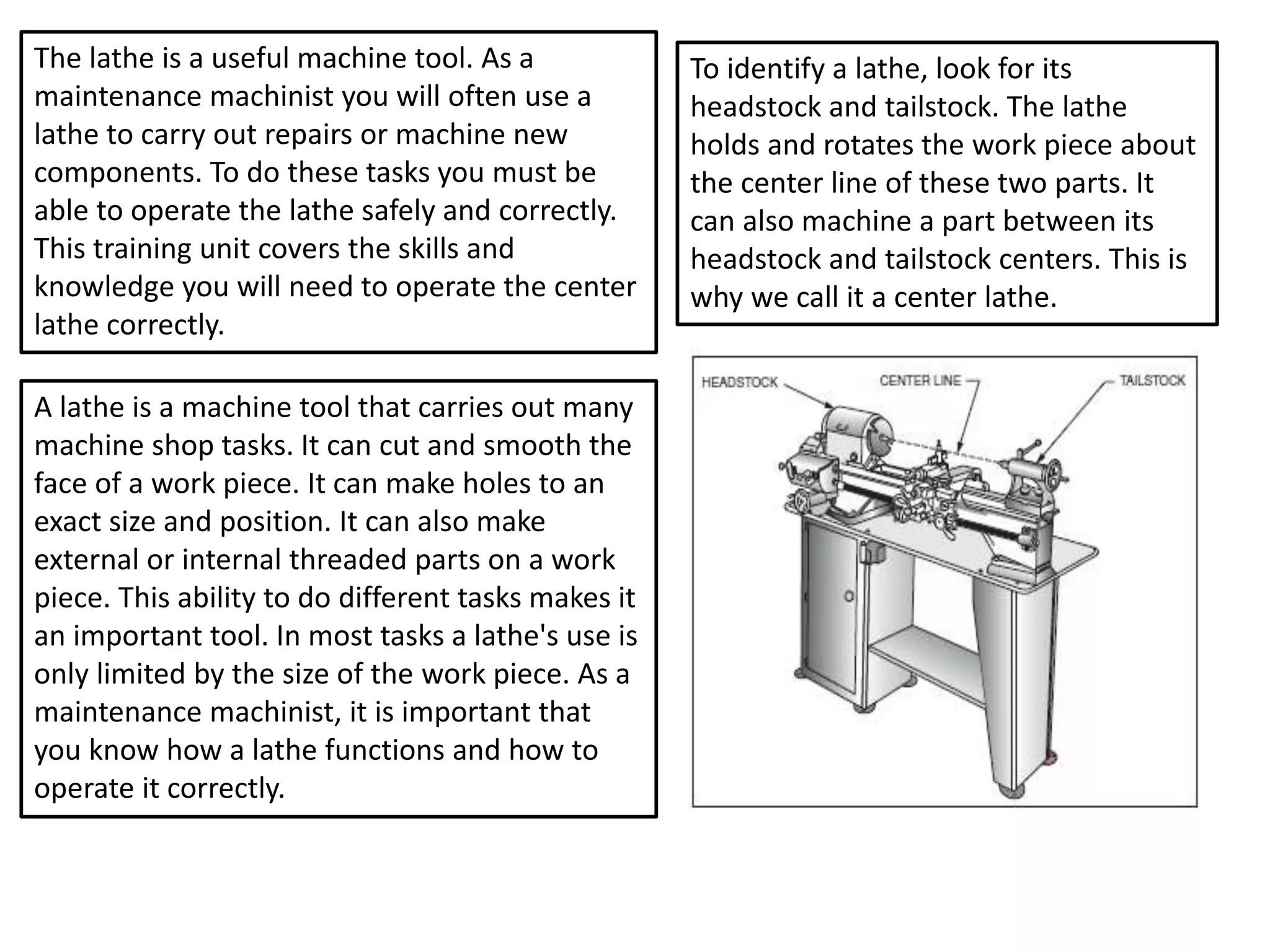
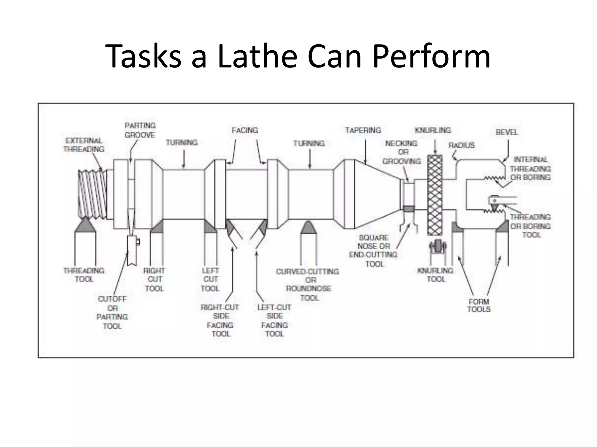
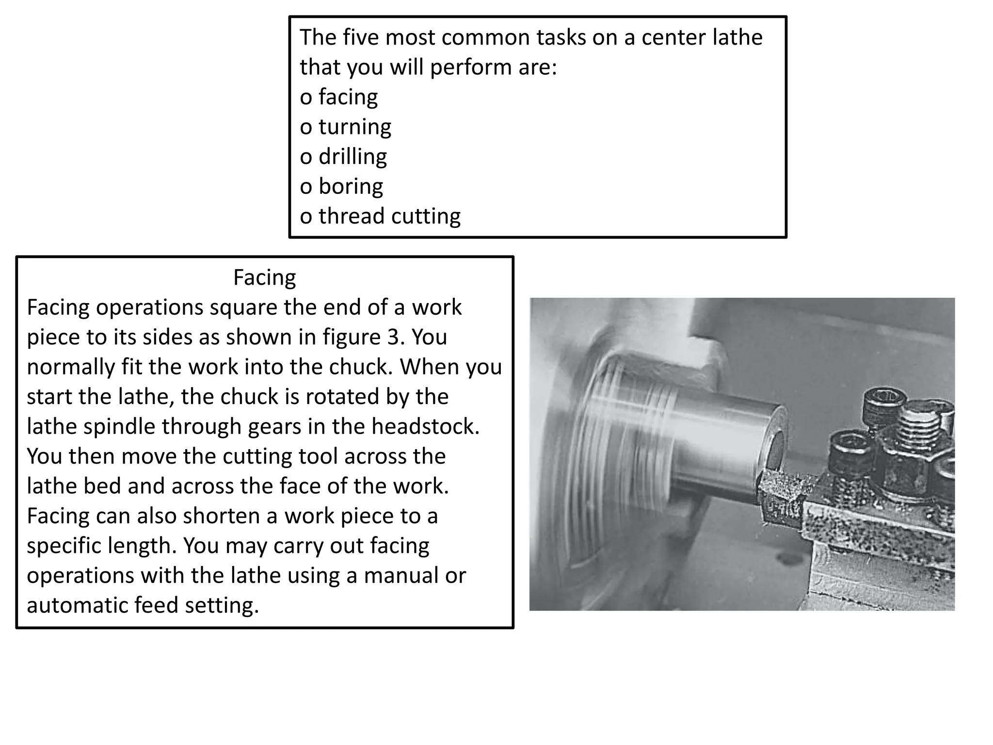

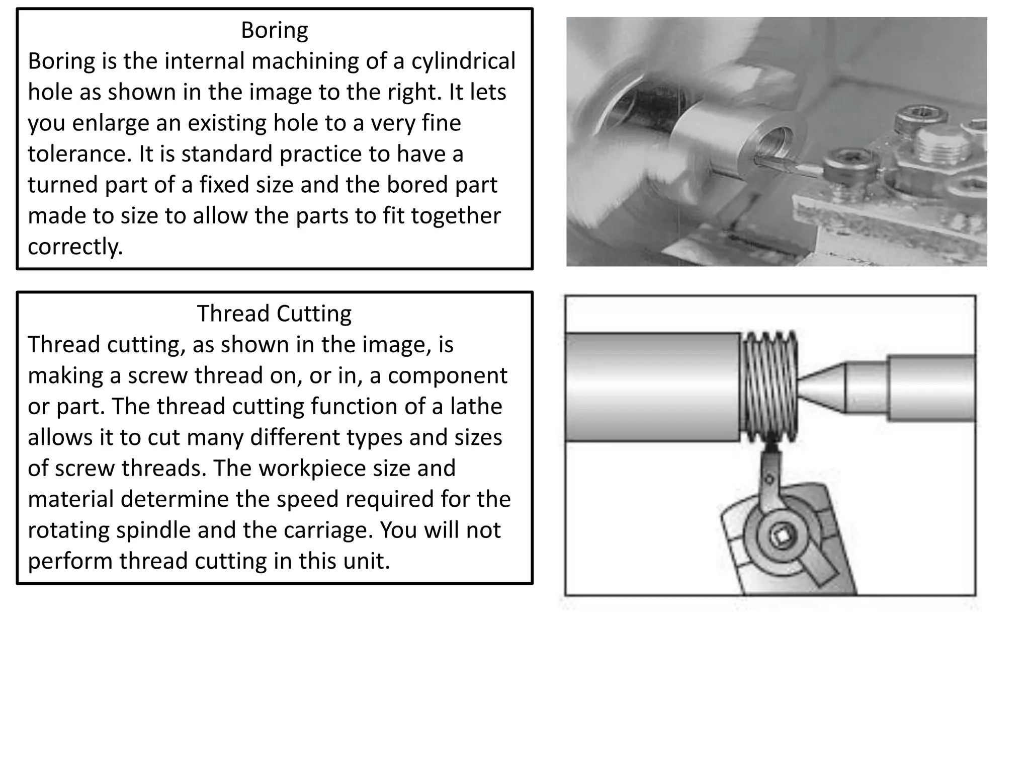


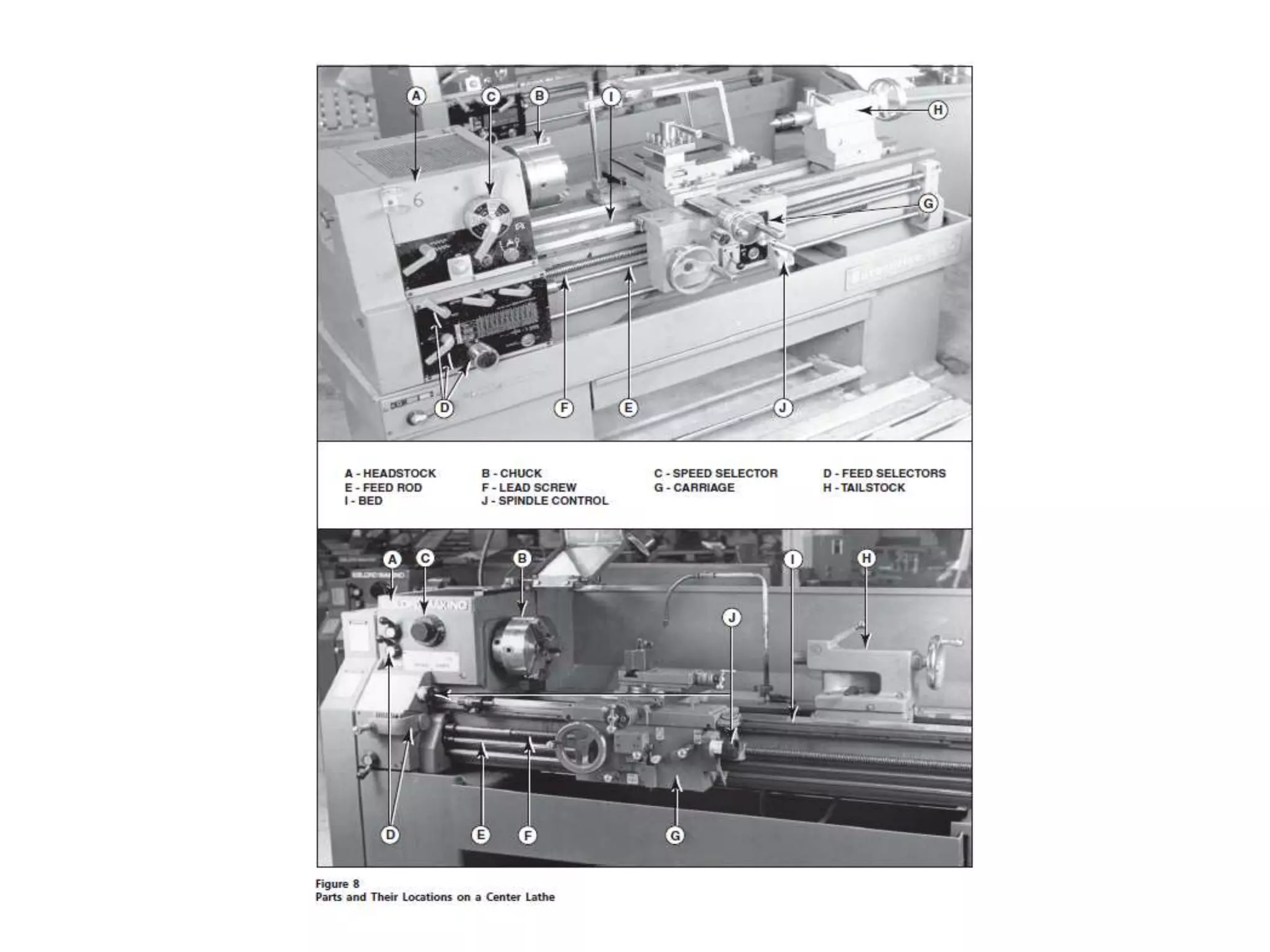
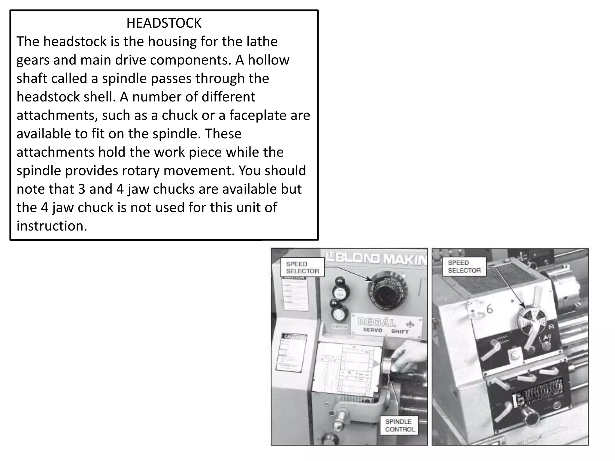
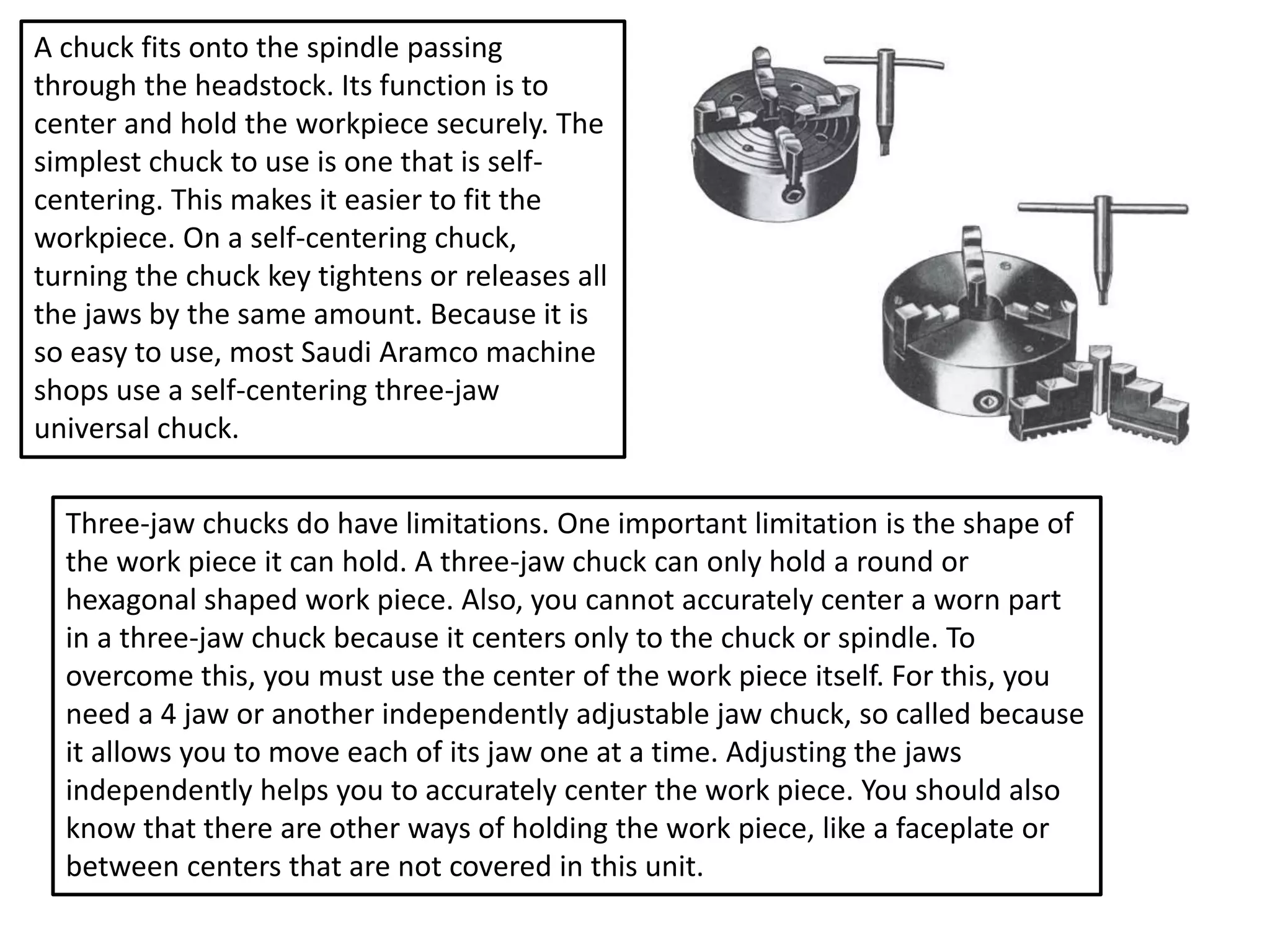


The document provides an overview of the main parts and functions of a center lathe. It details the key components like the headstock, chuck, spindle, carriage, saddle, and tailstock. It explains the main tasks that can be performed on a lathe, including facing, turning, drilling, boring, and thread cutting. The document emphasizes the importance of understanding how to correctly and safely operate a lathe as its fast moving parts and cutting tools can cause serious injuries if mishandled.


