HARDNESS, FRACTURE TOUGHNESS AND STRENGTH OF CERAMICS
Lathe Fundamentals and Operations Guide
1. 8/4/2015
1
Lathe
Lathe
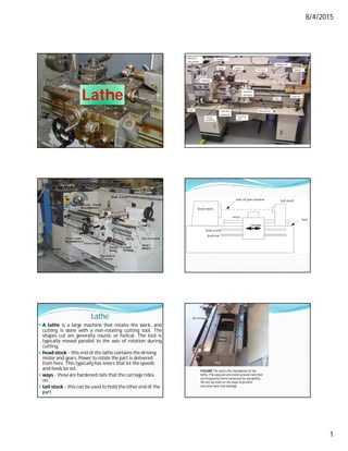
A lathe is a large machine that rotates the work, and
cutting is done with a non-rotating cutting tool. The
shapes cut are generally round, or helical. The tool is
typically moved parallel to the axis of rotation during
cutting.
head stock - this end of the lathe contains the driving
motor and gears. Power to rotate the part is delivered
from here. This typically has levers that let the speeds
and feeds be set.
ways - these are hardened rails that the carriage rides
on.
tail stock - this can be used to hold the other end of the
part.
FIGURE The bed is the foundation of the
lathe. The ways are precision-ground rails that
are frequently flame hardened for durability.
Do not lay tools on the ways to prevent
excessive wear and damage.
2. 8/4/2015
2
FIGURE The carriage supports cutting tools and moves along the
ways to provide tool movement. The top section
that rests on the ways is the saddle and the apron is suspended from
the saddle and hangs down in front of the bed.
Lathe
Bed - this is a bottom pan on the lathe that catches chips,
cutting fluids, etc.
carriage - this part of the lathe carries the cutting tool and
moves based on the rotation of the lead screw or rod.
Lead screw - A large screw with a few threads per inch used
for cutting threads. It has ACME threads with included angle
of 29o for easy engagement and disengagement of half nut.
Lead rod - a rod with a shaft down the side used for driving
normal cutting feeds.
The critical parameters on the lathe are speed of rotation
(speed in RPM) and how far the tool moves across the work
for each rotation (feed in IPR)
Lead Screw and Feed Rod
10
< Lead Screw
< Feed Rod
General classifications used when describing lathes
Swing - the largest diameter of work that can be rotated.
Distance Between Centres - the longest length of
workpiece
Length of Bed - Related to the Distance Between
Centres
Power - The range of speeds and feeds, and the
horsepower available
Number of Spindle Speed
Numberof spindle speed is in a geometric progression.
If n number of spindle speed is required with N1 is the
minimum speed then
The values of step ratios are 1.06, 1.12, 1.26, 1.41, 1.58 and 2
1
1
min
max
max
1
1
min
1
1
1
3
1
2
1
1
1
Ratio
Step
Therefore,
....
,.........
,
,
,
n
n
n
N
N
r
N
r
N
and
N
N
r
N
r
N
r
N
r
N
N
Turning
Turning - produces a smooth and straight outside radius
on a part.
3. 8/4/2015
3
Threading
Threading - The cutting tool is moved quickly cutting
threads.
Threading
In one revolution of the spindle, carriage must travel
the pitch of the screw thread to be cut.
train
gear
carriage
to
spindle
of
ratio
gear
screw
lead
the
of
start
of
Number
cut
be
to
thread
screw
the
of
start
of
Number
screw
lead
the
of
Pitch
L
cut
be
to
thread
screw
the
of
Pitch
L
s
cg
L
s
L
L
s
s
N
N
i
z
z
P
Lz
N
Pz
N
Lead lead is the linear distance the nut travels and the
leadscrew forevery one revolution.
Lead=pitch*starts
Facing
Facing - The end of the part is turned to be square.
Tapering
Tapering - the tool is moves so as to cut a taper (cone
shape).
4. 8/4/2015
4
Drilling/Boring
Drilling/Boring - a cutter or drill bit is pushed into the
end to create an internal feature.
Knurling
Knurling is a manufacturing process whereby a
visually-attractive diamond-shaped (criss-cross)
pattern is cut or rolled into metal.
This pattern allows human hands or fingers to get a
better grip on the knurled object than would be
provided by the originally-smoothmetal surface.
Spinning
Metal Spinning is a process by which circles of metal are
shaped over mandrels (also called forms) while mounted
on a spinning lathe by the application of levered force
with various tools.
Reaming
A reamer enters the workpiece axially through the end
and enlarges an existing hole to the diameter of the
tool. Reaming removes a minimal amount of material
and is often performed after drilling to obtain both a
more accurate diameter and a smoother internal
finish.
Tapping
A tap enters the workpiece axially through the end and
cuts internal threads into an existing hole. The existing
hole is typically drilled by the required tap drill size
that will accommodate the desired tap.
Work holding Devices for Lathes
Held between centers
3 jaw self centering chuck (Disc type jobs being held
in chucks )
4 jaw independently adjusted chuck
Held in a collet (Slender rod like jobs being held in
collets )
Mounted on a face plate (Odd shape jobs, being held
in face plate)
Mounted on the carriage
Mandrels
Magnetic chuck – for thin job
5. 8/4/2015
5
Lathe chucks
Lathe chucks are used to support a wider variety of
workpiece shapes and to permit more operations to be
performed than can be accomplished when the work is
held between centers.
Three-jaw, self-centering chucks are used for work that
has a round or hexagonal cross section.
Each jaw in a four-jaw independent chuck can be moved
inward and outward independent of the others by means
of a chuck wrench. Thus they can be used to support a
wide variety of work shapes.
Combination four-jaw chucks are available in which each
jaw can be moved independently or can be moved
simultaneouslyby means of a spiral cam.
3 Jaw Chuck 4 Jaw Chuck
Collets Magnetic Chuck
Face Plate
Turning
Formula for Turning
Depth of cut,
Averagediameter of workpiece
Cutting Time,
Metal Removal Rate
Cutting Speed, V =
1 2
D D
d DOC mm
2
1 2
avg
D D
D mm
2
L A O
CT
fN
2 2
1 2
av g
D D
M R R D d fN
4 / fN
1
D N
,m / min
1000
IES 2010
In turning a solid round bar, if the travel
of the cutting tool in the direction of
feed motion is 1000 mm, rotational
speed of the workpiece is 500 rpm, and
rate of feed is 0.2 mm/revolution, then
the machining time will be
(a) 10 seconds (b) 100 seconds
(c) 5 minutes (d) 10 minutes
6. 8/4/2015
6
IES - 2003
The time taken to face a workpiece of 72 mm
diameter, if the spindle speed is 80 r.p.m. and cross-
feed is 0.3 mm/rev, is
(a) 1.5 minutes (b) 3.0 minutes
(c) 5.4 minutes(d) 8.5 minutes
Turning Tapers on Lathes
Using a compound slide,
Using form tools,
Offsetting the tailstock, and
Using taper turning attachment.
Using a Compound Slide
Limited movement of the compound slide
Feeding is by hand and is non-uniform. This is
responsible for low-productivity and poor surface
finish.
Can be employed for turning short internal and
external tapers with a large angle of (steep) taper.
Using a Compound Slide contd..
The angle is determined by
l
d
D
2
tan
taper
the
of
length
l
diameter
smaller
d
stock
of
Diameter
D
angle
taper
Half
Offsetting the tailstock
It is necessary to measure the tailstock offset when using
this method.
This method is limited to small tapers (Not exceeding 8o
) over long lengths.
By offsetting the tailstock, the axis of rotation of the job
is inclined by the half angle of taper.
Form tool
Special form tool for generating the tapers is used. The
feed is given by plunging the tool directly into the work.
This method is useful for short external tapers, where
the steepness is of no consequence, such as for
chamfering.
7. 8/4/2015
7
Taper Turning Attachment
Additional equipment is attached at the rear of the lathe.
The cross slide is disconnected from the cross feed nut.
The cross slide is then connected to the attachment.
As the carriage is engaged, and travels along the bed, the
attachment will cause the cutter to move in/out to cut the
taper.
For turning tapers over a comprehensive range is the use
of taper turning attachment.
Errors in tool settings
Setting the tool below the centre decrease actual rake angle,
while clearance angle increases by the same amount. Thus
cutting force increased.
Setting the tool above the centre causes the rake angle to
increase, while clearance angle reduces. More rubbing with
flank.
Turret Lathe
A turret lathe, a number of tools can be set up on the
machine and then quickly be brought successively into
working position so that a complete part can be
machined without the necessity for further adjusting,
changing tools, or making measurements.
Turret Lathe Capstan Lathe
8. 8/4/2015
8
Capstan lathe Turret lathe
Short slide, since the saddle is
clamped on the bed in position.
Saddle moves along the bed, thus
allowing the turret to be of large
size.
Light duty machine, generally for
components whose diameter is less
than 50 mm.
Heavy duty machine, generally
for components with large
diameters, such as 200 mm.
Too much overhang of the turret
when it is nearing cut.
Since the turret slides on the
bed, there is no such difference.
Ram-type turret lathe, the ram and
the turret are moved up to the
cutting position by means of the
capstan Wheel. As the ram is
moved toward the headstock, the
turret is automatically locked into
position.
Saddle-type lathes, the main
turret is mounted directly on the
saddle, and the entire saddle
and turret assembly
reciprocates.
Turret indexing mechanism
The hexagonal turret is rotated (for indexing) by a
Geneva mechanism where a Geneva disc having six radial
slots is driven by a revolving pin. Before starting
rotation, the locking pin is withdrawn by a cam lever
mechanism. The single rotation of the disc holding the
indexing pin is derived from the auxiliary shaft with the
help of another single revolution clutchas indicated.
For automatic lathe: Ratchet and Pawl mechanism
Automatic Lathe
The term automatic is somewhat loosely applied, but is
normally restricted to those machine tools capable of
producing identical pieces without the attention of an
operator, after each piece is completed. Thus, after
setting up and providing an initial supply of material,
further attention beyond replenishing the material
supply is not required until the dimensions of the work
pieces change owing to tool wear.
A number of types of automatic lathes are developed
that can be used for large volume manufacture
application, such as single spindle automatics, Swiss type
automatics,and multi-spindle automatics.
Swiss type AutomaticLathe Or SlidingHeadstockAutomatics
Headstock travels enabling axial feed of the bar stock
against the cutting tools.
There is no tailstock or turret
High spindle speed (2000 – 10,000 rpm) for small job
diameter
The cutting tools (upto five in number including two on
the rocker arm) are fed radially
Used for lot or mass production of thin slender rod or
tubular jobs, like components of small clocks and wrist
watches, by precision machining.
Multi Spindle Automatic Lathe
For increase in rate of production of jobs usually of
smaller size and simpler geometry.
Having four to eight parallel spindles are preferably used.
Multiple spindle automats also may be parallel action or
progressively working type.
9. 8/4/2015
9
Norton type Tumbler-gear quick-change Gear box Norton type Tumbler-gear quick-change Gear box
It comprises a cone of gears 1 to 8 mounted on shaft S2.
The tumbler gear can slide on shaft S1. It can mesh with any
gear on shaft S2 through an intermediate gear which is
located on a swinging and sliding lever so that it can engage
gears 1 to 8 of different diameters, on shaft S2.
The lever can be fixed in any desired ratio position with the
help of a stop pin.
The drive is usually from the driving shaft S1 to the driven
shaft S2.
Drilling
INTRODUCTION
In a drilling machine holes may be drilled quickly and
at low cost. The hole is generated by the rotating edge
of a cutting tool known as the drill which exerts large
force on the work clamped on the table. The cutting
motion is provided by rotating the drill and feeding is
done by giving rectilinear motion to the drill in the
axial direction. Here the drill used has two cutting
edges called lips.
Drilling
Drilling is a operation that cuts cylindrical holes.
TYPES OF DRILL PRESSES
Vertical orpillar type
Radial Arm type
Gang drill
Multi Spindle drill
Numerical Controldrill
10. 8/4/2015
10
Drilling operation
Drilling – Processof making hole
in solid body.
2) Boring – Enlarging a hole
completelywith an adjustabletool
withonly one cutting edge.
3) Counterboring - Enlargingone
end of the hole to form a square
shoulderwithoriginal hole to avoid
projectionsin assemblies.
4) Countersinking - Makinga cone
shapedenlargementto providea
recessfor a screw head.
Drilling Operations
Chip formation
of a drill
Drill
The twist drill does most of the cutting with the tip of
the bit.
•There are flutes
to carry the chips
up from the
cutting edges to
the top of the
hole where they
are cast off.
DRILL TOOL GEOMETRY
11. 8/4/2015
11
Drill Drill
Axial rake angle is the angle between the face and the
line parallel to the drill axis. At the periphery of the drill,
it is equivalent to the helix angle/rake angle.
The lip clearance angle is the angle formed by the
portion of the flank adjacent to the land and a plane at
rightangles to the drill axis measured at the periphery of
the drill. Large angles (80–120) are used for ductile matls.
to compensate elastic recovery. Small angles (60–80) are
used for brittle matls.
Lead of the helix is the distance measured parallel to the
drillaxis, between corresponding pointon the leadingedge
of the land in one complete revolution.
Drill
Drill sizes are typically measured across the drill points with a
micrometer
Most widely used material is High Speed Steel
The drill blanks are made by forging and then are twisted to
provide the torsional rigidity. Then the flutes are machined
and hardened before the final grinding of the geometry.
Deep hole drilling requires special precautions to take care of
the removal of large volume of chips.
Point Angle (2β)
The point angle is selected to suit the hardness and brittleness of
the material being drilled.
Harder materials have higher point angles, soft materials have
lowerpoint angles.
An increase in the drill point angle leads to an increase in the
thrust force and a decrease in the torque due to increase of the
orthogonal rakeangle.
This angle (half) refers to side cutting edge angle(SCEA) of a
singlepoint tool.
Standard PointAngle is 118°
It is 116° to 118° for medium hardsteel and cast iron
It is 125° for hardenedsteel
It is 130° to 140° for brass and bronze
It is only 60° for wood and plastics
Helix Angle (ψ)
Helix angle is the angle between the leading edge of the
land and the axis of the drill. Sometimes it is also called
as spiral angle.
12. 8/4/2015
12
The helix resultsin a positivecutting rake
This angle is equivalent to back rake angle of a single point
cutting tool.
Usual – 20° to 35° – mostcommon
Large helix : 45° to 60° suitable for deep holes and softer
work materials
Small helix : for harder/ stronger materials
Zero helix : spade drills for high production drilling micro-
drillingand hard work materials
GATE- 1997
Helix angle of fast helix drill is normally
(a) 35o
(b) 60o
(c) 90o
(d) 5o
Cutting Speed in Drilling
The cutting speed in drilling is the surface speed of the
twistdrill.
/ min
1000
DN
V m
Drilling Time
Time for drilling the hole
Example
A hole with 40-mm diameter and 50-mm depth is to
be drilled in mild steel component. The cutting
speed can be taken as 65 m/min and the feed rate as
0.25 mm/rev. Calculate the machining time and the
material removal rate.
Some Formulae for Drilling
1
( )
2tan
( ) sin
2
( )
2sin
2 / tan
( ) tan
sin
D
Coneheight h
f
Uncut chipthickness t
D
Widthof cut b
r D
Orthogonal rakeangle
13. 8/4/2015
13
GATE- 2002
The time taken to drill a hole through a 25 mm thick
plate with the drill rotating at 300 r.p.m. and
moving at a feed rate of 0.25 mm/revolutionis
(a) 10 sec (b) 20 sec
(c) 60 sec (d) 100 sec
GATE- 2004
Through holes of 10 mm diameter are to be drilled
in a steel plate of 20 mm thickness. Drill spindle
speed is 300 rpm, feed 0.2 mm/ rev and drill point
angle is 120°. Assuming drill over travel of 2 mm, the
time forproducing a hole will be
(a) 4 seconds (b) 25 seconds
(c) 100 seconds (d) 110 seconds
GATE – 2007 (PI) Linked S-1
Blind holes 10 mm diameter, 50 mm deep are
being drilled in steel block. Drilling spindle
speed is 600 rpm, feed 0.2 mm/rev, point angle of
drill is 120o.
Machining time (in minutes) per hole will be
(a) 0.08 (b) 0.31 (c) 0.44 (d) 0.86
GATE – 2007 (PI) Linked S-2
Blind holes 10 mm diameter, 50 mm deep are
being drilled in steel block. Drilling spindle
speed is 600 rpm, feed 0.2 mm/rev, point angle of
drill is 120o.
During the above operation, the drill wears out
after producing 200 holes. Taylor’s tool life
equation is of the form VT0.3 = C, where V =
cutting speed in m/minute and T = tool life in
minutes. Taylor’s constant C will be
(a) 15 (b) 72 (c) 93 (d) 490
Reaming, Boring, Broaching
14. 8/4/2015
14
Reaming
Reaming
Reaming removes a small amount of material from the
surface of holes.
It is done for two purposes: to bring holes to a more exact
size and to improve the finish of an existing hole.
Multiage cutting tools that has many flutes, which may be
straight or in a helix are used.
No special machines are built for reaming. The same
machine that was employed for drilling the hole can be used
for reaming by changing the cutting tool.
Only a minimum amount of materials should be left for
removal by reaming. As little as 0.1 mm is desirable, and in
no case should the amount exceed 0.4 mm.
A properly reamed hole will be within 0.025 mm of the
correct size and have a fine finish.
Reamer
Reamer Flutes
The reamer flutes are either straight or helical.
The helical flutes promote smoother cutting and should be
used specifically for holes that are not continuous, such as
those with keyways parallel to the axis of the hole.
The cutting action of the helical flutes is smoother and helps
in preventing chatter.
The reamers are termed as left hand or right hand,
depending upon the direction in which they are moved,
looking from the shank to the cutting portion.
a) Straight flute reamer is used for through holes in materials
that do not form chips like C.I, Bronze, Brass. They form fine
powder that will fall by gravity.
b) Left hand spiral flute reamer is used for through holes in
other materials and is very effective as they push the chips
out of the through hole.
c) Right hand spiral flute reamer is used for blind holes as
they pull the chips out of them
15. 8/4/2015
15
Types of Reamers
The principal types of reamers are:
1. Hand reamers
a. Straight
b. Taper
2. Machineor chucking reamers
a. Rose
b. Fluted
3. Shell reamers
4. Expansion reamers
5. Adjustablereamers
Reaming
To meet quality requirements, including both finish and
accuracy (tolerances on diameter, roundness,
straightness, and absence of bell-mouth at ends of
holes). Reamers must have adequate support for the
cutting edges, and reamer deflection must be minimal.
Reaming speed is usually two-thirds the speed for
drilling the same materials. However, for close tolerances
and fine finish, speeds should be slower.
Feeds are usually much higher than those for drilling
and depend upon material.
Recommended cutting fluids are the same as those for
drilling.
Reaming
Reamers, like drills, should not be allowed to become dull.
The chamfer must be reground long before it exhibits
excessive wear. Sharpening is usually restricted to the
starting taper or chamfer. Each flute must be ground exactly
evenly or the tool will cut oversize.
Reamers tend to chatter when not held securely, when the
work or work holder is loose, or when the reamer is not
properly ground.
Irregularly spaced teeth may help reduce chatter. Other cures
for chatter in reaming are to reduce the speed, vary the feed
rate, chamfer the hole opening, use a piloted reamer, reduce
the relief angle on the chamfer, or change the cutting fluid.
Any misalignment between the work piece and the reamer
will cause chatter and improper reaming.
Rose Reamer
Rose reamers are primarily used for roughing prior to final
reaming. The cylindrical part of the reamer has no
cutting edges, but merely grooves cut for the full length of
the reamer body, providing a way for the chips to escape
and a channel for lubricant to reach the cutting edges. To
prevent binding they have a slight back taper. The cutting
edges at the end are ground to a 450 bevel.
Chucking Reamer
Fluted chucking
reamers have relief
behind the edges of the
teeth as well as beveled
ends. They can cut on
all portions of the teeth.
Their flutes are
relatively short and they
are intended for light
finishing cuts.
Shell Reamer
Shell reamers are similar to
cutting portion of a
chucking reamer. They are
supplied without a shank
and has a hole through the
center. A arbor is used in
conjunctionwith the shell
reamer, the slots in the
reamer engage lugs on the
arbor for driving power
16. 8/4/2015
16
Trepanning
Trepanning – Operation of producing a hole by
removing metal along the circumference of a hollow
cutting tool. Used for producing large holes in plates.
Trepanning Tool
VIDEO 2,3 &4
Boring
Boring
Boring always involves the enlarging of an existing hole,
which may have been made by a drill or may be the result of a
core in a casting.
An equally important and concurrent purpose of boring may
be to make the hole concentric with the axis of rotation of
the workpiece and thus correct any eccentricity that may
have resulted from the drill drifting off the centerline.
Concentricity is an important attribute of bored holes.
When boring is done in a lathe, the work usually is held in a
chuck or on a faceplate. Holes may be bored straight,
tapered, or to irregular contours.
Boring is essentially internal turning while feeding the tool
parallel to the rotation axis of the workpiece.
Tungsten carbidetool tip
17. 8/4/2015
17
Boring
The same principles are used for boring as for turning.
The tool should be set exactly at the same height as the
axis of rotation. Slightly larger end clearance angles
sometimes have to be used to prevent the heel of the tool
from rubbing on the inner surface of the hole.
Boring
Because the tool overhang will be greater, feeds and
depths of cut may be somewhat less than for turning to
prevent tool vibration and chatter.
In some cases, the boring bar may be made of tungsten
carbide because of this material's greater stiffness.
The boring tool is a single-point cutting tool.
Hole quality, finish boring can typically achieve holes
within tolerances of IT9.
Surface finishes better than Ra 1 micron can be achieved.
Formula for Boring
Averagediameter of workpiece
Cutting Time,
Metal Removal Rate
1 2
avg
D D
D mm
2
L A O
CT
fN
2 2
1 2
av g
D D
M R R D d fN
4 / fN
Broaching
Broaching
Broaching is a multiple-tooth cutting operation with the
tool reciprocating.
Since in broaching the machining operation is
completed in a single-stroke as the teeth on the cutting
tool, called broach, are at gradually increasing height
corresponding to the feed per tooth of a milling cutter.
The shape of the broach determines the shape of the
machined part.
Broaching was originally developed for machining
internal keyways, but looking at the advantages, it has
been extensively used in the mass production of
automobile component manufacture for various other
surfacesas well.
18. 8/4/2015
18
Broaching
The material removal using the broach teeth is shown
schematically in Fig. shown in below. The dotted line in
the figure indicates the amount of material being
removed by successive individual teeth.
Broach Construction
Broach Construction
The broach is composed of a series of teeth, each tooth
standing slightly higher than the previous one. This rise
per tooth is the feed per tooth and determines the
material removed by the tooth.
There are basically three sets of teeth present in a broach
as shown in Fig. shown above.
The roughing teeth that have the highest rise per tooth
remove bulk of the material.
The semi-finishing teeth, whose rise per tooth is smaller,
remove relatively smaller amounts of material compared
to the roughing teeth.
Broach Construction
The last set of teeth is called the finishing or sizing teeth.
Very little material will be removed by these teeth.
The necessary size will be achieved by these teeth and
hence all the teeth will be of the same size as that
required finally. With the progress of time, when the
first set of teeth wear out, the next set of teeth will be
able to provide the sizing function.
The pull end of the broach (Fig. shown in above) is
attached to the pulling mechanism of the broaching
machine with the front pilot aligning the broach properly
with respect to the workpiece axis before the actual
cutting starts.
Broach Construction
The rear pilot helps to keep the broach to remain square
with the workpiece as it leaves the workpiece after
broaching.
Broaching speeds are relatively low, of the order of 6 to 15
m/min. However, the production rate is high with the
cycle times being about 5 to 30 seconds, including the
workpiece and tool handling times. The low cutting
speeds are conducive to very high tool life with very
small tool wear rates.
Broach Construction
Broaches are generally made of high speed steel in view
of its high impact strength. Sometimes, the titanium
nitride coating helps to improve the tool life further.
Also, the carbide insert-type broaches are used more for
surface broaching of cast iron for very large volume
production to reduce the frequent re-sharpening of the
broach, which is a very difficult operation.
Standard broaches are available for common and more
often used forms, such as round and square holes,
keyways, etc.
19. 8/4/2015
19
Broach Construction
For smooth operation, it is essential that at least two or
three teeth be simultaneouslyengaged.
The thumb rule for tooth spacing,
In the normal speed BUE may be a problem. To avoid
this a copious supply of the cutting fluid is provided.
1.75 ,
s l mm
Advantages of broaching
1. It is the fastest way of finishing an operation with a single
stroke.
2. Since all the machining parameters are built into the
broach, very little skill is required from the operator.
3. Broaching machine is simple since only a single
reciprocating motion is required for cutting.
4. Final cost of the machining operation is one of the lowest
for mass production.
5. Any type of surface, internal or external, can be generated
with broaching.
6. Many surfaces, which are very difficult or impossible by
other means, can be done by broaching. For example, square
hole and internal splines.
7. Good surface finish and fine dimensional tolerances can be
achieved by broaching, often better than boring or reaming
Limitations of broaching
1. Custom made broaches are very expensive and can
therefore be justified only for very large volume
production.
2. A broach has to be designed for a specific application
and can be used only for that application. Hence, the
lead time for manufacture is more for custom designed
broaches.
3. Broaching, being a very heavy metal removal
operation, requires that the workpiece is rigid and
capable of withstanding the large forces.
4. Broaching can only be carried out on the workpiece
whose geometry is such that there is no interference for
the broach movement for the cutting.
Milling
Milling
2-D contouring like cam profiles, clutches etc and 3-D
contouring like die or mould cavities
Cutting teeth in piece or batch production of spur gears,
straight toothed bevel gears, worm wheels, sprockets,
clutchesetc.
Producing some salient features like grooves, flutes,
gushing and profiles in various cutting tools, e.g., drills,
taps, reamers, hobs, gear shaping cuttersetc.
Accuracy is very poor so grinding must be done after
milling
Up milling and down milling
20. 8/4/2015
20
Up milling and down milling
In down milling, though the cut starts with a full chip
thickness, the cut gradually reduces to zero. This helps in
eliminating the feed marks present in the case of up
milling and consequently better surface finish.
Climb milling also allows greater feeds per tooth and
longer cutting life between regrinds than the
conventional milling.
Up milling needs stronger holding of the job and down
milling needs backlash free screw-nut systems for
feeding.
fz =0.1mm
Numberof teeth=10
Feed=1mm/rev
Speed=Feed*N
Advantages of Down Milling
1. Suited to machine thin and hard-to-hold parts since
the workpiece is forced against the table or holding
device by the cutter.
2. Work need not be clamped as tightly.
3. Consistent parallelism and size may be maintained,
particularlyon thin parts.
4. It may be used where breakout at the edge of the
workpiece could not be tolerated.
5. It requires upto 20% less power to cut by this method.
6. It may be used when cutting off stock or when milling
deep, thin slots.
Disadvantages of Down Milling
1. It cannot be used unless the machine has a backlash
eliminator and the table jibs have been tightened.
2. It cannot be used for machining castings or hot rolled
steel, since the hard outer scale will damage the cutter.
Slab or Plain milling cutters
Plain Milling : Producing plain, flat horizontal surface. This
is called slab milling if performed with a peripheral cutter
and called face Milling if a face milling cutter is used
21. 8/4/2015
21
Side and slot milling cutters Slitting saw or parting tool
End milling cutters or End mills Face milling cutters
Use of form relieved cutters (milling)
Tool form cutters
22. 8/4/2015
22
T- slot cutter Gear teeth milling cutters
Spline shaft cutters Straddle milling
ViDEO 11
Gang milling Turning by rotary tools (milling cutters)
23. 8/4/2015
23
Milling Velocity
The cutting speed in milling is the surface speed of the
milling cutter.
DN
V
1000
Milling Time
Time for one pass = minutes
Approach distance,
L 2 A
fZN
2 2
D D
A d d D d
2 2
For face milling
24. 8/4/2015
24
MRR in Milling
Considering the parameters defined in the discussionof
speeds and feeds, etc, the MRR is given below,
Where,
MRR =
where, w = width of cut, d = depth of cut
w d F
Some Formulae for Milling
max
a
2
max 2 2
2
Maximum uncut chip thickness (t )
Average uncut chip thickness(t )
Peak to valley surface roughness (h )
4
vg
f d
NZ D
f d
NZ D
f
DN Z
GATE - 1993
A milling cutter having 8 teeth is rotating at 150
rpm. If the feed per tooth is 0.1 mm, the table speed
in mm per minute is
(a) 120 (b) 187
(c) 125 (d) 70
GATE - 1992
In horizontal milling process…………. (up/down)
milling provides better surface finish and…………..
(up-down) milling provides longertool life.
Shaper, Planner, Slotter
25. 8/4/2015
25
Shaper
The relative motions between the tool and the workpiece,
shaping and planing use a straight-line cutting motion with a
single-point cutting tool to generate a flat surface.
In shaping, the workpiece is fed at right angles to the cutting
motion between successive strokes of the tool.
For either shaping or planing, the tool is held in a clapper box
which prevents the cutting edge from being damaged on the
returnstroke of the tool.
Relatively skilled workers are required to operate shapers and
planers, and most of the shapes that can be produced on
them also can be made by much more productive processes,
such as milling, broaching, or grinding.
Shaper
Quick return motion Mechanism Formula
Cutting speed,
Numberof strokes,
Time of one stroke,
Total time,
(1 )
1000
NL m
V
s
w
N
f
(1 )
min
1000
L m
t
V
(1 ) (1 )
min
1000 1000
s
L m Lw m
T N
v vf
Hydraulic Shaper
26. 8/4/2015
26
Slotter
GATE - 2005
A 600 mm x 30 mm flat surface of a plate is to be
finish machined on a shaper. The plate has been
fixed with the 600 mm side along the tool travel
direction. If the tool over-travel at each end of the
plate is 20 mm, average cutting speed is 8 m/min,
feed rate is 0.3 mm/stroke and the ratio of return
time to cutting time of the tool is 1:2, the time
required formachining will be
(a) 8 minutes (b) 12 minutes
(c) 16 minutes (d) 20 minutes
Grinding & Finishing
Process Features
Grinding Useswheels,accurate sizing, finishing, low MRR;
can be done at high speeds .
Creep feed
grinding
Useswheelswith long cutting arc, very slow feed
rateand largedepth of cut
Abrasive
machining
High MRR, to obtain desiredshapesand
approximatesizes
Abrasivewater
jet Machining
Waterjets with velocitiesup to 1000 m/sec carry
abrasiveparticles (silica and garnet)
Honing "Stones"containing fineabrasives; primarilya
hole - finishing process
Lapping Fineparticlesembedded in soft metal or cloth;
primarilya surface-finishingprocess
Abrasive Machining Processes
27. 8/4/2015
27
Grinding
Grinding is the most common form of abrasive
machining.
It is a material cutting process which engages an abrasive
tool whose cutting elements are grains of abrasive
material known as grit.
These grits are characterized by sharp cutting points,
high hot hardness, and chemical stability and wear
resistance.
The grits are held together by a suitable bonding
material to give shape of an abrasive tool.
Grinding can be compared with milling with an infinite
numberof cutting edge.
Fig- cutting action of abrasive grains
Why is high velocity desired in grinding?
It is desired to off set the adverse effect of very high
negative rake angle of the working grit, to reduce the
force per grit as well as the overall grinding force.
Advantages of Grinding
Dimensional accuracy
Goodsurface finish
Good form and locational accuracy
Applicable to both hardened and unhardened material
Applications of Grinding
Surface finishing
Slitting and parting
Descaling, deburring
Stock removal (abrasive milling)
Finishing of flat as well as cylindrical surface
Grinding of tools and cutters and resharpening of the
same
Grinding
If each abrasive grain is viewed as a cutting tool then in
grinding operation.
High
Rake angle can be positive, zero, or negative ranging from
+45o to -60o, dull, rounded grits has large negative rake angle
Cutting speed is very high
Very high specific energy of cutting
Low
Low shear angle
Low feed rate
Low depth of cut
28. 8/4/2015
28
Interaction of the grit with the workpiece
Grit with favourable geometry can produce chip in shear
mode.
However, grits having large negative rake angle or
rounded cutting edge do not form chips but may rub or
make a groove by ploughing leading to lateral flow of the
workpiece material.
Fig- Grits engage shearing, ploughing and rubbing
How is chip accommodation volume is
related to material removal rate?
Volume of chip accommodation space ahead of each grit
must be greater than the chip volume produced by each
grit to facilitate easy evacuation of the chip from the
grinding wheel.
Specific energy consumption in grinding
Velocity
low
ploughing
and
rubbing
increases
G Ratio
The grinding ratio or G ratio is defined as thee cubic mm of
stock removed divided by the cubic mm of wheel lost.
In conventional grinding, the G ratio is in the range 20: 1 to
80: 1.
The G ratio is a measure of grinding production and reflects
the amount of work a wheel can do during its useful life.
As the wheel losses material, it must be reset or repositioned
to maintain workpiece size.
Parameters for specify a grinding wheel
1) The type of grit material
2) The grit size
3) The bond strength of the wheel, commonly known
as wheel hardness
4) The structure of the wheel denoting the porosity i.e.
the amount of inter grit spacing
5) The type of bond material
6) Other than these parameters, the wheel
manufacturer may add their own identification code
prefixing or suffixing (or both) the standard code.
Essential parameter
29. 8/4/2015
29
Abrasive
Material
Comments and Uses
Aluminium oxide Softer and tougher than silicon
carbide; use on steel, iron, brass
Silicon carbide Used for brass, bronze,
aluminum, stainless steel and
cast iron
cBN (cubic boron
nitride)
For grinding hard, tough tool
steels, stainless steel, cobalt and
nickel based superalloys, and
hard coatings
Diamond Used to grind nonferrous
materials, tungsten carbide and
ceramics
Why is aluminium oxide preferred to
silicon carbide in grinding steel?
Al2O3 is tougher than SiC. Therefore it is
preferred to grind material having high tensile
strength like steel. Moreover, Al2O3 shows higher
chemical inertness than SiC towards steel leading
to much improved wear resistance during
grinding.
Grit size
The grain size affects material removal rate and the
surfacequality of workpiece in grinding.
Large grit- big grinding capacity, rough workpiece
surface
Fine grit- small grinding capacity, smooth workpiece
surface
Grade
The worn out grit must pull out from the bond and make
room for fresh sharp grit in order to avoid excessive rise
of grinding force and temperature.
A soft wheel should be chosen for grinding hard
material.
A hard wheel should be chosen for grinding soft
material.
Structure / concentration
The structure should be open for grinding wheels
engaged in high material removal to provide chip
accommodation space.
The space between the grits also serves as pocket for
holding grinding fluid.
Dense structured wheels are used for longer wheel life,
for holding precision forms and profiles.
Why is coarse grain and open structured wheel
is preferredfor stock removal grinding?
Coarse grit allows large grit protrusion and open
structure provides large inter grit chip space. Thus in
combination those two provide large space for chip
accommodation during stock removal grinding and risk
of wheel loading is minimized.
Bulge, Swell, Belly
30. 8/4/2015
30
Bonding Materials for Grinding wheels
Type of Bond Attributes
Vitrified bonds Composed of clays and other ceramic
substances, porous, strong, rigid, and
unaffected by oils, water, or
temperature. Brittle and can not be used
for high wheel speed.
Resinoid, or
phenolic
resins
Plastic bond, replaced shellac and
rubber wheels, not with alkaline
grinding fluid.
Shellac bond For flexible cut off wheels, replaced by
resin bond.
Bonding Materials for Grinding wheels
Type of Bond Attributes
Rubber bond For use in thin wheels, replaced by resin
bond.
Oxychloride
bond
Limited use.
Metal bond Extensively used with super abrasive
wheels, high toughness, high accuracy,
large stock removal.
Electroplated
bond
Used for small wheel, form wheel and
thin super abrasive wheels, for abrasive
milling and ultra high speed grinding.
Replace by electroplated bond
Glazing
With continuous use a grinding wheel becomes dull with
the sharp abrasive grains becoming rounded.
This condition of a dull grinding wheel with worn out
grains is termed as glazing.
Loading/Clogging
Some grinding chips get lodged into the spaces between
the grits resulting in a condition known as loaded wheel.
Loading is generally caused during the grinding of soft
and ductile materials.
A loaded grinding wheel cannot cut properly and need
dressing.
Dressing
Dressing is the conditioning of the wheel surface which
ensures that grit cutting edges are exposed from the
bond and thus able to penetrate into the workpiece
material.
In dressing attempts are made to splinter the abrasive
grains to make them sharp and free cutting and also to
remove any residue left by material being ground.
Dressing therefore produces micro-geometry.
Video-9 Truing
Truing is the act of regenerating the required geometry
on the grinding wheel.
Truing is also required on a new conventional wheel to
ensureconcentricity with specific mounting system.
Truing and dressing are commonly combined into one
operation for conventional abrasive grinding wheels, but
are usually two distinctly separate operation for super
abrasive wheel.
31. 8/4/2015
31
Balancing Grinding Wheels
Because of the high rotation speeds involved, grinding
wheels must never be used unless they are in good
balance.
Grinding wheel must be balanced Statically and
Dynamically.
A slight imbalance will produce vibrations that will cause
waviness in the work surface. It may cause a wheel to
break, with the probability of serious damage and injury.
Creep feed grinding
This machine enables single pass grinding of a surface
with a larger down feed but slower table speed than that
adopted for multi-pass conventional surface grinding.
In creep-feed grinding, the entire depth of cut is
completed in one pass only using very small in-feed
rates.
State the basic advantage of a creep feed
grinder over a conventional surface
Productivity is enhanced and life of the grinding wheel is
extended.
Depth of cut is more BUT Feed is low
Cylindrical Grinding
Center-type cylindrical grinding is commonly used far
producing external cylindrical surfaces.
The grinding wheel revolves at an ordinary cutting
speed, and the workpiece rotates on centers at a much
slower speed.
Grinding machines are available in which the workpiece
is held in a chuck for grinding both external and internal
cylindrical surfaces.
Video-5
Centerless Grinding
Centerless grinding makes it possible to grind both
external and internal cylindrical surfaces without
requiring the workpiece to be mounted between centers
or in a chuck.
This eliminates the requirement of center holes in some
workpieces and the necessity for mounting the
workpiece, thereby reducing the cycle time.
Two wheels are used. The larger one operates at regular
grinding speeds and does the actual grinding. The
smaller wheel is the regulating wheel. It is mounted at
an angle to the plane of the grinding wheel.
Video-7a
32. 8/4/2015
32
Centerless Grinding
The regulating wheel controls the rotation and
longitudinal motion of the workpiece and usually is a
plastic- or rubber-bonded wheel with a fairly wide face.
The workpiece is held against the work-rest blade by the
cutting forces exerted by the grinding wheel and rotates
at approximately the same surface speed as that of the
regulating wheel.
Centerless Grinding
Centerless Grinding
The axial feed is calculated by the equation
F = dN sin
where
F = feed (mm/min)
d = diameter of the regulating wheel (mm)
N = revolutions per minute of the regulating wheel
= angle of inclination of the
regulating wheel
Centreless internal Grinding
This machine is used for grinding cylindrical and
tapered holes in cylindrical parts (e.g. cylindrical liners,
various bushings etc).
The workpiece is rotated between supporting roll,
pressure roll and regulating wheel and is ground by the
grinding wheel.
State the disadvantages of centreless
cylindrical grinding machine?
• It does not grind concentricallywith centres.
• Large diameter short workpiece are difficult to
control in the process
• It may not improve workpiece perpendicularity.
Surface Grinding Machines
Surface grinding machines are used primarily to
grind flat surfaces.
However formed, irregular surfaces can be
produced on some types of surface grinders by use
of a formed wheel.
Four basic types of surface grinding machines are:
1. Horizontal spindle and reciprocating table
2. Vertical spindle and reciprocating table
3. Horizontal spindle and rotary table
4. Vertical spindle and rotary table
33. 8/4/2015
33
Lapping
Lapping is basically an abrasive process in which loose
abrasives function as cutting points finding momentary
supportfrom the laps.
Material removal in lapping usually ranges from .003 to
.03 mm but many reach 0.08 to 0.1mm in certain cases.
Video-2a,2 & 3 Characteristics of lapping process
Use of loose abrasive between lap and the workpiece
Usually lap and workpiece are not positively driven but
are guided in contact with each other
Relative motion between the lap and the work should
change continuouslyso that path of the abrasive grains
of the lap is not repeated on the workpiece.
Cast iron is the mostly used lap material. However, soft
steel, copper, brass, hardwood as well as hardened steel
and glass are also used.
Abrasives of lapping
Al2O3 and SiC, grain size 5 ~100 μm
Cr2O3, grain size 1 ~ 2 μm
B4C3, grain size 5 - 60 μm
Diamond, grain size 0.5 ~ 5 μm
Vehicle materials for lapping
Machineoil
Rapeside oil
grease
34. 8/4/2015
34
Technical parameters affecting lapping processes are
unitpressure
the grain size of abrasive
concentration of abrasive in the vehicle
lapping speed
Honing
Honing is a finishing process, in which a tool called
hone carries out a combined rotary and reciprocating
motion while the workpiece does not perform any
working motion.
Most honing is done on internal cylindrical surface, such
as automobile cylindrical walls. The honing stones are
held against the workpiece with controlled light
pressure. The honing head is not guided externally but,
instead, floats in the hole, being guided by the work
surface.
Video-1
Honing
It is desired that
1. Honing stones should not leave the work surface
2. Stroke length must cover the entire work length.
3. In honing rotary and oscillatory motions are
combined to produce a cross hatched lay pattern.
The honing stones are given a complex motion so as
to prevent every single grit from repeating its path
over the work surface.
Fig. Honing tool Fig.Lay pattern produced bycombinationof rotaryand
oscillatorymotion
Honing
The critical process parameters are
1. rotation speed
2. oscillation speed
3. length and position of the stroke
4. honing stick pressure
35. 8/4/2015
35
Burnishing
It consists of pressing hardened steel balls or rolls on
to the surface of W.P. and also imparting feed motion
to the same so that it causes plastic flow of minute
irregularities like dents, projections etc.
Shaft
burnished
on lathe
Video-4
Polishing & Buffing
Polishing is a finishing operation to improve the
surface finish by means of a polishing wheel made of
fabrics or leather and rotating at high speed.
The abrasive grains are glued to the outside periphery
of the polishing wheel.
Polishing operations are often accomplished manually.
Polishing is used to remove scratches and burrs and to
smooth rough surfaces.
Video-5 & 6
Buffing is a finishing operation similar to polishing, in
whichabrasive grains are not glued to the wheel but are
contained in a buffing compound that is pressed into the
outside surface of the buffing wheel while it rotates. As
in polishing, the abrasive particles must be periodically
replenished. Buffing is usually done manually.
Machinesare also available to do buffing automatically.
Negligible amount of material is removed in buffing
while a very high luster is generated on the buffed
surface.
The dimensional accuracy of the parts is not affected by
the buffing operation.
Super Finishing
Fig. super finishing of end face
of a cylindricalwork piece in radial mode
In this both feeding and oscillation of the super
finishing stone is given in the radial direction.
Fig. super finishing operation in plunge mode
Super Finishing
In this case the abrasive stone covers the section of the
workpiece requiring super finish. The abrasive stone is
slowly fed in radial direction while its oscillation is
imparted in the axial direction. It reduce surface
roughness and increase bearing load capacity.
State the specific application of a planetary
internal grinder.
Planetary internal grinders find application for grinding
holes in workpieces of irregular shape or large heavy
workpieces.
36. 8/4/2015
36
Metal Casting
Sand casting
Sand casting uses ordinary sand as the primary
mould material.
The sand grains are mixed with small amounts of
other materials, such as clay and water, to improve
mouldability and cohesive strength, and are then
packed around a pattern that has the shape of the
desired casting.
The pattern must be removed before pouring, the
mold is usually made in two or more pieces.
An opening called a sprue hole is cut from the top of
the mold through the sand and connected to a
system of channels called runners. Contd….
The molten metal is poured into the sprue hole, flows
through the runners, and enters the mold cavity
through an opening called a gate.
Gravity flow is the most common means of
introducing the metal into the mold.
After solidification, the mold is broken and the
finished casting is removed.
The casting is then “fettled” by cutting off the ingate
and the feeder head.
Because the mold is destroyed, a new mold must be
made for each casting.
Contd…
Sequential steps in making a sand casting
A pattern board is placed between the bottom (drag)
and top (cope) halves of a flask, with the bottom side up.
Sand is then packed into the drag half of the mold.
A bottom board is positioned on top of the packed sand,
and the mold is turned over, showing the top (cope) half
of pattern with sprueand riser pins in place.
The cope half of the mold is then packed with sand.
Contd…
The mold is opened, the pattern board is drawn
(removed), and the runner and gate are cut into the
surfaceof the sand.
The mold is reassembled with the pattern board
removed, and molten metal is poured through the
sprue.
The contents are shaken from the flask and the metal
segment is separated from the sand, ready for further
processing.
37. 8/4/2015
37
Casting Terms
Flask: A moulding flask is one which holds the sand
mould intact. It is made up of wood for temporary
applications or metal for long-term use.
Drag: Lower moulding flask.
Cope: Upper moulding flask.
Cheek: Intermediate moulding flask used in three-
piece moulding.
Contd…
Pattern: Pattern is a replica of the final object to be
made with some modifications.
Parting line: This is the dividing line between the two
moulding flasks that makes up the sand mould.
Bottom board: This is a board normally made of wood,
which is used at the start of the mould making.
Contd…
Moulding sand: The freshly prepared refractory
material used for making the mould cavity. It is a
mixture of silica, clay and moisture in appropriate
proportions.
Backing sand: This is made up of used and burnt
sand.
Core: Used for making hollow cavities in castings.
38. 8/4/2015
38
Pouring basin: A small funnel-shaped cavity at the top
of the mould into which the molten metal is poured.
Sprue: The passage through which the molten metal
from the pouring basin reaches the mould cavity.
Runner: The passage ways in the parting plane through
which molten metal flow is regulated before they reach
the mould cavity.
Gate: The actual entry point through which molten
metal enters the mould cavity in a controlled rate. Contd…
Chaplet: Chaplets are used to support cores inside the
mould cavity.
Chill: Chills are metallic objects, which are placed in
the mould to increase the cooling rate of castings.
Riser: It is a reservoir of molten metal provided in the
casting so that hot metal can flow back into the mould
cavity when there is a reduction in volume of metal due
to solidification
Contd…
Padding
Tapering of thinner section towards thicker section
is known as 'padding'.
This will require extra material.
If padding is not provided, centre line shrinkage or
porosity will result in the thinner section.
Pattern
A pattern is a replica of the object to be made by the
casting process, with some modifications.
The main modifications are
The addition of pattern allowances,
The provision of core prints, and
Elimination of fine details, which cannot be obtained
by casting and hence are to be obtained by further
processing
Pattern Allowances
1. Shrinkage or contraction allowance
2. Draft or taper allowance
3. Machining or finish allowance
4. Distortion or camber allowance
5. Rapping allowance/shaken allowance
Shrinkage allowance
All metals shrink when cooling except perhaps
bismuth.
This is because of the inter-atomic vibrations which
are amplified by an increase in temperature.
The shrinkage allowance is always to be added to the
linear dimensions. Even in case of internal dimensions.
Contd…
39. 8/4/2015
39
Liquid shrinkage and solid shrinkage
Liquid shrinkage refers to the reduction in
volume when the metal changes from liquid to
solid state at the solidus temperature. To account
for this, risers are provided in the moulds.
Solid shrinkage is the reduction in volume
caused, when a metal loses temperature in the
solid state. The shrinkage allowance is provided to
take care of this reduction.
Pattern Allowances
Cast Iron 10 mm/m
Brass, Copper, Aluminium 15 mm/m
Steel 20 mm/m
Zinc, Lead 25 mm/m
In grey cast iron and spheroidal graphite iron, the
amount of graphitization controls the actual
shrinkage. When graphitization is more, the
shrinkage would be less and vice versa.
GATE-2004
Gray cast iron blocks 200 x 100 x 10 mm are to be
cast in sand moulds. Shrinkage allowance for
pattern making is 1%. The ratio of the volume of
pattern to that of the casting will be
(a) 0.97 (b) 0.99 (c) 1.01 (d) 1.03
GATE-2008
While cooling, a cubical casting of side 40 mm
undergoes 3%, 4% and 5% volume shrinkage
during the liquid state, phase transition and solid
state, respectively. The volume of metal
compensated from the riser is
(a) 2% (b) 7% (c) 8% (d) 9%
GATE 2011
A cubic casting of 50 mm side undergoes volumetric
solidification shrinkage and volumetric solid
contraction of 4% and 6% respectively. No riser is
used. Assume uniform cooling in all directions. The
side of the cube after solidification and contraction is
(a) 48.32 mm
(b) 49.90 mm
(c) 49.94 mm
(d) 49.96 mm
Draft
To reduce the chances of the damage of the mould
cavity at the time of pattern removal, the vertical faces
of the pattern are always tapered from the parting line.
This provision is called draft allowance.
Inner surfaces of the pattern require higher draft than
outer surfaces.
Draft is always provided as an extra metal.
40. 8/4/2015
40
DRAFT ALLOWANCE
http://nptel.ac.in/courses/112107144/metalcasting/lecture4.htm
Shake Allowance
At the time of pattern removal, the pattern is rapped
all around the vertical faces to enlarge the mould
cavity slightly to facilitates its removal.
It is a negative allowance and is to be applied only to
those dimensions, which are parallel to the parting
plane.
Distortion Allowance
A metal when it has just solidified is very weak and
therefore is likely to be distortion prone.
This is particularly so for weaker sections such as long
flat portions, V, U sections or in a complicated casting
which may have thin and long sections which are
connected to thick sections.
The foundry practice should be to make extra
material provision for reducing the distortion.
Pattern Materials
Wood patterns are relatively easy to make. Wood is not
very dimensionally stable. Commonly used teak, white
pine and mahogany wood.
Metal patterns are more expensive but are more
dimensionally stable and more durable*. Commonly
used CI, Brass, aluminium and white metal.
In the full-mold process, expanded polystyrene (EPS) is
used.
Investment casting uses wax patterns.
*able to withstand wear, pressure, or damage; hard-wearing
The pattern material should be
Easily worked, shaped and joined
Light in weight
Strong, hard and durable
Resistant to wear and abrasion
Resistant to corrosion, and to chemical reactions
Dimensionally stable and unaffected by variations in
temperatureand humidity.
Available at low cost.
Types of Pattern
Single Piece Pattern
These are inexpensive and the simplest type of
patterns. As the name indicates, they are made of a
single piece.
Gated Pattern
Gating and runner system are integral with
the pattern. This would eliminate the hand
cutting of the runners and gates and help in
improving the productivity of a moulding.
41. 8/4/2015
41
Types of Pattern
Split Pattern or Two Piece Pattern
This is the most widely used type of pattern for intricate
castings. When the contour of the casting makes its
withdrawal from the mould difficult, or when the depth
of the casting is too high, then the pattern is split into two
parts so that one part is in the drag and the other in the
cope.
Typesof Pattern
Copeand Drag Pattern
These are similar to split patterns. In addition to
splitting the pattern, the cope and drag halves of
the pattern along with the gating and riser
systems are attached separately to the metal or
wooden plates along with the alignment pins.
They are called the cope and drag patterns.
Types of Pattern
Match Plate Pattern
The cope and drag patterns along with the gating
and the risering are mounted on a single
matching metal or wooden plate on either side.
Types of Pattern
Loose Piece Pattern
This type of pattern is also used when the
contour of the part is such that withdrawing the
pattern from the mould is not possible.
Types of Pattern
Follow Board Pattern
This type of pattern is adopted for those
castings where there are some portions, which
are structurally weak and if not supported
properly are likely to break under the force of
ramming.
42. 8/4/2015
42
Types of Pattern
Sweep Pattern
It is used to sweep the complete casting by means
of a plane sweep. These are used for generating
large shapes, which are axi-symmetrical or
prismatic in nature such as bell-shaped or
cylindrical.
Types of Pattern
Skeleton Pattern
A skeleton of the pattern made of strips of wood
is used for building the final pattern by packing
sand around the skeleton. After packing the
sand, the desired form is obtained with the help
of a strickle. This type of pattern is useful
generally for very large castings, required in
small quantities where large expense on
complete wooden pattern is not justified.
Cooling Curve Fluidity
The ability of a metal to flow and fill a mold is known
as fluidity.
Pouring Temperature
The most important controlling factor of fluidity is the
pouring temperature or the amount of superheat.
Higher the pouring temperature, the higher the fluidity.
Excessive temperatures should be avoided, however. At
high pouring temperatures, metal-mold reactions are
accelerated and the fluidity may be so great as to permit
penetration.
Penetration is a defect where the metal not only fills the
mold cavity but also fills the small voids between the sand
particles in a sand mold.
Core
Used for making cavities and hollow projections.
All sides of core are surrounded by the molten metal
and are therefore subjected to much more severe
thermal and mechanical conditions and as a result the
core sand should be of higher strength than the
moulding sand.
Desired characteristics of a core
Green Strength: A core made of green sand should
be strong enough to retain the shape till it goes for
baking.
Dry Strength: It should have adequate dry strength
so that when the core is placed in the mould, it
should be able to resist the metal pressure acting on
it.
Refractoriness: Since in most cases, the core is
surrounded all around it is desirable that the core
material should have higher refractoriness.
Contd…
43. 8/4/2015
43
Permeability: Gases evolving from the molten metal
and generated from the mould may have to go
through the core to escape out of the mould. Hence
cores are required to have higher permeability.
Permeability Number: The rate of flow of air passing
through a standard specimen under a standard pressure is
termed as permeability number.
The standard permeability test is to measure time
taken by a 2000 cu cm of air at a pressure typically of
980 Pa (10 g/cm2), to pass through a standard sand
specimen confined in a specimen tube. The standard
specimen size is 50.8 mm in diameter and a length of
50.8 mm.
Then, the permeability number, R is obtained by
Where V= volume of air = 2000 cm3
H = height of the sand specimen = 5.08 cm
p = air pressure, g/cm2
A = cross sectional area of sand specimen = 20.268 cm2
T = time in minutes for the complete air to pass through
Inserting the above standard values into the
expression, we get
VH
R
pAT
501.28
.
R
pT
Calculate the permeability number of sand if it takes 1 min
25 s to pass 2000 cm3 of air at a pressure of5 g/cm2 through
the standard sample.
2
5.0 /
1min 25 1.417 min
501.28
70.75
5 1.417
p g cm
T s
R
Collapsibility: At the time of cooling, casting shrinks,and
unlessthe core has good collapsibility(ability to decrease
in size) it is likelyto provideresistanceagainstshrinkage
and thus can cause hot tears.
Friability: The ability to crumble should be a very
important consideration at the time of removal.
Smoothness: Surface of the core should be smooth
for good finish to the casting.
Low Gas Emission
44. 8/4/2015
44
Core Sands
Used clay free silica sand.
Binders used are linseed oil, core oil, resins, dextrin,
molasses, etc.
Core oils are mixtures of linseed, soy, fish and
petroleum oils and coal tar.
The general composition of a core sand mixture could
be core oil (1%) and water (2.5 to 6%).
Carbon Dioxide Moulding
Sodium silicate (water glass, SiO2:Na2O) is used as a binder.
This is essentially a quick process of core or mould
preparation.
The mould is prepared with a mixture of sodium silicate and
sand and then treated with carbon dioxide for two to three
minutes such that a dry compressive strength of over 1.4
MPa is arrived.
The carbon dioxide is expected to form a weak acid, which
hydrolyses the sodium silicate resulting in amorphous silica,
which forms the bond.
The introduction of CO2 gas starts the reaction by forming
hydrated sodium carbonate (Na2CO3 + H2O).
Contd…
Moulding Sand Composition
Sand: Ordinary silica Sand (SiO2), zircon, or olivine
sands.
Clay: Acts as binding agents mixed to the moulding
sands
Kaolinite or fire clay (Al2O3 2SiO2 2H2O), and
Bentonite (Al2O3 4SiO2 H2O nH2O).
Water: Clay is activated by water.
Moulding Sand Properties
Porosity or Permeability: Permeability or porosity of
the moulding sand is the measure of its ability to
permit air to flow through it.
Strength: It is defined as the property of holding
together of sand grains. A moulding sand should
have ample strength so that the mould does not
collapse or get partially destroyed during conveying,
turning over or closing.
Refractoriness: It is the ability of the moulding sand
mixture to withstand the heat of melt without showing
any signs of softening or fusion.
Contd…
Plasticity: It is the measure of the moulding sand to flow
around and over a pattern during ramming and to uniformly
fill the flask.
Collapsibility: This is the ability of the moulding sand to
decrease in volume to some extent under the compressive
forces developed by the shrinkage of metal during freezing
and subsequent cooling.
Adhesiveness: This is the property of sand mixture to
adhere to another body (here, the moulding flasks). The
moulding sand should cling to the sides of the moulding
boxes so that it does not fall out when the flasks are lifted
and turned over. This property depends on the type and
amount of binder used in the sand mix.
Other Sands
Facing sand: The small amount of carbonaceous
material sprinkled on the inner surface of the mold
cavity to give a better surface finish to the castings.
Backing sand: It is what constitutes most of the
refractory material found in the mould. This is made
up of used and burnt sand.
Green Sand: The molding sand that contains
moisture is termed as green sand. The green sand
should have enough strength so that the constructed
mould retains its shape.
Dry sand: When the moisture in the moulding sand is
completely expelled, it is called dry sand.
45. 8/4/2015
45
Grain size number
ASTM (American Society for Testing and Materials)
grain size number, defined as
N
Where N is the number of grains per square inch
visible in a prepared specimen at 100X and n is the
ASTM grain-size number.
Low ASTM numbers mean a few massive grains; high
numbersrefer to many small grains.
-
n 1
2
Casting Yield
The casting yield is the proportion of the actual
casting mass, w, to the mass of metal poured into the
mould, W, expressed as a percentage.
Casting yield 100
w
W
Gating System
Contd…
Gating System
Pouring basin: A small funnel shaped cavity at the
top of the mould into which the molten metal is
poured.
Sprue: The passage through which the molten metal,
from the pouring basin, reaches the mould cavity. In
many cases it controls the flow of metal into the
mould.
Runner: The channel through which the molten
metal is carried from the sprue to the gate.
Contd…
Ingate: A channel through which the molten metal
enters the mould cavity.
Vent: Small opening in the mould to facilitate escape
of air and gases.
Types of Gate or In-gate
Top gate: Causes turbulence in the mould cavity, it is
prone to form dross, favourable temperature gradient
towardsthe gate, only for ferrous alloys.
Bottom gate: No mould erosion, used for very deep moulds,
higher pouring time, Causes unfavourable temperature
gradients.
Parting Gate: most widely used gate, easiest and most
economical in preparation.
Step Gate: Used for heavy and large castings, size of ingates
are normally increased from top to bottom.
46. 8/4/2015
46
The goals for the gating system
To minimize turbulence to avoid trapping gasses
into the mold
To get enough metal into the mold cavity before the
metal starts to solidify
To avoid shrinkage
Establish the best possible temperature gradient in the
solidifying casting so that the shrinkage if occurs must
be in the gating system not in the required cast part.
Incorporates a system for trapping the non-metallic
inclusions.
Sprue Design
Sprue: Sprue is the channel through which the molten
metal is brought into the parting plane where it enters the
runners and gates to ultimately reach the mould cavity.
The molten metal when moving from the top of the cope to
the parting plane gains in velocity and some low-pressure
area would be created around the metal in the sprue.
Since the sand mould is permeable, atmospheric air would
be breathed into this low-pressure area which would
then be carried to the mould cavity.
To eliminate this problem of air aspiration, the sprue is
tapered to gradually reduce the cross section as it moves
away from the top of the cope as shown in Figure below (b).
Contd…
Theexact tapering can be obtained by the equationof
continuity. Denoting the top and choke sectionsof The sprue by
the subscripts’t’and 'c' respectively,we get
t t c c
A V A V
c
t c
t
V
A A
V
Contd…
…3
47. 8/4/2015
47
Since the velocities are proportional to the square of
the potential heads, as can be derived from
Bernoulli's equation,
c
t c
t
h
A A
h
WhereH = actual
sprueheight
and ht = h + H
Pouring time
Time taken to fill the mould with top gate
Where A = Area of mould
H = Height of mould
Ag = Area of Gate
hm = Gate height
Time taken to fill the mould with bottom gate
A
g m
A.H
t
A 2gh
B m m
g
2A
t h h H
A 2g
GATE-2001
The height of the down-sprue is 175 mm and its
cross-sectional area at the base is 200 mm2. The
cross-sectional area of the horizontal runner is
also 200 mm2. Assuming no losses, indicate the
correct choice for the time (in seconds) required to
fill a mould cavity of volume 106 mm3. (Use g = 10
m/s2).
(a)2.67 (b)8.45 (c)26.72 (d)84.50
GATE-2007
A 200 mm long down sprue has an area of cross
section of 650 mm2 where the pouring basin meets the
down sprue (i.e. at the beginning of the down sprue).
A constant head of molten metal is maintained by the
pouring basin. The Molten metal flow rate is 6.5 × 10⁵
mm3/s. Considering the end of down sprue to be open
to atmosphere and an acceleration due to gravity of
104mm/s2, the area of the down sprue in mm2 at its end
(avoiding aspiration effect) should be
(a)650.0 (b)350.0 (c)290.7 (d)190.0
Contd…
48. 8/4/2015
48
Gating ratio
Gating ratio is defined as: Sprue area: Runnerarea:
Ingate area.
For high quality steel castings, a gating ratio of 1: 2: 2
or 1: 2: 1.5 will produce castings nearly free from
erosion, will minimize oxidation, and will produce
uniform flow.
A gating ratio of 1: 4: 4 might favour the formation of
oxidation defects.
IAS-1999
Assertion (A): The rate of flow of metal through sprue
is NOT a function of the cross-sectional areas of
sprue, runner and gate.
Reason (R): If respective cross-sectional areas of
sprue, runner and gate are in the ratio of 1: 2: 2, the
system is known as unpressurised gating system.
(a) Both A and R are individually true and R is the correct
explanation of A
(b) Both A and R are individually true but R is not the
correct explanation of A
(c) A is true but R is false
(d) A is false but R is true
Risers and Riser Design
Risers are added reservoirs designed to feed liquid
metal to the solidifying casting as a means of
compensating for solidification shrinkage.
To perform this function, the risers must solidify after
the casting.
According to Chvorinov's rule, a good shape for a riser
would be one that has a long freezing time (i.e., a small
surfacearea per unit volume).
Live risers (also known as hot risers) receive the last
hot metal that enters the mold and generally do so at a
time when the metal in the mold cavity has already
begun to cool and solidify.
IES-1994
Assertion (A): In a mould, a riser is designed and placed
so that the riser will solidify after the casting has solidified.
Reason (R): A riser is a reservoir of molten metal which
will supply molten metal where a shrinkage cavity would
have occurred.
(a) Both A and R are individually true and R is the correct
explanation of A
(b) Both A and R are individually true but R is not the
correct explanation of A
(c) A is true but R is false
(d) A is false but R is true
Chvorinov’s rule
Total solidification time (ts) = B (V/A) n
where n = 1.5 to 2.0
[Where, B = mould constant and is a function of mould
material, casting material, and condition of casting]
n = 2 and triser = 1.25 tcasting
2 2
riser casting
V V
1.25
A A
2
2
V D H / 4
D
A DH 2
4
For cylinder
of diameter D
and height H
or
IES-2006
According to Chvorinov's equation, the
solidification time of a casting is proportional to:
(a) v2
(b) v
(c) 1/v
(d) 1/v2
Where, v = volume of casting
49. 8/4/2015
49
GATE-2007
Volume of a cube of side 'l' and volume of a sphere of
radius ‘r’ are equal. Both the cube and the sphere are solid
and of same material. They are being cast. The ratio of the
solidification time of the cube to the same of the sphere is:
3 6 2 2 3 2 4
4 r 4 r 4 r 4 r
a b c d
6 l 6 l 6 l 6 l
Tsp :Tcy : Tcu=1:0.763:0.649
IES 2011 Conventional
A round casting is 20 mm in diameter and 50 mm in
length. Another casting of the same metal is elliptical in
cross section, with a major to minor axis ratio of 2, and
has the same length and cross-sectional area as the
round casting. Both pieces are cast under the same
conditions. What is the difference in the solidification
times of the two castings ? [10 – Marks]
2 2
Area of ellipse
Circumference 3 3 3
2 / 2 (approx.)
ab
a b a b a b
a b
Conventional Question ESE 2003
Compare the solidification time of two optimum side –
risers of the same volume with one has cylindrical shape
and other is parallopiped. [30 Marks]
Modulus Method
It has been empirically established that if the modulus
of the riser exceeds the modulus of the casting by a
factor of 1.2, the feeding during solidification would be
satisfactory.
MR = 1.2 Mc
Modulus = volume/Surface area
In steel castings, it is generally preferable to choose a
riserwith a height-to-diameter ratio of 1.
Contd…
2
2
4
D
D
50. 8/4/2015
50
Conventional Question IES-2008
Calculate the size of a cylindrical riser (height and diameter
equal) necessary to feed a steel slab of long bar casting of
dimensions 30 x 30 x 6 cm with a side riser, casting poured
horizontallyintothe mould.
[Use ModulusMethod]
[10 - Marks]
Caine’s Method
Freezing ratio = ratio of cooling characteristics of casting to
the riser.
The riser should solidify last so x > 1
According to Caine X =
Y = and a, b, c are constant.
a
c
Y b
riser
casting
V
V
Casting
Riser
A
V
X
A
V
Table: Constants in Caine’s Method
Conventional Question IES-2007
Calculate the size of a cylindrical riser (height and
diameter equal) necessary to feed a steel slab
casting of dimensions 25 x 25 x 5 cm with a side
riser, casting poured horizontally into the mould.
[Use Caine’s Method]
[ For steel a = 0.10, b = 0.03 and c = 1.00 ]
Chills
External chills are masses of high-heat-capacity, high-thermal-
conductivity material that are placed in the mould (adjacent to
thecasting) to accelerate the cooling of variousregions.
Chills can effectively promote directional solidification or
increase the effective feeding distance of a riser. They can often
be used to reduce the numberof risers required fora casting.
Internal chills are pieces of metal that are placed within the
mould cavity to absorb heat and promote more rapid
solidification. Since some of this metal will melt during the
operation, it will absorb not only the heat-capacity energy, but
also some heat of fusion. Since they ultimately become part of
the final casting, internal chills must be made from the same
alloyas that being cast.
51. 8/4/2015
51
Cupola
Cupola has been the most widely used furnace for
melting cast iron.
In hot blast cupola, the flue gases are used to preheat the
air blast to the cupola so that the temperature in the
furnace is considerably higher than that in a
conventional cupola. Coke is fuel and Lime stone
(CaCO3) is mostly used flux.
Cost of melting low.
Main disadvantages of cupola is that it is not
possible to produce iron below 2.8% carbon.
Steel can be also prepared in cupola by employing
duplexing and triplexing operations.
Electric Arc Furnace
For heavy steel castings, the open-hearth type of
furnaces with electric arc or oil fired would be
generally suitable in view of the large heat required for
melting.
Electric arc furnaces are more suitable for ferrous
materials and are larger in capacity.
CrucibleFurnace
Smaller foundries generally prefer the crucible furnace.
The crucible is generally heated by electric resistance
or gas flame.
Induction Furnace
The induction furnaces are used for all types of
materials, the chief advantage being that the heat
source is isolated from the charge and the slag and flux
get the necessary heat directly from the charge instead
of the heat source.
Casting Cleaning (fettling)
Impurities in the molten metal are prevented from
reaching the mould cavity by providing a
(i) Strainer
(ii) Bottomwell
(iii) Skim bob
GATE-1996
Light impurities in the molten metal are prevented
from reaching the mould cavity by providing a
(a) Strainer
(b) Button well
(c) Skim bob
(d) All of the above
Pouring time
Time taken to fill the mould with top gate
Where A = Area of mould
H = Height of mould
Ag = Area of Gate
Hm = Gate height
Time taken to fill the mould with bottom gate
A
g m
A.H
t
A 2gh
B m m
g
2A
t h h H
A 2g
52. 8/4/2015
52
Expression for choke area
Where m = mass of the casting, kg
= Density of metal, kg / m3
t = pouring time
c = Efficiency factor and is the function of gate
system used
H = Effective head of liquid metal
= h for top gate
2
m
CA mm
cρt 2gH
ρ
Contd…
H=h- for bottom gate
=h- for parting line gate
top gate parting line gate bottom gate
m
h
2
2
c
m
h
2h
Top gale
m
h
Parting line gate
m
h
C
h
m
h
Casting Defects
The following are the major defects, which are likely to
occurin sand castings:
Gas defects
Shrinkage cavities
Molding material defects
Pouring metal defects
Mold shift.
Gas Defects
A condition existing in a casting caused by the
trapping of gas in the molten metal or by mold gases
evolved during the pouring of the casting.
The defects in this category can be classified into
blowholes and pinhole porosity.
Blowholes are spherical or elongated cavities present
in the casting on the surface or inside the casting.
Pinhole porosity occurs due to the dissolution of
hydrogen gas, which gets entrapped during heating of
molten metal.
Shrinkage Cavities
These are caused by liquid shrinkage occurring during
the solidification of the casting.
To compensate for this, proper feeding of liquid metal is
required. For this reason risers are placed at the
appropriate places in the mold.
Sprues may be too thin, too long or not attached in
the proper location, causing shrinkage cavities.
It is recommended to use thick sprues to avoid shrinkage
cavities.
53. 8/4/2015
53
Molding Material Defects
Cuts and washes,
Scab
Metal penetration,
Fusion, and
Swell
Cut and washes
These appear as rough spots and areas of excess metal,
and are caused by erosion of molding sand by the
flowing metal.
This is caused by the molding sand not having enough
strength and the molten metal flowing at high velocity.
The former can be taken care of by the proper choice of
molding sand and the latter can be overcome by the
proper design of the gating system.
Scab
This defect occurs when a portion of the face of a mould
lifts or breaks down and the recess thus made is filled by
metal.
When the metal is poured into the cavity, gas may be
disengaged with such violence as to break up the
sand, which is then washed away and the resulting cavity
filled with metal.
The reasons can be: - too fine sand, low permeability of
sand, high moisture content of sand and uneven mould
ramming.
Metal penetration
When molten metal enters into the gaps between sand
grains, the result is a rough casting surface.
This occurs because the sand is coarse or no mold wash was
applied on the surface of the mold. The coarser the sand
grains more the metal penetration.
Fusion
This is caused by the fusion of the sand grains with
the molten metal, giving a brittle, glassy appearance
on the casting surface.
The main reason for this is that the clay or the sand
particles are of lower refractoriness or that the
pouring temperature is too high.
Swell
Under the influence of metallostatic forces, the mold
wall may move back causing a swell in the dimension
of the casting. A proper ramming of the mold will
correct this defect.
Inclusions
Particles of slag, refractory materials sand or
deoxidation products are trapped in the casting during
pouring solidification. The provision of choke in the
gating system and the pouring basin at the top of the
mold can prevent this defect
54. 8/4/2015
54
Pouring Metal Defects
The likely defects in this category are
Mis-runsand
Cold shuts
A mis-run is caused when the metal is unable to fill
the mold cavity completely and thus leaves unfilled
cavities.
A cold shut is caused when two streams while meeting
in the mold cavity, do not fuse together properly thus
forming a discontinuity in the casting.
Contd…
The mis-run and cold shut defects are caused either by
a lower fluidity of the mold or when the section
thickness of the casting is very small. Fluidity can be
improved by changing the composition of the metal
and by increasing the pouring temperature of the
metal.
Mold Shift
The mold shift defect occurs when cope and drag
or molding boxes have not been properly aligned.
Special Casting
Shell Moulding
The sand is mixed with a thermosetting resin is
allowed to come in contact with a heated metal pattern
(2000C).
A skin (shell) of about 3.5 mm of sand and plastic
mixture adhere to the pattern.
Then the shell is removed from the pattern.
The cope and drag shells are kept in a flask with
necessary backup material and the molten metal is
poured into the mold.
Shell moulding process
55. 8/4/2015
55
Molding Sand in Shell Molding
The molding sand is a mixture of fine grained quartz
sand and powdered bakelite.
Cold coating and Hot coating methods are used for
coating the sand grains with bakelite.
Cold coating: quartz sand is poured into the mixer and
then the solution of powdered bakelite in acetone
and ethyl aldehyde are added. (mixture is 92% quartz
sand, 5% bakelite, 3% ethylaldehyde )
Contd…
Hot coating: the mixture is heated to 150oC– 180oC
prior to loading the sand. In the course of sand mixing,
the soluble phenol formaldehyde resin is added. The
mixer is allowed to cool up to 80 – 90o C. Hot coating
gives better properties to the mixtures than cold
method.
Advantages
Dimensional accuracy.
Smoother surface finish. (Due to finer size grain used)
Very thin sections can be cast.
Very small amount of sand is needed.
Process is EASY
Limitations
Expensive pattern
Small size casting only.
Highly complicated shapes cannot be obtained.
More sophisticated equipment is needed for handling
the shell moldings.
Applications
Cylinders and cylinder heads for air- cooled IC
engines
Automobile transmission parts.
Piston rings
INVESTMENT CASTING VEDIO
http://www.thelibraryofmanufacturing.com/investment_casting.html
Expandable
Pattern
56. 8/4/2015
56
Investment Casting
Investmentcasting processor lost wax process
Basicsteps:
1. Produceexpendablewax, plastic, or polystyrenepatterns.
2. Assemblethesepatternsonto a gating system
3. Investing or covering the pattern assembly with refractory
slurry(extremelyfinegrained silica, waterand binder)
4.Melting the patternassemblyto removethe pattern material
5. Firing the mould to remove the last traces of the pattern
material
6.Pouring molten metal
7. Knockout,cutoff and finishing.
Fig. Investment flask-casting procedure
Advantages
Tightdimensional tolerances
Excellent surface finish (1.2 to 3.0 m )
Machining can be reduced or completely
eliminated
High melting point alloy can be cast, almost any
metal can be cast
Almost unlimited intricacy
Limitations
Costly patterns and moulds
Labourcosts can be high
Limited size
Applications
Aerospace and rocket components.
Vanes and blades for gas turbines.
Surgical instruments
57. 8/4/2015
57
Permanent Mould Casting
The process in which we use a die to make the
castings is called permanent mold casting or gravity
die casting, since the metal enters the mold under
gravity.
Some time in die-casting we inject the molten metal
with a high pressure. When we apply pressure in
injecting the metal it is called pressure die casting
process.
Grey cast iron is used for mould material.
Advantages
Good surface finish and dimensional accuracy
Metal mold gives rapid cooling and fine-grain
structure
Multiple-usemolds.
Disadvantages
High initial mold cost
Shape, size, and complexity are limited
Mold life is very limited with high-melting-point
metals such as steel.
Low melting point metals can be cast
- Aluminum
- Zinc
- Magnesium alloys
- Brass
- Cast iron
Applications
Pistons/cylinders/rods
Gears
Kitchenware
Die Casting
Molten metal is injected into closed metal dies under
pressuresranging from 100 to 150 MPa.
Pressure is maintained during solidification
After which the dies separate and the casting is ejected
along with its attached sprues and runners.
Cores must be simple and retractable and take the
form of moving metal segments
Die casting machines can be
Hot chamber
Cold chamber
58. 8/4/2015
58
Hot chamber machines are
Good for low temperature (approx. 400°C)
Faster than cold chamber machines
Cycle times must be short to minimize metal
contamination
Metal starts in a heated cylinder
A piston forces metal into the die
The piston retracts, and draws metal in
Metal: Lead, Tin, Zinc
Hot Chamber
Cold chamber machines
Casts high melting point metals ( > 600°C)
High pressures used
Metal is heated in a separate crucible
Metal is ladled into a cold chamber
The metal is rapidly forced into the mold before it
cools
Copper, Brass and Aluminium can cast.
Advantages
Extremely smooth surfaces (1 µm)
Excellent dimensional accuracy
Rapid production rate
Better mechanical properties compared to sand
casting
Intricate parts possible
Minimum finishing operations
Thin sections possible
Limitations
High initial die cost
Limited to high-fluidity nonferrous metals
Part size is limited
Porosity may be a problem
Some scrap in sprues, runners, and flash, but this can
be directly recycled
59. 8/4/2015
59
Applications
Carburettors
Automotive parts
Bathroom fixtures
Toys
Commonmetals
Alloys of aluminum, zinc, magnesium, and lead
Also possible with alloys of copper and tin
Centrifugal Casting
Process: Molten metal is introduced into a rotating sand,
metal, or graphite mould, and held against the mould
wall by centrifugal force until it is solidified
A mold is set up and rotated along a vertical (rpm is
reasonable), or horizontal (200-1000 rpm is reasonable)
axis.
The mold is coated with a refractory coating.
During cooling lower density impurities will tend to
rise towards the center of rotation.
Fig. True centrifugalcasting
Properties
The mechanical properties of centrifugally cast jobs are
better compared to other processes, because the inclusions
such as slag and oxides get segregated towards the centre
and can be easily removed by machining. Also, the
pressure acting on the metal throughout the solidification
causes the porosity to be eliminated giving rise to dense
metal.
No cores are required for making concentric holes in the
case of true centrifugal casting.
Advantages
Fine grained structure at the outer surface of the
casting free of gas and shrinkage cavities and
porosity
Formation of hollow interiors in cylinders without
cores
Can produce a wide range of cylindrical parts,
including ones of large size.
Good dimensional accuracy, soundness, and
cleanliness
There is no need for gates and runners, which
increases the casting yield, reaching almost 100 %.
Limitations
More segregation of alloy component during pouring under
the forces of rotation
Contamination of internal surface of castings with non-
metallic inclusions
Inaccurate internal diameter
Shape is limited.
Spinning equipment can be expensive
Poor machinability
60. 8/4/2015
60
Common metals
Iron
steel
stainless steel
alloys of aluminium, copper, and nickel
Semi-centrifugal Casting
Centrifugal force assists the flow of metal from a
central reservoir to the extremities of a rotating
symmetrical mold, which may be either expendable or
multiple-use
Rotational speeds are lower than for true centrifugal
casting
Cores can be used to increase the complexity of the
product.
Fig. Semi-centrifugal casting
Centrifuging
Uses centrifuging action to force the metal from a central
pouring reservoir into separate mold cavities that are
offset from the axis of rotation.
Low speed
May used to assist in the pouring of investment casting
trees.
Fig. Methodof casting by the centrifuging process
Dry Sand Molding
To reduce gas forming materials air dried mould used.
Types:
1.Skin drying and
2.Complete mold drying
61. 8/4/2015
61
Slush Casting
Slush casting is a variation of the permanent mold process
in which the metal is permitted to remain in the mold only
until a shell of the desired thickness has formed.
The mold is then inverted and the remaining liquid is
poured out.
When the mold halves are separated, the resulting casting
is a hollow shape with good surface detail but variable wall
thickness.
Frequently used to cast low-melting-temperature metals
into ornamental objects such as candlesticks, lamp bases,
and statuary.
Squeeze Casting
Process:
1. Molten metal is poured into an open face die.
2. A punch is advanced into the die, and to the metal.
3.Pressure (less than forging) is applied to the punch
and die while the part solidifies.
4.The punch is retracted, and the part is knocked out
with an ejector pin.
Overcomes problems with feeding the die, and
produces near net, highly detailed parts.
Creep and thermal shock resistance properties.
Plaster Casting
Process: A slurry of plaster, water, and various additives is
additives is pouted over a pattern and allowed to set. The
pattern is removed and the mould is baked to remove
excess water. After pouring and solidification, the mould is
broken and the casting is removed.
Advantage: High dimensional accuracy and smooth
surface finish, thin sections and intricate detail can
produce.
Limitations: Lower-temperature nonferrous metals only:
Common metals: Primarily aluminium and copper
Pit Moulding
This method is used for very large castings and is done on
the foundry floor.
Loam Moulding
Moulding loam is generally artificially composed of
common brick-clay, and sharp sand.
Loam means mud.
Loam Moulding is restricted to forms which cannot be
castconveniently in any other process.
It is costly.