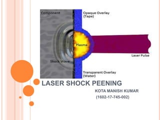
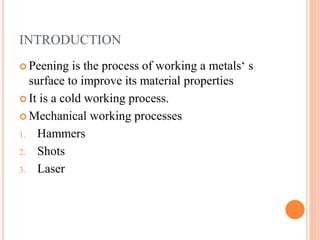
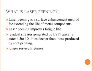
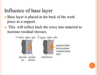
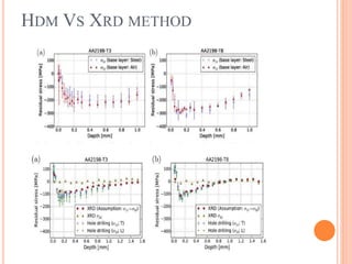
LASER SHOCK PEENING
KOTA MANISH KUMAR
(1602-17-745-002)
CONTENTS
 Introduction
 Literature Review
 Experimental Setup
 Working Process
 What are residual stresses
 Incremental hole drilling method
 Factors influencing residual stresses
 Advantages
 Conclusion
 References
INTRODUCTION
 Peening is the process of working a metals‘ s
surface to improve its material properties
 It is a cold working process.
 Mechanical working processes
1. Hammers
2. Shots
3. Laser
WHAT IS LASER PEENING?
 Laser peening is a surface enhancement method
for extending the life of metal components
 Laser peening improves fatigue life
 residual stresses generated by LSP typically
extend 5to 10 times deeper than those produced
by shot peening.
 longer service lifetimes
RESIDUAL STRESS ANALYSIS ON
TITANIUM ALLOY TC4 BY LASER
SHOCK PEENING
 This test was performed by jun hong li ,he is
from china.
 He is done LSP test on TC4 material
 the residual stresses using x-ray stress analyser
 Results indicates that there was large residual
stresses are induced on the surface of material.
PARAMETRIC STUDY ON SINGLE SHOT
AND OVERLAPPING LASER SHOCK
PEENING ON VARIOUS METALS VIA
MODELLING AND EXPERIMENTS
 This paper is written by yunfeng cao and yung
c.shin.
this experiment performed on 4140 steel and TI-
6AL-4V materials
 These are underwater confinement process
 And he used 3-d finite element for analyse
residual stresses in the materials
AN ANALYTICAL MODEL TO PREDICT
RESIDUAL STRESS FIELD INDUCED BY
LASER SHOCK PEENING
 This paper was published by yongxiang hu and
zheqiang yao and jun hu
 He proposed a complete analytical model of LSP
 He used FEM to calculate residual stresses in the
material
EXPERIMENTAL AND NUMERICAL
INVESTIGATION OF RESIDUAL
STRESSES IN LASER PEENED AA2198
 This paper was published by s.keller,s.chupakhin,
p.staron,e.maawad,n.kashaev
 Lsp is done on AA2198 material
 Experimental and numerical investigation are done
using different investigating models
 Using hole drilling method and x-ray diffraction test
FINITE ELEMENT ANALYSIS OF
VARIATION IN RESIDUAL STRESS
DISTRIBUTION IN LASER SHOCK
PEENING OF STEELS
 This paper was published rohit voothaluru and
c.Richard liu gary j.cheng
 This experiment was done on 1053STEEL &
52100 AISI STEELS
 By using ansys software he compared residual
stresses of 1053 STEEL and 52100 AISI
STEELS
EXPERIMENTAL SETUP
EXPERIMENTAL DETAILS
 Laser characteristics
1. Neodymium glass (Nd) laser (1054 nm wavelength)
2. 0.6 - 5 J energy per pulse
3. 1 - 3mm spot diameter
4. 2.78- 25GW/cm2 power density
 Opaque used
1. Paint
2. Tape
 Coolant used
1. water
• Specimen used
1. AA2198-T3, AA2198-T5
2. Specimen thickness : 3.2 mm
• Base layer used:
1. Steel plate
2. Air
•PROCEDURE
 A high-energy, short-duration laser pulse
produces a rapidly expanding plasma burst on
the part surface
 The rapid rise of pressure generates a powerful
compressive shockwave that propagates into the
material.
TYPICAL LSP PROCESSING PARAMETERS FROM THE LITERATURE USED FOR
DIFFERENT MATERIALS WITH CONCLUDING REMARKS.
WHAT ARE RESIDUAL STRESSES?
 Residual stresses are stresses that remain in a
solid material after the original cause of the
stresses has been removed
 Residual stress may be desirable or undesirable
 Undesirable residual stresses cause premature
failures
WHY ARE RESIDUAL STRESSES
BENEFICIAL?
 When a component is enhanced with
compressive residual stresses, it can withstand
greater tensile forces before cracking and failure
occur.
 buffer against tensile strain,
 deeper compressive stresses inhibit crack
initiation
METHODS TO FIND RESIDUAL
STRESSES
 Nano-indentation,
 X-ray diffraction,
 metallographic microscope,
 SEM,
 TEM
 Incremental hole drilling method
 Fem
INCREMENTAL HOLE DRILLING
METHOD
 Residual stresses were determined by the
measurement system Prism from Stress-tech by
1. electronic speckle pattern interferometry
(ESPI) or Strain gauges.
1. Drilling a hole incrementally.
2. Measurement of the surface deformation after
each increment using ESPI or Strain gauges
3. Calculation of the residual stresses from surface
deformations(Integral method)
ESPI SETUP
STRAIN GUAGE SETUP
FACTORS INFLUENCING RESIDUAL
STRESSES DURING EXPERIMENT
 Temper condition
 Focal size
 Laser power density
 Base layer
TEMPER CONDITION
FOCAL SIZE
• Low focus size
1. high overlapping stresses
2. spherical wavefront
• High focus size
1. high depth of penetration
2. linear wave front
Laser power density
1. Higher power density leads to high pressure pulse
irrespective of pulse energy
Influence of base layer
 Base layer is placed at the back of the work
piece as a support.
 This will reflect back the wave into material to
increase residual stresses.
Influence of specimen thickness
1. Increase in the thickness the shock wave
intensity decreases at the end of plate
2. Reflected shock wave intensity also decreases
X-RAY DIFFRACTIONS TEST
 The photon energy: 87.1 kev
 Wave length:0.1419 Aº
 Pixel size :200μm
 Beam is 1.5 mt from work-piece
HDM VS XRD METHOD
ADVANTAGES
o increases the strength
o high fatigue resistance
o High wear properties
o Low cold work
DIS-ADVANTAGES
 High capital cost
 Repeated coating
 Difficult to control process variables
APPLICATIONS
 Engine components
 Turbine, fan, and compressor blades
 Bulkheads, wing attachments, flight control
mechanisms, wheels
 Brakes, landing gear
 Welded titanium and aluminum components for
improved reliability
 Welded aging aircraft parts for improved
reliability
CONCLUSION
 As the LSP power density increased, the residual
compressive stresses on the surface were also
increased.
 fatigue resistance of material would be greatly
improved
 Laser shock processing can make high residual
compressive stress on the surface and deep
inside of the material.
 Compressive stresses decreased gradually with
the depth increased,

Laser shock peening presentation

  • 1.
    LASER SHOCK PEENING KOTAMANISH KUMAR (1602-17-745-002)
  • 2.
    CONTENTS  Introduction  LiteratureReview  Experimental Setup  Working Process  What are residual stresses  Incremental hole drilling method  Factors influencing residual stresses  Advantages  Conclusion  References
  • 3.
    INTRODUCTION  Peening isthe process of working a metals‘ s surface to improve its material properties  It is a cold working process.  Mechanical working processes 1. Hammers 2. Shots 3. Laser
  • 4.
    WHAT IS LASERPEENING?  Laser peening is a surface enhancement method for extending the life of metal components  Laser peening improves fatigue life  residual stresses generated by LSP typically extend 5to 10 times deeper than those produced by shot peening.  longer service lifetimes
  • 5.
    RESIDUAL STRESS ANALYSISON TITANIUM ALLOY TC4 BY LASER SHOCK PEENING  This test was performed by jun hong li ,he is from china.  He is done LSP test on TC4 material  the residual stresses using x-ray stress analyser  Results indicates that there was large residual stresses are induced on the surface of material.
  • 6.
    PARAMETRIC STUDY ONSINGLE SHOT AND OVERLAPPING LASER SHOCK PEENING ON VARIOUS METALS VIA MODELLING AND EXPERIMENTS  This paper is written by yunfeng cao and yung c.shin. this experiment performed on 4140 steel and TI- 6AL-4V materials  These are underwater confinement process  And he used 3-d finite element for analyse residual stresses in the materials
  • 7.
    AN ANALYTICAL MODELTO PREDICT RESIDUAL STRESS FIELD INDUCED BY LASER SHOCK PEENING  This paper was published by yongxiang hu and zheqiang yao and jun hu  He proposed a complete analytical model of LSP  He used FEM to calculate residual stresses in the material
  • 8.
    EXPERIMENTAL AND NUMERICAL INVESTIGATIONOF RESIDUAL STRESSES IN LASER PEENED AA2198  This paper was published by s.keller,s.chupakhin, p.staron,e.maawad,n.kashaev  Lsp is done on AA2198 material  Experimental and numerical investigation are done using different investigating models  Using hole drilling method and x-ray diffraction test
  • 9.
    FINITE ELEMENT ANALYSISOF VARIATION IN RESIDUAL STRESS DISTRIBUTION IN LASER SHOCK PEENING OF STEELS  This paper was published rohit voothaluru and c.Richard liu gary j.cheng  This experiment was done on 1053STEEL & 52100 AISI STEELS  By using ansys software he compared residual stresses of 1053 STEEL and 52100 AISI STEELS
  • 10.
  • 11.
    EXPERIMENTAL DETAILS  Lasercharacteristics 1. Neodymium glass (Nd) laser (1054 nm wavelength) 2. 0.6 - 5 J energy per pulse 3. 1 - 3mm spot diameter 4. 2.78- 25GW/cm2 power density  Opaque used 1. Paint 2. Tape  Coolant used 1. water
  • 12.
    • Specimen used 1.AA2198-T3, AA2198-T5 2. Specimen thickness : 3.2 mm • Base layer used: 1. Steel plate 2. Air
  • 13.
    •PROCEDURE  A high-energy,short-duration laser pulse produces a rapidly expanding plasma burst on the part surface  The rapid rise of pressure generates a powerful compressive shockwave that propagates into the material.
  • 14.
    TYPICAL LSP PROCESSINGPARAMETERS FROM THE LITERATURE USED FOR DIFFERENT MATERIALS WITH CONCLUDING REMARKS.
  • 15.
    WHAT ARE RESIDUALSTRESSES?  Residual stresses are stresses that remain in a solid material after the original cause of the stresses has been removed  Residual stress may be desirable or undesirable  Undesirable residual stresses cause premature failures
  • 16.
    WHY ARE RESIDUALSTRESSES BENEFICIAL?  When a component is enhanced with compressive residual stresses, it can withstand greater tensile forces before cracking and failure occur.  buffer against tensile strain,  deeper compressive stresses inhibit crack initiation
  • 17.
    METHODS TO FINDRESIDUAL STRESSES  Nano-indentation,  X-ray diffraction,  metallographic microscope,  SEM,  TEM  Incremental hole drilling method  Fem
  • 18.
    INCREMENTAL HOLE DRILLING METHOD Residual stresses were determined by the measurement system Prism from Stress-tech by 1. electronic speckle pattern interferometry (ESPI) or Strain gauges. 1. Drilling a hole incrementally. 2. Measurement of the surface deformation after each increment using ESPI or Strain gauges 3. Calculation of the residual stresses from surface deformations(Integral method)
  • 19.
  • 20.
  • 21.
    FACTORS INFLUENCING RESIDUAL STRESSESDURING EXPERIMENT  Temper condition  Focal size  Laser power density  Base layer
  • 22.
  • 23.
    FOCAL SIZE • Lowfocus size 1. high overlapping stresses 2. spherical wavefront • High focus size 1. high depth of penetration 2. linear wave front Laser power density 1. Higher power density leads to high pressure pulse irrespective of pulse energy
  • 25.
    Influence of baselayer  Base layer is placed at the back of the work piece as a support.  This will reflect back the wave into material to increase residual stresses.
  • 26.
    Influence of specimenthickness 1. Increase in the thickness the shock wave intensity decreases at the end of plate 2. Reflected shock wave intensity also decreases
  • 27.
    X-RAY DIFFRACTIONS TEST The photon energy: 87.1 kev  Wave length:0.1419 Aº  Pixel size :200μm  Beam is 1.5 mt from work-piece
  • 28.
    HDM VS XRDMETHOD
  • 29.
    ADVANTAGES o increases thestrength o high fatigue resistance o High wear properties o Low cold work
  • 30.
    DIS-ADVANTAGES  High capitalcost  Repeated coating  Difficult to control process variables
  • 31.
    APPLICATIONS  Engine components Turbine, fan, and compressor blades  Bulkheads, wing attachments, flight control mechanisms, wheels  Brakes, landing gear  Welded titanium and aluminum components for improved reliability  Welded aging aircraft parts for improved reliability
  • 32.
    CONCLUSION  As theLSP power density increased, the residual compressive stresses on the surface were also increased.  fatigue resistance of material would be greatly improved  Laser shock processing can make high residual compressive stress on the surface and deep inside of the material.  Compressive stresses decreased gradually with the depth increased,