Transmission management in BSS is a feature used in managing the Base Station Subsystem transmission system functions such as supervision, alarms, statistics
and settings. The network element mainly responsible for transmission management in BSS is the Base Station Controller (BSC).
Transmission management functionalities make it possible for the operators to manage the transmission equipment remotely from the BSC or from Nokia
NetAct integrated network management system, which simplifies network maintenance and operation. Supervision functions help minimise the time spent in maintenance, and statistics collection helps the operators analyse and optimise
the use of their transmission equipment. Moreover, new software can be downloaded in a way that does not interfere with the traffic.
Hardware and software requirements BSS transmission network elements
BSS transmission management functionalities Transmission parameters Transmission alarms
Transmission measurements
2.Hardware and software requirements
There are no specific hardware or software requirements for the transmission management functionalities. However, the type of the BTS poses certain
limitations.
The BTS type specific functionalities are listed in the table below.
More details about the functionalities can be found in BSS transmission management functionalities .
Polling list sending with priority is a functionality used in positioning. To ensure accurate positioning calculations, the LMU unit must supply Radio Interface Timing System (RIT) information to the network faster than the normal Q1 polling is able to do. Faster LMU polling is achieved by defining a Q1 polling
priority for each Q1 device, with the LMU having the highest priority. For more information see Location Services .
3.BSS transmission network elements
The base Station Subsystem (BSS) consists of at least one Base Station Controller (BSC) and its Base Transceiver Stations (BTS). The Transcoder Submultiplexer
(TCSM) is also part of the BSS although it is actually located in the MSC site. The three basic configurations (topologies) for transmission between the BSC and
the BTSs are: point-to-point connection
multidrop chain multidrop loop
In point-to-point configuration each BTS is connected directly to the BSC. In the multidrop chain, BTSs form a chain and the first BTS in the network is connected directly to the BSC. In the loop connection, the BTSs form a loop where the first and the last BTS in the loop are connected directly to the BSC via a crossconnecting node. The topology used depends on a number of factors such as the distance between the BSC and the BTS, the number of transceivers (TRXs) used at a particular BTS site and the signalling channel rate between the BSC and the\ BTS. Usually the topology used is a mixture of the three basic topologies. Formore information on the topologies, refer to Nokia BSS Transmission\Configuration .
For a long time, IP Multimedia Subsystem (IMS) was nothing more than just a revolutionary idea to move all existing teleservices, including telephony to the PS domain of the mobile network and to create a vast variety of brand new teleservices totally based on end-to-end IP connectivity. Today, thanks to Rich Communication Suite-enhanced (RCS-e) initiative, there is a clear path and agreement on how to turn IMS into practice. RCS-e ensures that the same initial subset of IMS services will be introduced by all operators, infrastructure and terminal vendors and will work smoothly also in inter-operator scenarios. The course explains RCS-e services, underpaying IMS architecture and basic procedures and their impact on existing operator infrastructure.
This chapter will cover how to configure, manage, and troubleshoot VLANs and
VLAN trunks. It will also examine security considerations and strategies relating
to VLANs and trunks, and best practices for VLAN design.
NSA advisory about state sponsored cybersecurity threatsRonald Bartels
Chinese State-Sponsored Actors Exploit Publicly Known Vulnerabilities. This advisory provides Common Vulnerabilities and Exposures (CVEs) known to be recently leveraged, or scanned-for, by Chinese state-sponsored cyber actors to enable successful hacking operations against a multitude of victim networks.
Problem management foundation - IntroductionRonald Bartels
Problem management is typically defined as an aggregated process that analyses issues within an organisation and provides causation to adverse events and situations.
A key element is how a major incident is handled as this is one of the most crucial processes for an enterprise. A major incident which is one with a significant negative business consequences needs to be handled with a well defined process which is not currently clearly defined in existing methodologies.
This course addresses how an enterprise, with a focus on IT, needs to handle the major incident process which includes those outages and failures that are on the immediate horizon of any enterprise.
It also deals with the aspects of dealing with problems with an organization in a generic fashion including supporting methodologies and processes.
An overview of crisis management
What is crisis management
Entities involved in crisis management
Incidents, problems and Major incidents (in an ITIL context)
Vital Business Functions
The causes of a major incident are a problem
Other problems are highlighted by the manner in which the major incident is handled
Refer the Major Incident Classification Tool in the Appendix
Tool is used to ensure the correct classification of a Major incident and that all details are captured
Pilots are trained on simulators because they can not afford to deal with life threatening events in the air by way of experimentation
The diligence applied in the aviation industry is seldom duplicated with Information Technology being a case in point
Simulation is crucial to the successful resolution of a crisis
A disaster recovery test is an example of a simulation involving crisis management
The simulation exercises should cover
Media communications
Being able to avoid inconsistent communications
Social media interactions
Desktop exercises
Full blown scenario simulations (replay of known errors)
Co-ordination of all stakeholders
Deming wheel: Made popular by Dr W. Edwards Deming, based on work by Shewhart.
Concepts originate from scientific method and the works of Bacon.
Plan to improve service management by determining what is going wrong (that is identify the problems), and then suggest resolutions.
Do changes designed to solve the problems on a small and incremental scale first. This minimizes disruption to Live while testing whether the changes are workable
Builder.ai Founder Sachin Dev Duggal's Strategic Approach to Create an Innova...Ramesh Iyer
In today's fast-changing business world, Companies that adapt and embrace new ideas often need help to keep up with the competition. However, fostering a culture of innovation takes much work. It takes vision, leadership and willingness to take risks in the right proportion. Sachin Dev Duggal, co-founder of Builder.ai, has perfected the art of this balance, creating a company culture where creativity and growth are nurtured at each stage.
UiPath Test Automation using UiPath Test Suite series, part 4DianaGray10
Welcome to UiPath Test Automation using UiPath Test Suite series part 4. In this session, we will cover Test Manager overview along with SAP heatmap.
The UiPath Test Manager overview with SAP heatmap webinar offers a concise yet comprehensive exploration of the role of a Test Manager within SAP environments, coupled with the utilization of heatmaps for effective testing strategies.
Participants will gain insights into the responsibilities, challenges, and best practices associated with test management in SAP projects. Additionally, the webinar delves into the significance of heatmaps as a visual aid for identifying testing priorities, areas of risk, and resource allocation within SAP landscapes. Through this session, attendees can expect to enhance their understanding of test management principles while learning practical approaches to optimize testing processes in SAP environments using heatmap visualization techniques
What will you get from this session?
1. Insights into SAP testing best practices
2. Heatmap utilization for testing
3. Optimization of testing processes
4. Demo
Topics covered:
Execution from the test manager
Orchestrator execution result
Defect reporting
SAP heatmap example with demo
Speaker:
Deepak Rai, Automation Practice Lead, Boundaryless Group and UiPath MVP
Slack (or Teams) Automation for Bonterra Impact Management (fka Social Soluti...Jeffrey Haguewood
Sidekick Solutions uses Bonterra Impact Management (fka Social Solutions Apricot) and automation solutions to integrate data for business workflows.
We believe integration and automation are essential to user experience and the promise of efficient work through technology. Automation is the critical ingredient to realizing that full vision. We develop integration products and services for Bonterra Case Management software to support the deployment of automations for a variety of use cases.
This video focuses on the notifications, alerts, and approval requests using Slack for Bonterra Impact Management. The solutions covered in this webinar can also be deployed for Microsoft Teams.
Interested in deploying notification automations for Bonterra Impact Management? Contact us at sales@sidekicksolutionsllc.com to discuss next steps.
The Art of the Pitch: WordPress Relationships and SalesLaura Byrne
Clients don’t know what they don’t know. What web solutions are right for them? How does WordPress come into the picture? How do you make sure you understand scope and timeline? What do you do if sometime changes?
All these questions and more will be explored as we talk about matching clients’ needs with what your agency offers without pulling teeth or pulling your hair out. Practical tips, and strategies for successful relationship building that leads to closing the deal.
LF Energy Webinar: Electrical Grid Modelling and Simulation Through PowSyBl -...DanBrown980551
Do you want to learn how to model and simulate an electrical network from scratch in under an hour?
Then welcome to this PowSyBl workshop, hosted by Rte, the French Transmission System Operator (TSO)!
During the webinar, you will discover the PowSyBl ecosystem as well as handle and study an electrical network through an interactive Python notebook.
PowSyBl is an open source project hosted by LF Energy, which offers a comprehensive set of features for electrical grid modelling and simulation. Among other advanced features, PowSyBl provides:
- A fully editable and extendable library for grid component modelling;
- Visualization tools to display your network;
- Grid simulation tools, such as power flows, security analyses (with or without remedial actions) and sensitivity analyses;
The framework is mostly written in Java, with a Python binding so that Python developers can access PowSyBl functionalities as well.
What you will learn during the webinar:
- For beginners: discover PowSyBl's functionalities through a quick general presentation and the notebook, without needing any expert coding skills;
- For advanced developers: master the skills to efficiently apply PowSyBl functionalities to your real-world scenarios.
Accelerate your Kubernetes clusters with Varnish CachingThijs Feryn
A presentation about the usage and availability of Varnish on Kubernetes. This talk explores the capabilities of Varnish caching and shows how to use the Varnish Helm chart to deploy it to Kubernetes.
This presentation was delivered at K8SUG Singapore. See https://feryn.eu/presentations/accelerate-your-kubernetes-clusters-with-varnish-caching-k8sug-singapore-28-2024 for more details.
DevOps and Testing slides at DASA ConnectKari Kakkonen
My and Rik Marselis slides at 30.5.2024 DASA Connect conference. We discuss about what is testing, then what is agile testing and finally what is Testing in DevOps. Finally we had lovely workshop with the participants trying to find out different ways to think about quality and testing in different parts of the DevOps infinity loop.
Kubernetes & AI - Beauty and the Beast !?! @KCD Istanbul 2024Tobias Schneck
As AI technology is pushing into IT I was wondering myself, as an “infrastructure container kubernetes guy”, how get this fancy AI technology get managed from an infrastructure operational view? Is it possible to apply our lovely cloud native principals as well? What benefit’s both technologies could bring to each other?
Let me take this questions and provide you a short journey through existing deployment models and use cases for AI software. On practical examples, we discuss what cloud/on-premise strategy we may need for applying it to our own infrastructure to get it to work from an enterprise perspective. I want to give an overview about infrastructure requirements and technologies, what could be beneficial or limiting your AI use cases in an enterprise environment. An interactive Demo will give you some insides, what approaches I got already working for real.
Neuro-symbolic is not enough, we need neuro-*semantic*Frank van Harmelen
Neuro-symbolic (NeSy) AI is on the rise. However, simply machine learning on just any symbolic structure is not sufficient to really harvest the gains of NeSy. These will only be gained when the symbolic structures have an actual semantics. I give an operational definition of semantics as “predictable inference”.
All of this illustrated with link prediction over knowledge graphs, but the argument is general.
GDG Cloud Southlake #33: Boule & Rebala: Effective AppSec in SDLC using Deplo...James Anderson
Effective Application Security in Software Delivery lifecycle using Deployment Firewall and DBOM
The modern software delivery process (or the CI/CD process) includes many tools, distributed teams, open-source code, and cloud platforms. Constant focus on speed to release software to market, along with the traditional slow and manual security checks has caused gaps in continuous security as an important piece in the software supply chain. Today organizations feel more susceptible to external and internal cyber threats due to the vast attack surface in their applications supply chain and the lack of end-to-end governance and risk management.
The software team must secure its software delivery process to avoid vulnerability and security breaches. This needs to be achieved with existing tool chains and without extensive rework of the delivery processes. This talk will present strategies and techniques for providing visibility into the true risk of the existing vulnerabilities, preventing the introduction of security issues in the software, resolving vulnerabilities in production environments quickly, and capturing the deployment bill of materials (DBOM).
Speakers:
Bob Boule
Robert Boule is a technology enthusiast with PASSION for technology and making things work along with a knack for helping others understand how things work. He comes with around 20 years of solution engineering experience in application security, software continuous delivery, and SaaS platforms. He is known for his dynamic presentations in CI/CD and application security integrated in software delivery lifecycle.
Gopinath Rebala
Gopinath Rebala is the CTO of OpsMx, where he has overall responsibility for the machine learning and data processing architectures for Secure Software Delivery. Gopi also has a strong connection with our customers, leading design and architecture for strategic implementations. Gopi is a frequent speaker and well-known leader in continuous delivery and integrating security into software delivery.
JMeter webinar - integration with InfluxDB and GrafanaRTTS
Watch this recorded webinar about real-time monitoring of application performance. See how to integrate Apache JMeter, the open-source leader in performance testing, with InfluxDB, the open-source time-series database, and Grafana, the open-source analytics and visualization application.
In this webinar, we will review the benefits of leveraging InfluxDB and Grafana when executing load tests and demonstrate how these tools are used to visualize performance metrics.
Length: 30 minutes
Session Overview
-------------------------------------------
During this webinar, we will cover the following topics while demonstrating the integrations of JMeter, InfluxDB and Grafana:
- What out-of-the-box solutions are available for real-time monitoring JMeter tests?
- What are the benefits of integrating InfluxDB and Grafana into the load testing stack?
- Which features are provided by Grafana?
- Demonstration of InfluxDB and Grafana using a practice web application
To view the webinar recording, go to:
https://www.rttsweb.com/jmeter-integration-webinar
JMeter webinar - integration with InfluxDB and Grafana
LANNET LANswitch Plus LSA+ ATM Access Switch
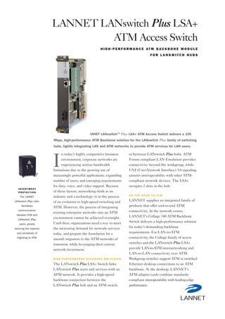
1. I N V E S T M E N T
P R O T E C T I O N
The LANNET
LANswitch Plus LSA+
facilitates
communication
between ATM and
LANswitch Plus
users, greatly
reducing the expense
and complexity of
migrating to ATM.
n today’s highly competitive business
environment, corporate networks are
experiencing serious bandwidth
limitations due to the growing use of
increasingly powerful applications, expanding
number of users, and emerging requirements
for data, voice, and video support. Because
of these factors, networking–both as an
industry and a technology–is in the process
of an evolution to high-speed switching and
ATM. However, the process of integrating
existing enterprise networks into an ATM
environment cannot be achieved overnight.
Until then, organizations need a way to meet
the increasing demand for network services
today, and prepare the foundation for a
smooth migration to the ATM networks of
tomorrow, while leveraging their current
network investment.
H I G H - P E R F O R M A N C E B A C K B O N E S W I T C H I N G
The LANswitch Plus LSA+ Switch links
LANswitch Plus users and services with an
ATM network. It provides a high-speed
backbone connection between the
LANswitch Plus hub and an ATM switch,
or between LANswitch Plus hubs. ATM
Forum compliant LAN Emulation provides
connectivity beyond the workgroup, while
UNI (User-Network Interface) 3.0 signaling
ensures interoperability with other ATM-
compliant network devices. The LSA+
occupies 2 slots in the hub.
O N T H E R O A D T O AT M
LANNET supplies an integrated family of
products that offer end-to-end ATM
connectivity. At the network center,
LANNET’s Collage 740 ATM Backbone
Switch delivers a high-performance solution
for today’s demanding backbone
requirements. For LAN-to-ATM
connectivity, the Collage family of access
switches and the LANswitch Plus LSA+
provide LAN-to-ATM internetworking and
LAN-to-LAN connectivity over ATM.
Workgroup switches support ATM or switched
Ethernet desktop connections to an ATM
backbone. At the desktop, LANNET’s
ATM adapter cards combine standards-
compliant interoperability with leading-edge
performance.
LANNET LANswitch Plus LSA+
ATM Access Switch
H I G H - P E R F O R M A N C E AT M B A C K B O N E M O D U L E
F O R L A N S W I T C H H U B S
The LANNET LANswitch™ Plus LSA+ ATM Access Switch delivers a 155
Mbps, high-performance ATM Backbone solution for the LANswitch Plus family of switching
hubs, tightly integrating LAN and ATM networks to provide ATM services for LAN users.
I
2. LANNET gives network users the
flexibility to adopt ATM at their own pace.
The LSA+ integrates easily into existing
switched Ethernet, Fast Ethernet
and–uniquely–FDDI networks. This
integration allows organizations to
selectively enhance legacy network
performance to ATM levels in response to
increasing user needs.
E A S Y I N T E G R AT I O N W I T H AT M
Performance-boosting LANswitch Plus
modules, like the LSA+, plug directly into
the LANswitch Plus chassis, allowing
customers to deploy ATM technology where
it is needed most by simply inserting
modules into the hub.
The result is an economical, gradual
migration path that leverages your investment
in existing network infrastructure to the
fullest.
This built-in flexibility, together with
ATM value-added services, makes
LANNET LANswitch Plus the first hub in
the industry providing easy coexistence and
migration from shared LANs to switched
LANs to ATM.
AT M S E R V I C E S F O R L A N U S E R S
The LSA+ is the ideal way to combine the
performance, scalability and manageability
of LANswitch Plus networks, with the
benefits of an ATM backbone. ATM and
LANswitch Plus value-added services
operate end-to-end across LAN and ATM
networks, providing LAN users with ATM-
like services today.
LANswitch Plus congestion
management, like ATM flow control, puts
an end to lost packets, while LANswitch
packet priority will map directly to ATM
Quality of Service. These services guarantee
network performance and a rock-solid
foundation for delay-sensitive multi-media
applications.
A P P L I C AT I O N F L E X I B I L I T Y
The LANswitch Plus LSA+ supports a
collapsed backbone configuration to an
ATM backbone switch. The diagram
demonstrates the migration of a building
network to ATM. Each floor contains an
ATM access switch, and all floors are linked
through a central ATM backbone switch.
Workgroups span the enterprise—with
members in the same virtual LAN residing
LANNET
LANswitch Plus
LSA+ ATM
Access Switch
The LANswitch Plus LSA+
connects to an ATM backbone
switch,and can also form an
Inter-Switch Link to another
LSA+, or to a Collage 530
Ethernet to ATM Access Switch.
3. Direct ATM connection between LSA+
modules to form an Inter-Switch Link (ISL)
allows the design of cost-effective ATM
backbones.
An ISL connection between LSA+
modules allows a collapsed backbone to be
built using multiple LSA+ modules in a
LANswitch Plus hub. An LSA+ based
connection can then be made from the
LANswitch Plus hub to a backbone switch at
the center of the enterprise network.
The LSA+ can also be directly
connected to the Collage 530 Ethernet to
ATM Access Switch, allowing for a gradual
implementation of ATM.
By seamlessly integrating LANswitch
Plus and ATM technologies, the LSA+
ensures that clients and servers across the
campus network receive the bandwidth they
require, without the need for changes to
existing network installations.
V I R T U A L L A N S T H AT S PA N T H E B A C K B O N E
With the LSA+, network managers can
define Virtual LANs that span the campus
network. Virtual LANs allow users in shared
and switched LANs to participate in the
same logical workgroup as ATM users and
resources. The LSA+ can transfer up to 256
Virtual LANs across the backbone and
creates a LAN Emulation Client for every
emulated LAN. LANNET’s Montage™
Network Management System makes
adding, changing and deleting Virtual LANs
as easy as point-and-click.
F U L LY M A N A G E A B L E
To keep a switched network running
smoothly, network managers must be able
to effectively monitor and troubleshoot the
switch. The LSA+ is fully monitored and
managed by SMON™, LANNET’s RMON
switch monitoring application which works
in conjunction with Montage, LANNET’s
comprehensive SNMP-based Network
Management System.
SMON provides full monitoring and
reporting of ATM traffic statistics received
and transmitted by the LSA+. SMON
passively monitors all traffic traversing the
multi-Giga Cellenium switching backplane,
giving network managers a top-down
perspective of activity in the switched
network.
Top-down switch management employs
a multitier methodology, beginning with a
global view of switch traffic and progressing
to specific views of individual switch ports–
such as the LSA+ switch port, and their
hosts. Using the global view, network
managers can quickly pinpoint areas of
interest in the switch, and then zoom in on
specific hosts or individual sessions in order
to analyze them in more detail.
Montage and SMON are fully integrated
with such popular management platforms as
HP OpenView/UNIX, HP OpenView/
Windows, and IBM NetView.
S TA N D A R D S - C O M P L I A N T L A N E M U L AT I O N
The LANswitch Plus LSA+ includes all the
functionality necessary to provide
transparent internetworking. ATM Forum-
compliant LAN Emulation built into every
LANswitch Plus LSA+ assures seamless
connectivity across the entire network. LAN
Emulation transparently connects LANs to
ATM by allowing existing network protocols
(such as IP, IPX, Appletalk, or DECnet) to
run unchanged over the ATM network.
LANNET
LANswitch Plus
LSA+ ATM
Access Switch
4. C U S T O M E R S U P P O R T W I T H O U T L I M I T S
The LSA+ ATM Access switch is backed
by LANNET’s expertise in networking and
a worldwide network of Value Added
Resellers.
Customers can also download
information from the LANNET World
Wide Web home page
(http://www.lannet.com).
The LSA+ module comes with a one-
year hardware warranty.
P R O D U C T S P E C I F I C AT I O N S
I N T E R FA C E S
ATM: 155.52 Mbps
SONET OC-3C or SDH STM-1
Multimode SC fiber connector
Duplex 62.5/125µ (2km, 1300nm)
Console: RJ45 connector. RS 232C
F U N C T I O N S
ATM Switching: ATM Forum UNI 3.0, upgradeable.
ATM cell processing per ANSI
T1S1.5/92-002R3, ITU I361
Up to 1024 VCIs
LAN Emulation: Version 1.0 proxy LAN Emulation
Transparent Bridging Client
Signaling: Q.2391 standard
AAL Support: AAL5
P H Y S I C A L C H A R A C T E R I S T I C S
Dimensions (h,w,d): 240mm x 40mm x 230mm
Weight: 0.9 kg
P O W E R R E Q U I R E M E N T S
Max Power
Dissipation: 5.3 A at 5.0 V DC
E N V I R O N M E N TA L
Operating
Temperature: 0-40 degrees Celsius
Humidity: 5% to 95% non-condensing
A G E N C Y A P P R O VA L
EMI: Emission: FCC Part 15, subpart J,
class B; CE,
EN55022 class B
Immunity: Meets EN50082-1
F R O N T PA N E L I N D I C AT O R S
LED indicators show the Transmit, Receive and Error
status for the switch port and ATM port, and Run, Test
and Error for the module operating system.
N E T W O R K M A N A G E M E N T
Graphical
Management: Montage version 4.0 or higher
SNMP-based Agent: MIB II (RFC 1213),
MIB II Extension (RFC 1573)
O R D E R I N G I N F O R M AT I O N
P a r t N o . D e s c r i p t i o n
860204 LSA+ LANswitch to ATM
Access Switch
Specifications subject to change without notice.
LANNET
LANswitch LSA+
ATM Access
Switch
LANNET, the LANNET logo, Cellenium, LANswitch, Montage, MultiNet, SMON, TerrainMaster, and Visage are trademarks, and in some jurisdictions may be registered
trademarks, of LANNET Ltd., Madge Networks or its affiliated companies. Other trademarks appearing in this document are the property of their respective owners.
143014 Rev. 0 2/98
Israel
LANNET Ltd.
Atidim Technology Park
Building 3
Tel-Aviv 61131
Israel
Tel +972 3 645 8458
Fax +972 3 648 7146
http://www.lannet.com
USA
LANNET Inc.
150 Knowles Ave.
Los Gatos, CA 95032
USA
Tel 1-888-ETHERNET
(408) 871-4000
Fax (408) 871-4100
http://www.lannet.com
Other Offices
Benelux
Brazil
China
France
Germany
Honk Kong
Iberia
Italy
Japan
Korea
Mexico
Republic of S. Africa
Singapore
Sweden
Switzerland
United Kingdom