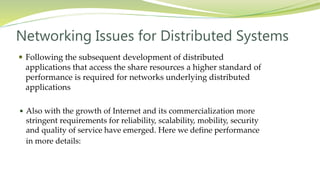
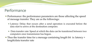
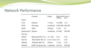
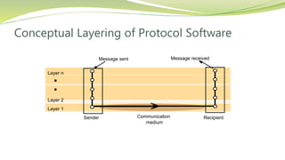
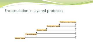
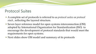
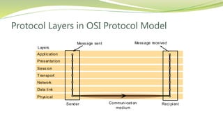
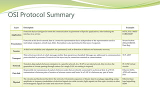
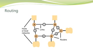
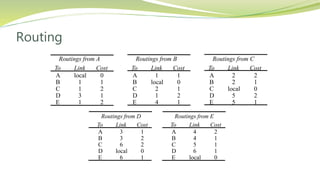
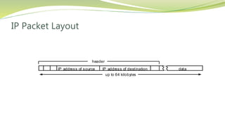
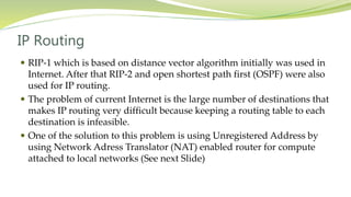
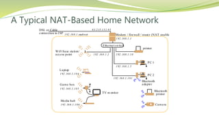
Presentation
Topics
 Networking Issues for Distributed Systems
 Basics of Networking
 Internet Protocols
Networking Issues for Distributed Systems
 Following the subsequent development of distributed
applications that access the share resources a higher standard of
performance is required for networks underlying distributed
applications
 Also with the growth of Internet and its commercialization more
stringent requirements for reliability, scalability, mobility, security
and quality of service have emerged. Here we define performance
in more details:
Performance
 Performance: the performance parameters are those affecting the speed
of message transfer. They are as the followings:
 Latency: Delay that occurs after a send operation is executed before the
data start to arrive at the destination computer.
 Data transfer rate: Speed at which the data can be transferred between two
computers once transmission has begun.
 Thus the transfer time for a message containing length bit is: latency +
length/data transfer rate
Performance
 The equation for message transfer rate is only valid if the length of
message does not exceed a maximum that is determined by the
underlying network technology. Longer messages have to be
segmented and transmission time is sum of the times for segments.
 For example if message transfer is performed between two processes in
a distributed system since messages are small, latency has greater
significance than transfer rate in that case.
Performance
 The total system bandwidth of a network is a measure of throughput
 The throughput is the total volume of traffic that can be transferred
across the network in a given time.
 In many Local Are Networks (LAN) such as Ethernet system
bandwidth is the same as the data transfer rate.
 In most Wide Area Networks (WAN) since messages can be transferred
in different channels simultaneously, total system bandwidth is
different from transfer rate.
 Next slide shows some networks performance
Network Performance
Example Range Bandwidth
(Mbps)
Latency
(ms)
Wired:
LAN Ethernet 1-2 kms 10-1000 1-10
WAN IP routing worldwide 0.010-600 100-500
MAN ATM 250 kms 1-150 10
Internetwork Internet worldwide 0.5-600 100-500
Wireless:
WPAN Bluetooth (802.15.1) 10 - 30m 0.5-2 5-20
WLAN WiFi (IEEE 802.11) 0.15-1.5 km 2-54 5-20
WMAN WiMAX (802.16) 550 km 1.5-20 5-20
WWAN GSM, 3G phone nets worldwide 0.01-02 100-500
Protocol layers
 Network software is arranged in a hierarchy of layers
 Data is sent to sender through different layers
 Each layer of network software communicates with the layers above
and below it. See the next slide
 The protocol types of the above layers are included in the packets sent
by the sender to enable the protocol stack at the receiver for selecting
the correct software component to unpack the packets. See
encapsulation slide
Conceptual Layering of Protocol Software
Layer n
Layer 2
Layer 1
Message sent Message received
Communication
medium
Sender Recipient
Encapsulation in layered protocols
Presentation header
Application-layer message
Session header
Transport header
Network header
Protocol Suites
 A complete set of protocols is referred to as protocol suites or protocol
stack , reflecting the layered structure.
 Seven layer reference model for open systems interconnection (OSI)
adopted by International Organization for Standardization (ISO) to
encourage the development of protocol standards that would meet the
requirements for open systems.
 Next slides show OSI model and summary of its protocols
Protocol Layers in OSI Protocol Model
Appl ication
Presentation
Session
Transport
Network
Data li nk
Physical
Message sent Message received
Sender Reci pi ent
Layers
Communi cati on
medium
OSI Protocol Summary
Layer Description Examples
Application
Protocols that are designed to meet the communication requirements of Specific applications, often defining the
interface to a service.
HTTP, FTP, SMTP
CORBAIIOP
Presentation
Protocols at this level transmit date in a network representation that is independent of the representation used in
individual computers, which may differ. Encryption is also performed in this layer, if required.
Secure Sockets
(SSL),CORUBA
Data Rep.
Session
At this level reliability and adaptation are performed, such as detection of failures and automatic recovery.
Transport
This is the lowest level at which messages (rather than packets) are handled. Messages are addressed to communication
ports attached to processes; Protocols in this layer may be connection-oriented or connectionless.
TCP, UDP
Network
Transfers data packets between computers in a specific network. In a WAN or an internetwork, this involves the
generation of a route passing through routers. In a single LAN, no routing is required.
IP, ATM virtual
circuits
Data link
Responsible for transmission of packets between nodes that are directly connected by a physical link. In a WAN
transmission is between pairs of routers or between routers and hosts. In a LAN it is between any pair of hosts.
Ethernet MAC,
ATM cell transfer,
PPP
Physical
The circuits and hardware that drive the network. It transmits sequences of binary data by analogue signalling, using
amplitude or frequency modulation of electrical signals (on cable circuits), light signals (on fibre optic circuits) or other
electromagnetic signals (on radio and microwave circuits).
Ethernet base-
band signalling,
ISDN
Routing
 Routing is a function that is required in all networks excepts that LANs
such as Ethernet that provide the direct connection between all pairs of
attached hosts.
 In the large networks adaptive routing which is the best route for
communication between two points and this route is identifies by
periodically re-evaluation, is employed.
 Assume a packet switching network shown in the next slide, the routers
located at connection points are responsible for delivery of packets.
Routing
Hosts Links
or local
networks
A
D E
B
C
1
2
5
43
6
Routers
Routing
 A simple algorithm for routing discussed here is “distance vector”
algorithm which is the basis for link-state algorithm that is used by
Internet.
 In this algorithm each router has a table contains a single entry for each
possible destination showing the next hope (link field in the table) that
packet must take toward its destination.
 Cost field in the table is simple calculation of vector distance or number
of hopes for a given destination. See the next slide that shows routing
tables for the previous network.
Routing
Routings from D Routings from E
To Link Cost To Link Cost
A
B
C
D
E
3
3
6
local
6
1
2
2
0
1
A
B
C
D
E
4
4
5
6
local
2
1
1
1
0
Routings from A Routings from B Routings from C
To Link Cost To Link Cost To Link Cost
A
B
C
D
E
local
1
1
3
1
0
1
2
1
2
A
B
C
D
E
1
local
2
1
4
1
0
1
2
1
A
B
C
D
E
2
2
local
5
5
2
1
0
2
1
Routing
 For a packet addressed to C, when it arrives at the router at A, the
algorithm uses routing table in A and choose the row staring with C
therefore forwards the packet to link labeled 1.
 When the packet arrives at B same procedure is followed and link 2 will
be selected
 When packet arrives at C, routing table entry shows local that means
packet should be delivered to a local host
 The routing tables will be built up and maintained whenever faults
occur in the network
RIP Routing Algorithm
 Each router exchanges and modifies information of its routing table by
using router information protocol (RIP) routing algorithm, which does
the following high level actions :
1. Periodically and when the local routing changes each router sends
the table to all accessible neighbors. The summary of table is sent in
a RIP packet.
2. When a table is received from a neighboring router if received table
shows a rout to a new destination or lower cost rout to an existing
destination then it updates the local table with the new rout.
Internetworking
 To build an integrated network (an internetwork) many subnets of
different network technologies are integrated. Internet made this
possible by providing the following items:
1. IP addresses
2. IP protocol
3. Internet Routers
 Next slide shows part of intranet the comprises several subnets
interconnected by routers
Simplified View of the QMW Computer Science Network (2000)
file
compute
dialup
hammer
henry
hotpoint
138.37.88.230
138.37.88.162
bruno
138.37.88.249
router/
sickle
138.37.95.241138.37.95.240/29
138.37.95.249
copper
138.37.88.248
firewall
web
138.37.95.248/29
server
desktop computers138.37.88.xx
subnet
subnet
Eswitch
138.37.88
server
server
server
138.37.88.251
custard
138.37.94.246
desktop computers
Eswitch
138.37.94
hubhub
Student subnetStaff subnet
other
servers
router/
firewall
138.37.94.251

1000 Mbps Ethernet
Eswitch: Ethernet switch
100 Mbps Ethernet
file server/
gateway
printers
Campus
router
Campus
router
138.37.94.xx
Internetworking
 In the previous slide the routers are in fact the general purpose
computers that serves as firewalls. They may be interconnected through
the subnets or direct connection (as showed in the Routing slide). In
any case they are responsible for forwarding the internetwork packets
and maintaining routing tables.
 Switches: Performs similar function as routers but for local networks
(usually Ethernet) only.
 Hubs: used for connecting hosts and extension
Internet Protocols
 Internet emerged from the development of ARPANET computer
network and TCP/IP protocol suites.
 TCP stands for Transmission Control Protocol and IP for Internet
Protocol.
 The technologies that are based on TCP/IP with their application layer
protocols (shown in parentheses) including the Web(HTTP), email
(SMTP),Netnews (NNTP), file transfer (FTP) and Telnet (telnet)
 TCP/IP layers are shown in the next slide
TCP/IP Layers
Messages (UDP) or Streams (TCP)
Application
Transport
Internet
UDP or TCP packets
IP datagrams
Network-specific frames
Message
Layers
Underlying network
Network interface
Internet Protocols
 Note that the Internet Protocol (IP) is underlying layer of Internet
virtual network, which means IP datagrams provides the basic
transmission mechanism for Internet and other TCP/IP networks.
 Internet protocols (i.e., TCP/IP) are the layers over another network
technology such as Ethernet or ATM. Next Slide shows encapsulation of
the TCP/IP packets over Ethernet.
 IP packets produced by Internet layer can be transferred over any
underlying networks or data links.
Encapsulation in a Message Transmitted via TCP over an
Ethernet
Application message
TCP header
IP header
Ethernet header
Ethernet frame
port
TCP
IP
Internet Protocols
 The success of TCP/IP is based on their independence of underlying
transmission technology, which enables the internetworking to be built
up from many heterogeneous networks and data links.
 IP addressing and IP protocols are two design aspects of Internet
protocols.
 The version of IP currently using is IPv4. New version is IPv6 that
designed to overcome addressing limitation of IPv4.
 The design of Internet address space and IP packet layout are shown in
the next Slides
Internet Address Structure
7 24
Class A: 0 Network ID Host ID
14 16
Class B: 1 0 Network ID Host ID
21 8
Class C: 1 1 0 Network ID Host ID
28
Class D (m ul ticast): 1 1 1 0 Multi cast address
27
Class E (reserved): 1 1 1 1 unused0
IP Packet Layout
dataIP address of destinationIP address of source
header
up to 64 kilobytes
IP Routing
 RIP-1 which is based on distance vector algorithm initially was used in
Internet. After that RIP-2 and open shortest path first (OSPF) were also
used for IP routing.
 The problem of current Internet is the large number of destinations that
makes IP routing very difficult because keeping a routing table to each
destination is infeasible.
 One of the solution to this problem is using Unregistered Address by
using Network Adress Translator (NAT) enabled router for compute
attached to local networks (See next Slide)
A Typical NAT-Based Home Network
83.215.152.95
Ethernet switch
Modem / firewall / router (NAT enabled)
printer
DSL or Cable
connection to ISP 192.168.1.xxsubnet
PC 1
WiFi base station/
access point 192.168.1.10
192.168.1.5
192.168.1.2
192.168.1.1
192.168.1.104
PC 2
192.168.1.101
Laptop
192.168.1.105
Game box
192.168.1.106
Media hub
TV m onitor
Bluetooth
adapter
Bluetooth
printer
Camera
Thank You

Networking issues for distributed systems

  • 1.
  • 2.
    Topics  Networking Issuesfor Distributed Systems  Basics of Networking  Internet Protocols
  • 3.
    Networking Issues forDistributed Systems  Following the subsequent development of distributed applications that access the share resources a higher standard of performance is required for networks underlying distributed applications  Also with the growth of Internet and its commercialization more stringent requirements for reliability, scalability, mobility, security and quality of service have emerged. Here we define performance in more details:
  • 4.
    Performance  Performance: theperformance parameters are those affecting the speed of message transfer. They are as the followings:  Latency: Delay that occurs after a send operation is executed before the data start to arrive at the destination computer.  Data transfer rate: Speed at which the data can be transferred between two computers once transmission has begun.  Thus the transfer time for a message containing length bit is: latency + length/data transfer rate
  • 5.
    Performance  The equationfor message transfer rate is only valid if the length of message does not exceed a maximum that is determined by the underlying network technology. Longer messages have to be segmented and transmission time is sum of the times for segments.  For example if message transfer is performed between two processes in a distributed system since messages are small, latency has greater significance than transfer rate in that case.
  • 6.
    Performance  The totalsystem bandwidth of a network is a measure of throughput  The throughput is the total volume of traffic that can be transferred across the network in a given time.  In many Local Are Networks (LAN) such as Ethernet system bandwidth is the same as the data transfer rate.  In most Wide Area Networks (WAN) since messages can be transferred in different channels simultaneously, total system bandwidth is different from transfer rate.  Next slide shows some networks performance
  • 7.
    Network Performance Example RangeBandwidth (Mbps) Latency (ms) Wired: LAN Ethernet 1-2 kms 10-1000 1-10 WAN IP routing worldwide 0.010-600 100-500 MAN ATM 250 kms 1-150 10 Internetwork Internet worldwide 0.5-600 100-500 Wireless: WPAN Bluetooth (802.15.1) 10 - 30m 0.5-2 5-20 WLAN WiFi (IEEE 802.11) 0.15-1.5 km 2-54 5-20 WMAN WiMAX (802.16) 550 km 1.5-20 5-20 WWAN GSM, 3G phone nets worldwide 0.01-02 100-500
  • 8.
    Protocol layers  Networksoftware is arranged in a hierarchy of layers  Data is sent to sender through different layers  Each layer of network software communicates with the layers above and below it. See the next slide  The protocol types of the above layers are included in the packets sent by the sender to enable the protocol stack at the receiver for selecting the correct software component to unpack the packets. See encapsulation slide
  • 9.
    Conceptual Layering ofProtocol Software Layer n Layer 2 Layer 1 Message sent Message received Communication medium Sender Recipient
  • 10.
    Encapsulation in layeredprotocols Presentation header Application-layer message Session header Transport header Network header
  • 11.
    Protocol Suites  Acomplete set of protocols is referred to as protocol suites or protocol stack , reflecting the layered structure.  Seven layer reference model for open systems interconnection (OSI) adopted by International Organization for Standardization (ISO) to encourage the development of protocol standards that would meet the requirements for open systems.  Next slides show OSI model and summary of its protocols
  • 12.
    Protocol Layers inOSI Protocol Model Appl ication Presentation Session Transport Network Data li nk Physical Message sent Message received Sender Reci pi ent Layers Communi cati on medium
  • 13.
    OSI Protocol Summary LayerDescription Examples Application Protocols that are designed to meet the communication requirements of Specific applications, often defining the interface to a service. HTTP, FTP, SMTP CORBAIIOP Presentation Protocols at this level transmit date in a network representation that is independent of the representation used in individual computers, which may differ. Encryption is also performed in this layer, if required. Secure Sockets (SSL),CORUBA Data Rep. Session At this level reliability and adaptation are performed, such as detection of failures and automatic recovery. Transport This is the lowest level at which messages (rather than packets) are handled. Messages are addressed to communication ports attached to processes; Protocols in this layer may be connection-oriented or connectionless. TCP, UDP Network Transfers data packets between computers in a specific network. In a WAN or an internetwork, this involves the generation of a route passing through routers. In a single LAN, no routing is required. IP, ATM virtual circuits Data link Responsible for transmission of packets between nodes that are directly connected by a physical link. In a WAN transmission is between pairs of routers or between routers and hosts. In a LAN it is between any pair of hosts. Ethernet MAC, ATM cell transfer, PPP Physical The circuits and hardware that drive the network. It transmits sequences of binary data by analogue signalling, using amplitude or frequency modulation of electrical signals (on cable circuits), light signals (on fibre optic circuits) or other electromagnetic signals (on radio and microwave circuits). Ethernet base- band signalling, ISDN
  • 14.
    Routing  Routing isa function that is required in all networks excepts that LANs such as Ethernet that provide the direct connection between all pairs of attached hosts.  In the large networks adaptive routing which is the best route for communication between two points and this route is identifies by periodically re-evaluation, is employed.  Assume a packet switching network shown in the next slide, the routers located at connection points are responsible for delivery of packets.
  • 15.
  • 16.
    Routing  A simplealgorithm for routing discussed here is “distance vector” algorithm which is the basis for link-state algorithm that is used by Internet.  In this algorithm each router has a table contains a single entry for each possible destination showing the next hope (link field in the table) that packet must take toward its destination.  Cost field in the table is simple calculation of vector distance or number of hopes for a given destination. See the next slide that shows routing tables for the previous network.
  • 17.
    Routing Routings from DRoutings from E To Link Cost To Link Cost A B C D E 3 3 6 local 6 1 2 2 0 1 A B C D E 4 4 5 6 local 2 1 1 1 0 Routings from A Routings from B Routings from C To Link Cost To Link Cost To Link Cost A B C D E local 1 1 3 1 0 1 2 1 2 A B C D E 1 local 2 1 4 1 0 1 2 1 A B C D E 2 2 local 5 5 2 1 0 2 1
  • 18.
    Routing  For apacket addressed to C, when it arrives at the router at A, the algorithm uses routing table in A and choose the row staring with C therefore forwards the packet to link labeled 1.  When the packet arrives at B same procedure is followed and link 2 will be selected  When packet arrives at C, routing table entry shows local that means packet should be delivered to a local host  The routing tables will be built up and maintained whenever faults occur in the network
  • 19.
    RIP Routing Algorithm Each router exchanges and modifies information of its routing table by using router information protocol (RIP) routing algorithm, which does the following high level actions : 1. Periodically and when the local routing changes each router sends the table to all accessible neighbors. The summary of table is sent in a RIP packet. 2. When a table is received from a neighboring router if received table shows a rout to a new destination or lower cost rout to an existing destination then it updates the local table with the new rout.
  • 20.
    Internetworking  To buildan integrated network (an internetwork) many subnets of different network technologies are integrated. Internet made this possible by providing the following items: 1. IP addresses 2. IP protocol 3. Internet Routers  Next slide shows part of intranet the comprises several subnets interconnected by routers
  • 21.
    Simplified View ofthe QMW Computer Science Network (2000) file compute dialup hammer henry hotpoint 138.37.88.230 138.37.88.162 bruno 138.37.88.249 router/ sickle 138.37.95.241138.37.95.240/29 138.37.95.249 copper 138.37.88.248 firewall web 138.37.95.248/29 server desktop computers138.37.88.xx subnet subnet Eswitch 138.37.88 server server server 138.37.88.251 custard 138.37.94.246 desktop computers Eswitch 138.37.94 hubhub Student subnetStaff subnet other servers router/ firewall 138.37.94.251  1000 Mbps Ethernet Eswitch: Ethernet switch 100 Mbps Ethernet file server/ gateway printers Campus router Campus router 138.37.94.xx
  • 22.
    Internetworking  In theprevious slide the routers are in fact the general purpose computers that serves as firewalls. They may be interconnected through the subnets or direct connection (as showed in the Routing slide). In any case they are responsible for forwarding the internetwork packets and maintaining routing tables.  Switches: Performs similar function as routers but for local networks (usually Ethernet) only.  Hubs: used for connecting hosts and extension
  • 23.
    Internet Protocols  Internetemerged from the development of ARPANET computer network and TCP/IP protocol suites.  TCP stands for Transmission Control Protocol and IP for Internet Protocol.  The technologies that are based on TCP/IP with their application layer protocols (shown in parentheses) including the Web(HTTP), email (SMTP),Netnews (NNTP), file transfer (FTP) and Telnet (telnet)  TCP/IP layers are shown in the next slide
  • 24.
    TCP/IP Layers Messages (UDP)or Streams (TCP) Application Transport Internet UDP or TCP packets IP datagrams Network-specific frames Message Layers Underlying network Network interface
  • 25.
    Internet Protocols  Notethat the Internet Protocol (IP) is underlying layer of Internet virtual network, which means IP datagrams provides the basic transmission mechanism for Internet and other TCP/IP networks.  Internet protocols (i.e., TCP/IP) are the layers over another network technology such as Ethernet or ATM. Next Slide shows encapsulation of the TCP/IP packets over Ethernet.  IP packets produced by Internet layer can be transferred over any underlying networks or data links.
  • 26.
    Encapsulation in aMessage Transmitted via TCP over an Ethernet Application message TCP header IP header Ethernet header Ethernet frame port TCP IP
  • 27.
    Internet Protocols  Thesuccess of TCP/IP is based on their independence of underlying transmission technology, which enables the internetworking to be built up from many heterogeneous networks and data links.  IP addressing and IP protocols are two design aspects of Internet protocols.  The version of IP currently using is IPv4. New version is IPv6 that designed to overcome addressing limitation of IPv4.  The design of Internet address space and IP packet layout are shown in the next Slides
  • 28.
    Internet Address Structure 724 Class A: 0 Network ID Host ID 14 16 Class B: 1 0 Network ID Host ID 21 8 Class C: 1 1 0 Network ID Host ID 28 Class D (m ul ticast): 1 1 1 0 Multi cast address 27 Class E (reserved): 1 1 1 1 unused0
  • 29.
    IP Packet Layout dataIPaddress of destinationIP address of source header up to 64 kilobytes
  • 30.
    IP Routing  RIP-1which is based on distance vector algorithm initially was used in Internet. After that RIP-2 and open shortest path first (OSPF) were also used for IP routing.  The problem of current Internet is the large number of destinations that makes IP routing very difficult because keeping a routing table to each destination is infeasible.  One of the solution to this problem is using Unregistered Address by using Network Adress Translator (NAT) enabled router for compute attached to local networks (See next Slide)
  • 31.
    A Typical NAT-BasedHome Network 83.215.152.95 Ethernet switch Modem / firewall / router (NAT enabled) printer DSL or Cable connection to ISP 192.168.1.xxsubnet PC 1 WiFi base station/ access point 192.168.1.10 192.168.1.5 192.168.1.2 192.168.1.1 192.168.1.104 PC 2 192.168.1.101 Laptop 192.168.1.105 Game box 192.168.1.106 Media hub TV m onitor Bluetooth adapter Bluetooth printer Camera
  • 32.