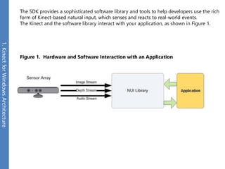
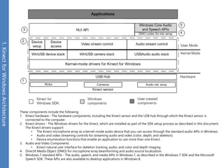
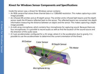
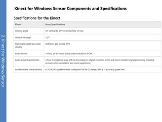
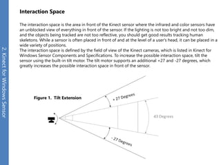
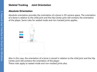
2. 1.Kinect for Windows Architecture
2.Kinect for Windows Sensor
3.Natural User Interface for Kinect for Windows
4.KinectInteraction
5.Kinect Fusion
6.Kinect Studio
7.Face Tracking
3. The SDK provides a sophisticated software library and tools to help developers use the rich form of Kinect-based natural input, which senses and reacts to real-world events.
The Kinect and the software library interact with your application, as shown in Figure 1.
Figure 1.Hardware and Software Interaction with an Application
1. Kinect for Windows Architecture
4. These components include the following:
1.Kinect hardware -The hardware components, including the Kinect sensor and the USB hub through which the Kinect sensor is connected to the computer.
2.Kinect drivers -The Windows drivers for the Kinect, which are installed as part of the SDK setup process as described in this document. The Kinect drivers support:
•The Kinect microphone array as a kernel-mode audio device that you can access through the standard audio APIs in Windows.
•Audio and video streaming controls for streaming audio and video (color, depth, and skeleton).
•Device enumeration functions that enable an application to use more than one Kinect.
3.Audio and Video Components
•Kinect natural user interface for skeleton tracking, audio, and color and depth imaging
4.DirectX Media Object (DMO) for microphone array beamforming and audio source localization.
5.Windows 7 standard APIs -The audio, speech, and media APIs in Windows 7, as described in the Windows 7 SDK and the Microsoft Speech SDK. These APIs are also available to desktop applications in Windows 8.
1. Kinect for Windows Architecture
5. Kinect for Windows Sensor Components and Specifications
Inside the sensor case, a Kinect for Windows sensor contains:
•An RGB camera that stores three channel data in a 1280x960 resolution. This makes capturing a color image possible.
•An infrared (IR) emitter and an IR depth sensor. The emitter emits infrared light beams and the depth sensor reads the IR beams reflected back to the sensor. The reflected beams are converted into depth information measuring the distance between an object and the sensor. This makes capturing a depth image possible.
•A multi-array microphone, which contains four microphones for capturing sound. Because there are four microphones, it is possible to record audio as well as find the location of the sound source and the direction of the audio wave.
•A 3-axis accelerometer configured for a 2G range, where G is the acceleration due to gravity. It is possible to use the accelerometer to determine the current orientation of the Kinect.
2. Kinect for Windows Sensor
6. Kinect for Windows Sensor Components and Specifications
2. Kinect for Windows Sensor
7. Interaction Space
The interaction space is the area in front of the Kinect sensor where the infrared and color sensors have an unblocked view of everything in front of the sensor. If the lighting is not too bright and not too dim, and the objects being tracked are not too reflective, you should get good results tracking human skeletons. While a sensor is often placed in front of and at the level of a user's head, it can be placed in a wide variety of positions.
The interaction space is defined by the field of view of the Kinect cameras, which is listed in Kinect for Windows Sensor Components and Specifications. To increase the possible interaction space, tilt the sensor using the built-in tilt motor. The tilt motor supports an additional +27 and -27 degrees, which greatly increases the possible interaction space in front of the sensor.
Figure 1.Tilt Extension
2. Kinect for Windows Sensor
8. The Kinect for Windows Sensor contains a 3-axis accelerometer configured for a 2g range, where g is the acceleration due to gravity.
This allows the sensor to report its current orientation with respect to gravity.
Accelerometer data can help detect when the sensor is in an unusual orientation. It can also be used along with the floor plane data calculated by the SDK to provide more accurate 3-D projections in augmented reality scenarios.
The accelerometer has a lower limit of 1 degree accuracy. In addition, the accuracy is slightly temperature sensitive, with up to 3 degrees of drift over the normal operating temperature range. This drift can be positive or negative, but a given sensor willalways exhibit the same drift behavior. It is possible to compensate for this drift by comparing the accelerometer vertical (the y-axisin the accelerometer's coordinate system) and the detected floor plane depth data, if required.
Reading and Understanding Accelerometer Data
The Kinect for Windows SDK provides both native and managed methods for reading the accelerometer data. For native, use INuiSensor.NuiAccelerometerGetCurrentReading. For managed, use KinectSensor.AccelerometerGetCurrentReading. The Kinect SDK does NOT provide a change notification event for the accelerometer.
The accelerometer reading is returned as a 3-D vector pointing in the direction of gravity (the floor on a non-accelerating sensor). This 3-D vector is returned as a Vector4 (x, y, z, w) with the w value always set to 0.0. The coordinate system is centered on the sensor, and is a right-handed coordinate system with the positive z in the direction the sensor is pointing at. The vector is in gravityunits (g), or 9.81m/s^2. The default sensor rotation (horizontal, level placement) is represented by the (x, y, z, w) vector whose valueis(0, -1.0, 0, 0).
Figure 1.The Kinect Accelerometer coordinate system
2. Kinect for Windows Sensor
9. 3. Natural User Interface for Kinect for Windows
Data Streams
Audio Stream
The Kinect sensor includes a four-element, linear microphone array, shown here in purple.
The microphone array captures audio data at a 24-bit resolution, which allows accuracy across a wide dynamic range of voice data, from normal speech at three or more meters to a person yelling.
What Can You Do with Audio?
The sensor (microphone array) enables several user scenarios, such as:
•High-quality audio capture
•Focus on audio coming from a particular direction with beamforming
•Identification of the direction of audio sources
•Improved speech recognition as a result of audio capture and beamforming
•Raw voice data access
10. 3. Natural User Interface for Kinect for Windows
Color Stream
Data Streams
Color image data is available at different resolutions and formats. The format determines whether the color image data streamisencoded as RGB, YUV, or Bayer. You may use only one resolution and one format at a time.
The sensor uses a USB connection that provides a given amount of bandwidth for passing data. Your choice of resolution allowsyou to tune how that bandwidth is used. High-resolution images send more data per frame and update less frequently, while lower- resolution images update more frequently, with some loss in image quality due to compression.
Color data is available in the following formats. Color formats are computed from the same camera data, so all data types representthe same image.
The Bayer formats more closely match the physiology of the human eye by including more green pixels values than blue or red. Formore information about Bayer encoding, see the description of a Bayer filter. The Bayer color image data that the sensor returnsat 1280x960 is compressed and converted to RGB before transmission to the runtime. The runtime then decompresses the data beforeitpasses the data to your application. The use of compression makes it possible to return color data at frame rates as high as 30 fps, but the algorithm that is used leads to some loss of image fidelity.
11. Depth Stream
3. Natural User Interface for Kinect for Windows
Data Streams
Each frame of the depth data stream is made up of pixels that contain the distance (in millimeters) from the camera plane to the nearest object. An application can use depth data to track a person's motion or identify background objects to ignore.
The depth data stream merges two separate types of data:
•Depth data, in millimeters.
•Player segmentation data. Each player segmentation value is an integer indicating the index of a unique player detected in the scene.
The depth data is the distance, in millimeters, to the nearest object at that particular (x, y) coordinate in the depth sensor's field of view. The depth image is available in 3 different resolutions: 640x480 (the default), 320x240, and 80x60 as specified using the DepthImageFormat Enumeration. The range setting, specified using the DepthRange Enumeration, determines the distance from the sensor for which depth values are received.
12. 3. Natural User Interface for Kinect for Windows
Infrared Stream
Infrared (IR) light is electromagnetic radiation with longer wavelengths than those of visible light. As a result, infrared light is used in industrial, scientific, and medical applications to illuminate and track objects without visible light.
The depth sensor generates invisible IR light to determine an object's depth (distance) from the sensor. The primary use for the IR stream is to improve external camera calibration using a test pattern observed from both the RGB and IR camera to more accurately determine how to map coordinates from one camera space to another. You can also use IR data to capture an IR image in darkness as long as you provide your own IR source.
The infrared stream is not really a separate data stream, but a particular configuration of the color camera stream.
Infrared data is available in the following format.
Data Streams
13. 3. Natural User Interface for Kinect for Windows
Getting the Next Frame of Data by Polling or Using Events
Data Streams
Application code gets the latest frame of image data (color or depth) by calling a frame retrieval method and passing a buffer. If the latest frame of data is ready, it is copied into the buffer. If the application code requests a frame of data before the new frame is available, an application can either wait for the next frame or return immediately and try again later. The sensor data streams never provide the same frame of data more than once.
Choose one of two models for getting the next frame of data: the polling model or the event model.
Polling Model
The polling model is the simplest option for reading data frames. First, the application code opens the image stream. It then requests a frame and specifies how long to wait for the next frame of data (between 0 and an infinite number of milliseconds). The request method returns when a new frame of data is ready or when the wait time expires, whichever comes first. Specifying an infinite wait causes the call for frame data to block and to wait as long as necessary for the next frame.
When the request returns successfully, the new frame is ready for processing. If the time-out value is set to zero, the application code can poll for completion of a new frame while it performs other work on the same thread. A C++ application calls NuiImageStreamOpen to open a color or depth stream and omits the optional event. To poll for color and depth frames, a C++ application calls NuiImageStreamGetNextFrame and a C# application calls ColorImageStream.OpenNextFrame.
Event Model
The event model supports the ability to integrate retrieval of a skeleton frame into an application engine with more flexibility and more accuracy.
In this model, C++ code passes an event handle to NuiImageStreamOpen to open a color or depth stream. The event handle should be a manual-reset event handle, created by a call to the Windows CreateEventAPI. When a new frame of color or depth data is ready, the event is signaled. Any thread waiting on the event handle wakes and gets the frame of color or depth data by calling NuiImageStreamGetNextFrame or skeleton data by calling NuiSkeletonGetNextFrame. During this time, the event is reset by the NUI Image Camera API.
C# code uses the event model by hooking a Kinect.KinectSensor.ColorFrameReady, KinectSensor.DepthFrameReady, or KinectSensor.SkeletonFrameReady event to the appropriate color, depth, or skeleton event handler. When a new frame of data is ready, the event is signaled and the handler runs and calls the ColorImageStream.OpenNextFrame, DepthImageStream.OpenNextFrame, or SkeletonStream.OpenNextFrame method to get the frame.
14. 3. Natural User Interface for Kinect for Windows
Coordinate Spaces
Data Streams
A Kinect streams out color, depth, and skeleton data one frame at a time. This section briefly describes the coordinate spaces for each data type and the API support for transforming data from one space to another.
Color Space
Each frame, the color sensor captures a color image of everything visible in the field of view of the color sensor. A frame is made up of pixels. The number of pixels depends on the frame size, which is specified by NUI_IMAGE_RESOLUTION Enumeration. Each pixel contains the red, green, and blue value of a single pixel at a particular (x, y) coordinate in the colorimage.
Depth Space
Each frame, the depth sensor captures a grayscale image of everything visible in the field of view of the depth sensor. A frame is made up of pixels, whose size is once again specified by NUI_IMAGE_RESOLUTION Enumeration. Each pixel contains the Cartesian distance, in millimeters, from the camera plane to the nearest object at that particular (x, y) coordinate, as shown in Figure 1. The (x, y) coordinates of a depth frame do not represent physical units in the room; instead, they represent the location of a pixel in the depth frame.
Figure 1.Depth stream values
When the depth stream has been opened with the NUI_IMAGE_STREAM_FLAG_DISTINCT_OVERFLOW_VALUES flag, there are three values that indicate the depth could not be reliably measured at a location. The "too near" value means an object was detected, but it is too near to the sensor to provide a reliable distance measurement. The "too far" value means an object was detected, but too far to reliably measure. The "unknown" value means no object was detected. In C++, when the NUI_IMAGE_STREAM_FLAG_DISTINCT_OVERFLOW_DEPTH_VALUES flag is not specified, all of the overflow values are reported as a depth value of "0".
15. 3. Natural User Interface for Kinect for Windows
Data Streams
Depth Space Range
Coordinate Spaces
The depth sensor has two depth ranges: the default range and the near range (shown in the DepthRange Enumeration). This image illustrates the sensor depth ranges in meters. The default range is available in both the Kinect for Windows sensor and the Kinect for Xbox 360 sensor; the near range is available only in the Kinect for Windows sensor.
16. 3. Natural User Interface for Kinect for Windows
Data Streams
Coordinate Spaces
Skeleton Space
Each frame, the depth image captured is processed by the Kinect runtime into skeleton data. Skeleton data contains 3D position data for human skeletons for up to two people who are visible in the depth sensor. The position of a skeleton and each of the skeleton joints (if active tracking is enabled) are stored as (x, y, z) coordinates. Unlike depth space, skeleton space coordinates are expressed in meters. The x, y, and z-axes are the body axes of the depth sensor as shown below.
Figure 2.Skeleton space
This is a right-handed coordinate system that places a Kinect at the origin with the positive z-axis extending in the direction in which the Kinect is pointed. The positive y-axis extends upward, and the positive x-axis extends to the left. Placing a Kinect on a surface that is not level (or tilting the sensor) to optimize the sensor's field of view can generate skeletons that appear to lean instead of be standing upright.
17. Each skeleton frame also contains a floor-clipping-plane vector, which contains the coefficients of an estimated floor-plane equation. The skeleton tracking system updates this estimate for each frame and uses it as a clipping plane for removing the background and segmenting players. The general plane equation is:
Ax + By + Cz + D = 0
where:
A = vFloorClipPlane.x
B = vFloorClipPlane.y
C = vFloorClipPlane.z
D = vFloorClipPlane.w
The equation is normalized so that the physical interpretation of D is the height of the camera from the floor, in meters. Note that the floor might not always be visible or detectable. In this case, the floor clipping plane is a zero vector.
The floor clipping plane is used in the vFloorClipPlanemember of the NUI_SKELETON_FRAME structure (for C++) and in the FloorClipPlane property in managed code.
Skeletal Mirroring
By default, the skeleton system mirrors the user who is being tracked. That is, a person facing the sensor is considered to be looking in the -z direction in skeleton space. This accommodates an application that uses an avatar to represent the user since the avatar will be shown facing into the screen. However, if the avatar faces the user, mirroring would present the avatar as backwards. If needed, use a transformation matrix to flip the z-coordinates of the skeleton positions to orient the skeleton as necessary for your application.
3. Natural User Interface for Kinect for Windows
Floor Determination
Data Streams
Coordinate Spaces
18. 3. Natural User Interface for Kinect for Windows
Skeletal Tracking
Overview
Skeletal Tracking allows Kinect to recognize people and follow their actions.
Using the infrared (IR) camera, Kinect can recognize up to six users in the field of view of the sensor. Of these, up to two users can be tracked in detail. An application can locate the joints of the tracked users in space and track their movements over time.
Figure 1.Kinect can recognize six people and track two
19. Skeletal Tracking is optimized to recognize users standing or sitting, and facing the Kinect; sideways poses provide some challenges regarding the part of the user that is not visible to the sensor.
To be recognized, users simply need to be in front of the sensor, making sure the sensor can see their head and upper body; no specific pose or calibration action needs to be taken for a user to be tracked.
Figure 2.Skeleton tracking is designed to recognize users facing the sensor
3. Natural User Interface for Kinect for Windows
Skeletal Tracking
20. 3. Natural User Interface for Kinect for Windows
Skeletal Tracking
Field of View
Kinect field of view of the users is determined by the settings of the IR camera, which are set with the DepthRange Enumeration.
In default range mode, Kinect can see people standing between 0.8 meters (2.6 feet) and 4.0 meters (13.1 feet) away; users will have to be able to use their arms at that distance, suggesting a practical range of 1.2 to 3.5 meters. For more details, see the k4w_hig_main.
Figure 3.Kinect horizontal Field of View in default range
21. Figure 4.Kinect vertical Field of View in default range
3. Natural User Interface for Kinect for Windows
Skeletal Tracking
Field of View
In near range mode, Kinect can see people standing between 0.4 meters (1.3 feet) and 3.0 meters (9.8 feet); it has a practical range of 0.8 to 2.5 meters. For more details, see Tracking Skeletons in Near Depth Range.
22. 3. Natural User Interface for Kinect for Windows
Skeletal Tracking
Tracking Users with Kinect Skeletal Tracking
Skeleton Position and Tracking State
The skeletons in a frame have can have a tracking state of "tracked" or "position only". A tracked skeleton provides detailed information about the position in the camera's field of view of twenty joints of the user's body.
A skeleton with a tracking state of "position only" has information about the position of the user, but no details about the joints. An application can decide which skeletons to track, using the tracking ID as shown in the Active User Tracking section.
Tracked skeleton information can also be retrieved in the depth map as shown in the PlayerID in depth map section.
23. 3. Natural User Interface for Kinect for Windows
Skeletal Tracking
Tracking Modes (Seated and Default)
Skeleton tracking a new modality, call seated mode for tracking user skeletons.
The seated tracking mode is designed to track people who are seated on a chair or couch, or whose lower body is not entirely visible to the sensor. The default tracking mode, in contrast, is optimized to recognize and track people who are standing and fully visible to the sensor.
24. 3. Natural User Interface for Kinect for Windows
Skeletal Tracking
Joint Orientation
Bones Hierarchy
We define a hierarchy of bones using the joints defined by the skeletal tracking system.
The hierarchy has the Hip Center joint as the root and extends to the feet, head, and hands:
Figure 1.Joint Hierarchy
Bones are specified by the parent and child joints that enclose the bone. For example, the Hip Left bone is enclosed by the Hip Center joint (parent) and the Hip Left joint (child).
25. 3. Natural User Interface for Kinect for Windows
Skeletal Tracking
Joint Orientation
Bone hierarchy refers to the ordering of the bones defined by the surrounding joints; bones are not explicitly defined as structures in the APIs. Bone rotation is stored in a bone’s child joint. For example, the rotation of the left hip bone is stored in the Hip Left joint.
26. 3. Natural User Interface for Kinect for Windows
Skeletal Tracking
Joint Orientation
Hierarchical Rotation
Hierarchical rotation provides the amount of rotation in 3D space from the parent bone to the child. This information tells us how much we need to rotate in 3D space the direction of the bone relative to the parent.
This is equivalent to considering the rotation of the reference Cartesian axis in the parent- bone object space to the child-bone object space, considering that the bone lies on the y- axis of its object space.
Figure 2.Hierarchical Bone Rotation
27. 3. Natural User Interface for Kinect for Windows
Skeletal Tracking
Joint Orientation
Absolute Player Orientation
In the hierarchical definition, the rotation of the Hip Center joint provides the absolute orientation of the player in camera space coordinates. This assumes that the player object space has the origin at the Hip Center joint, the y-axis is upright, the x-axis is to the left, and the z-axis faces the camera.
Figure 3.Absolute Player Orientation is rooted at the Hip Center joint
To calculate the absolute orientation of each bone, multiply the rotation matrix of the bone by the rotation matrices of the parents (up to the root joint).
28. 3. Natural User Interface for Kinect for Windows
Skeletal Tracking
Joint Orientation
Absolute Orientation
Absolute orientation provides the orientation of a bone in 3D camera space. The orientation of a bone is relative to the child joint and the Hip Center joint still contains the orientation of the player. Same rules for seated mode and non-tracked joints applies.
Also in this case, the orientation of a bone is stored in relation to the child joint and the Hip Center joint still contains the orientation of the player.
These rules apply to seated mode and non-tracked joints also.
29. Speech
3. Natural User Interface for Kinect for Windows
Speech recognition is one of the key functionalities of the NUI API. The Kinect sensor’s microphone array is an excellent input device for speech recognition-based applications. It provides better sound quality than a comparable single microphone and is much more convenient to use than a headset. Managed applications can use the Kinect microphone with the Microsoft.Speech API, which supports the latest acoustical algorithms. Kinect for Windows SDK includes a custom acoustical model that is optimized for the Kinect's microphone array.
Supported Languages for Speech Recognition
Acoustic models have been created to allow speech recognition in several locales in addition to the default locale of en-US. These are runtime components that are packaged individually and are available here. The following locales are now supported:
•de-DE
•en-AU
•en-CA
•en-GB
•en-IE
•en-NZ
•es-ES
•es-MX
•fr-CA
•fr-FR
•it-IT
•ja-JP
30. Kinect for Windows Human Interface Guidelines v1.7.0
3. Natural User Interface for Kinect for Windows
Welcome to the world of Microsoft Kinect for Windows applications. The Human Interface Guidelines (HIG) document is your roadmap to building exciting human-computer interaction solutions you once thought were impossible.
We want to help make your experience with Microsoft Kinect for Windows, and your users’ experiences, the best. So, we’re going to set you off on a path toward success by sharing our most effective design tips and steering you away from any pitfalls we had to negotiate. You’ll be able to focus on all those unique challenges you want to tackle.
Keep this guide at hand –because, as we regularly update it to reflect both our ongoing findings and the evolving capabilities of Kinect for Windows, you’ll stay on the cutting edge.
31. 4. KinectInteraction
KinectInteraction is a term referring to the set of features that allow Kinect-enabled applications to incorporate gesture-based interactivity. KinectInteraction is NOT a part of the stand-alone Kinect for Windows SDK 1.7, but is available through the associated Kinect for Windows Toolkit 1.7.
KinectInteraction provides the following high-level features:
•Identification of up to 2 users and identification and tracking of their primary interaction hand.
•Detection services for user's hand location and state.
•Grip and grip release detection.
•Press detection.
•Information on the control targeted by the user.
The Toolkit contains both native and managed APIs and services for these features. The Toolkit also contains a set of C#/WPF-interaction-enabled controls exposing these features, which enable easy incorporation of KinectInteraction features into graphical applications.
32. KinectInteraction Architecture
4. KinectInteraction
The KinectInteraction features use a combination of the depth stream, the skeletal stream, sophisticated algorithms to provide hand tracking and gesture recognition, and other features. The features are exposed as follows:
The concepts underlying the KinectInteraction features are detailed in KinectInteraction Concepts.
The native API is discussed in KinectInteraction Native API. It provides the underlying features of user identification, handtracking, hand state (tracked, interactive, and so forth), and press targeting. This API also provides a new data stream called the interaction streamthat bubbles up gesture recognition events.
The managed API is discussed in KinectInteraction Managed API. This is a C# API that exposes the same functionality as the nativeAPI.
The C#/WPF controls are discussed in KinectInteraction Controls. These provide WPF controls that can be used to construct interactive applications. The controls include interactive regions, grip-scrollable lists, and interactive button controls that respond to auser's push.
33. 4. KinectInteraction
KinectInteraction Concepts
There are many concepts in the new KinectInteraction features that you may be encountering for the first time. It is important to get a good understanding of these concepts to understand what can and cannot be done with the new features.
The KinectInteraction Controls have been designed to be compatible with keyboard and mouse control of a Kinect-enabled application as well.
Hand Tracking
The Physical Interaction Zone (PhIZ)
What Gets Tracked?
Hand State
Tracked vs. Interactive
The User Viewer
The Hand Pointer
The Hand Pointer and Other Controls
Interaction Types
Grip and Release
Press
Scroll
The Interaction Stream
34. 5. Kinect Fusion
What is Kinect Fusion?
Figure 1: Kinect Fusion in action, taking the depth image from the inect camera with lots of missing data and within a few seconds producing a realistic smooth 3D reconstruction of a static scene by moving the Kinect sensor around. From this, a point cloud or a 3D mesh can be produced.
KinectFusion provides 3D object scanning and model creation using a Kinect for Windows sensor. The user can paint a scene with the Kinect camera and simultaneously see, and interact with, a detailed 3D model of the scene. Kinect Fusion can be run at interactive rates on supported GPUs, and can run at non-interactive rates on a variety of hardware. Running at non-interactive rates may allow larger volume reconstructions.
35. 6. Kinect Studio
Kinect Studio is a tool that helps you record and play back depth and color streams from a Kinect. Use the tool to read and write data streams to help debug functionality, create repeatable scenarios for testing, and analyze performance.
36. 7. Face Tracking
The Microsoft Face Tracking Software Development Kit for Kinect for Windows (Face Tracking SDK), together with the Kinect for Windows Software Development Kit (Kinect For Windows SDK), enables you to create applications that can track human faces in real time.
The Face Tracking SDK’s face tracking engine analyzes input from a Kinect camera, deduces the head pose and facial expressions, and makes that information available to an application in real time. For example, this information can be used to render a tracked person’s head position and facial expression on an avatar in a game or a communication application or to drive a natural user interface (NUI).
This version of the Face Tracking SDK was designed to work with Kinect sensor so the Kinect for Windows SDK must be installed before use.
37. 7. Face Tracking
Face Tracking Outputs
This section provides details on the output of the Face Tracking engine. Each time you call StartTrackingor ContinueTracking, FTResultwill be updated, which contains the following information about a tracked user:
•Tracking status
•2D points
•3D head pose
•AUs
2D Mesh and Points
The Face Tracking SDK tracks the 87 2D points indicated in the following image (in addition to 13 points that aren’t shown in Figure 2 -Tracked Points):
Figure 2.Tracked Points
These points are returned in an array, and are defined in the coordinate space of the RGB image (in 640 x 480 resolution) returned from the Kinect sensor.
The additional 13 points (which are not shown in the figure) include:
•The center of the eye, the corners of the mouth, and the center of the nose
•A bounding="" box around the head
38. 7. Face Tracking
3D Head Pose
The X,Y, and Z position of the user’s head are reported based on a right-handed coordinate system (with the origin at the sensor, Z pointed towards the user and Y pointed UP –this is the same as the Kinect’s skeleton coordinate frame). Translations are in meters.
The user’s head pose is captured by three angles: pitch, roll, and yaw.
Figure 3.Head Pose Angles