Hardware realization of Stereo camera and associated embedded system

Stereo camera has two lenses about the same distance apart as human eyes with a separate image sensor for each lenses. This allows the camera to simulate human binocular vision, and therefore gives it ability to capture three dimensional images. It detects depth information of the subject which allows user to capture image that are instantly rendered in 3D. Stereo cameras are also required in stereo vision, a ranging method which finds its application in almost every field. Still stereo 3D hasn’t yet become a standard because of technical problems, including agronomy issues, cost, and lack of hardware and software standards. Due to above reasons, it is important to achieve the low cost and standard hardware for 3D vision for which a novel architecture of a stereo camera is required. This paper proposes to provide low cost solution to stereo cameras as cameras can be designed as per requirement and mainly focuses on the processing of sensor raw image data.

Recommended
Recommended
More Related Content
What's hot
What's hot (18)
Viewers also liked
Viewers also liked (19)
Similar to Hardware realization of Stereo camera and associated embedded system
Similar to Hardware realization of Stereo camera and associated embedded system (20)
Recently uploaded
Recently uploaded (20)
Hardware realization of Stereo camera and associated embedded system
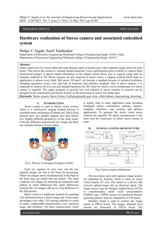
- 1. Shilpa V. Ingale et al. Int. Journal of Engineering Research and Applications www.ijera.com ISSN : 2248-9622, Vol. 5, Issue 5, ( Part -5) May 2015, pp.56-60 www.ijera.com 56 | P a g e Hardware realization of Stereo camera and associated embedded system Shilpa V. Ingale, Sunil Tamhankar Department of Electronics Engineering Walchand College of Engineering Sangli, 416415, India Department of Electronics Engineering Walchand college of Engineering Sangli, 416415 Abstract Stereo camera has two lenses about the same distance apart as human eyes with a separate image sensor for each lenses. This allows the camera to simulate human binocular vision, and therefore gives it ability to capture three dimensional images. It detects depth information of the subject which allows user to capture image that are instantly rendered in 3D. Stereo cameras are also required in stereo vision, a ranging method which finds its application in almost every field. Still stereo 3D hasn’t yet become a standard because of technical problems, including agronomy issues, cost, and lack of hardware and software standards. Due to above reasons, it is important to achieve the low cost and standard hardware for 3D vision for which a novel architecture of a stereo camera is required. This paper proposes to provide low cost solution to stereo cameras as cameras can be designed as per requirement and mainly focuses on the processing of sensor raw image data. Keywords- Stereo camera, Stereo Vision, Field programable gate array, white balance, demosaicing, denoising. I. INTRODUCTION Stereo camera is used in Stereo vision system, which is a well-known ranging method because it resembles basic mechanism of human eye. Most of the animals have two parallel aligned eyes that deliver two slightly different perspective of the same scene. From the difference between the two images the brain can calculate distance of each object. Fig 1 .Process of merging of images in brain Each eye captures its own view and the two separate images are sent to the brain for processing. When two images arrive simultaneously in the back of the brain they are united into one picture. The mind combines two images by matching up similarities and adding in small differences.The small differences between the two images add up to a big difference in the final picture. Stereo vision is a traditional method for acquiring 3-D information from a stereo image pair. It has many advantages over other 3-D sensing methods in terms of safety, undetectable characteristics, cost, operating range, and reliability. For these reasons,stereo vision is widely used in many application areas including intelligent robots, autonomous vehicles, human– computer interfaces, and security and defence applications. To generate the stereo vision stereo cameras are required. 3D object reconstruction is the main area for researchers in which stereo camera is used. II. OVERALL SYSTEM ARCHITECTURE Fig 2 stereo camera architecture The two lenses each with separate image sensors are separated by distance which is same as stereo vision (nearly 6.5 cm). The sensor is a device that converts optical image into an electrical signal. The image sensors may be charged coupled device (CCD) or complementary metal oxide semiconductor (CMOS) type. CMOS sensors are preferred because operating speed is more as compared to CCD sensor. Interface board is used to connect the image sensor to FPGA board. The images obtained from sensors are processed on FPGA board. The RESEARCH ARTICLE OPEN ACCESS
- 2. Shilpa V. Ingale et al. Int. Journal of Engineering Research and Applications www.ijera.com ISSN : 2248-9622, Vol. 5, Issue 5, ( Part -5) May 2015, pp.56-60 www.ijera.com 57 | P a g e processing of raw sensor data and entire stereo vision process like stereo correspondence, stereo rectification, post processing is realized using FPGA board. The processed images are then passed to host computer running Linux through PCIe interface. III. PROCESSING OF RAW SENSOR DATA The image obtained from sensor is raw image and is not directly in viewable form. RAW image is an uncompressed image containing the sensor pixel values as well as a large amount of meta-information about the image generated by the camera. RAW images come in many formats and at least one common open format, .DNG, which stands for Digital Negative. In order to display the image on a screen, the raw image has to undergo three important process white balance, demosaicing, color transfer, and to non- linearly compressed its pixel value to yield the image information. When working with raw sensor data images it is important to account for each of these steps in order to display your results correctly. Fig 3. Image processing pipeline of a single lens camera A. Nature of Raw Sensor Data Raw data from an image sensor contains information about a scene, but it is not intrinsically recognizable to the human eye. It is a single channel intensity image, possibly with a non-zero minimum value to represent black, with integer values that contain 10-14 bits of data. In order to get a full color image, most sensors use filtering to look at the light in its three primary colors. Once the camera records all three colors, it combines them to create the full spectrum. There are several ways of recording the three colors in a digital camera. The highest quality cameras use three separate sensors, each with a different filter. But the cameras that use this method tend to be bulky and expensive. Another method is to rotate a series of red, blue and green filters in front of a single sensor. But for this method, both the camera and the target of the photo must remain stationary for all three readings. A more economical and practical way to record the primary colors is to permanently place a filter called a color filter array over each individual photo- site. By breaking up the sensor into a variety of red, blue and green pixels, it is possible to get enough information in the general vicinity of each sensor to make very accurate guesses about the true color at that location. This process is called interpolation. The most common pattern of filters is the Bayer filterpattern. This pattern alternates a row of red and green filters with a row of blue and green filters. The pixels are not evenly divided. There are as many green pixels as there are blue and red combined. This is because the human eye is not equally sensitive to all three colors. Fig 4. Bayer filter pattern The advantages of this method are that only one sensor is required, and all the color information(red, green and blue) is recorded at the same moment. That means the camera can be smaller, cheaper, and useful in awider variety of situations. The raw output from a sensor with a Bayer filter is a mosaic of red, green and blue pixels of different intensities. B. Demosaicing Raw sensor data typically comes in the form of a Color Filter Array (CFA). This is an m-by-n array of pixels where each pixel carries information about a single color channel: red, green, or blue. Since light falling on any given photosensor in the CCD is recorded as some number of electrons in a capacitor, it can only be saved as a scalar value; a single pixel cannot retain the 3-dimensional nature of observable light. To find the true color value at any pixel location, the other two color values are interpolated from nearby neighbors where those colors are known. This process is called demosaicing, and produces the m-by-n-by-3 array of RGB values at each pixel location we typically expect from a color digital image. The aim of a demosaicing algorithm is to reconstruct a full color image from the spatially under-sampled color channels output from the CFA. The algorithm should have the following traits: Avoidance of the introduction of false color artifacts, such as chromatic aliases, zippering (abrupt unnatural changes of intensity over a number of neighboring pixels) and purple fringing. Maximum preservation of the image resolution. Low computational complexity for fast processing or efficient in-camera hardware implementation.
- 3. Shilpa V. Ingale et al. Int. Journal of Engineering Research and Applications www.ijera.com ISSN : 2248-9622, Vol. 5, Issue 5, ( Part -5) May 2015, pp.56-60 www.ijera.com 58 | P a g e Amenability to analysis for accurate noise reduction. Different algorithms for demosaicing a) Single-channel interpolation:These algorithms, such as bilinear/bicubic interpolation and spline interpolation, estimate missing color values for each of the three color planes separately. They can be easily implemented, but they totally ignore the inter- channel correlation that can be used to improve the demosaicing performance, for instance, reducing color fringes at sharp edges. As a result, these costeffective methods usually introduce demosaicing artifacts such as blurring and false colors. (b) Inter-channel interpolation:These methods exploit the inter-channel dependency and interpolate all color planes to get the missing values .Generally, these algorithms, such as template matching, detect edges in the CFA image first, then average the pixels along the edges rather than across them. They tend to have better performance but their performance varies with the content of image and can have large computational complexity. (c) Frequency selection interpolation:These methods exploit the characteristics of CFA image, and isolate the luminance and chrominance in spatial frequency domain by means of filtering. In this method, the performance highly depends on the design of filters used to select spectral components and the content of input image. As a result, incorporating adaptive filtering can significantly improve the performance of the algorithm. General procedure of demosaicing based on frequency selection method. Use low pass filter to get estimated luminance lum from CFA image Use high pass filter or orthogonal filter of low pass filter in above step to get the chrominance chr. Get demultiplexed chr, i.e., chrd. Use simple interpolation methods, such as bilinear demosaicing algorithm, to get estimated chrominance chre. Use lum and chre to get reconstructed full-color image: Id= lum + chre C. White balance: White balance is an important function of digital cameras. The goal of white balance is to adjust the image such that it looks as if it is taken under canonical light. When an image of a scene is captured by a digital camera, the sensor response at each pixel depends on the illumination. That is, each pixel value recorded by the sensor is related to the color temperature of the light source. When a white object is illuminated under a low color temperature, it will appear reddish in the recorded image. Similarly, it will appear bluish under a high color temperature. The goal of white balance is to process the image such that it looks as if it is taken under canonical light. Generally, white balance algorithms consist of two steps. It first estimate the illumination, and then use the result obtained to compensate the image. IV. IMAGE DENOISING Data sets collected by image sensors are generally contaminated by noise. Imperfect instruments, problems with the data acquisition process, and interfering natural phenomena can all degrade the data of interest. Furthermore, noise can be introduced by transmission errors and compression. Thus, denoising is often a necessary and the first step to be taken before the images data is analyzed. It is necessary to apply an efficient denoising technique to compensate for such data corruption. Noise removal introduces artifacts and causes blurring of the images. So it is necessary to choose proper denoising method. Noise modeling in images is greatly affected by capturing instruments, data transmission media, image quantization and discrete sources of radiation. Different algorithms are used depending on the noise model. Most of the natural images are assumed to have additive random noise which is modeled as a Gaussian. A. Denoising algorithm using wavelet transform An image is often corrupted by noise in its acquisition and transmission. Image denoising is used to remove the additive noise while retaining as much as possible the important signal features. Wavelet provides an appropriate basis for separating noisy signal from the image signal. The motivation is that as the wavelet transform is good at energy compaction, the small coefficient are more likely due to noise and large coefficient due to important signal features. These small coefficients can be thresholded without affecting the significant features of the image. a) Wavelet transform Consider a real or complex value continuous time function ψ (t) with following properties: 1. The function integrates to zero 0)( dtt (1) 2. It is square integrable or equivalently has finite energy: dt2|^| (2) The function ψ (t) is a mother wavelet or wavelet if it satisfies this properties as well as admissibility condition.
- 4. Shilpa V. Ingale et al. Int. Journal of Engineering Research and Applications www.ijera.com ISSN : 2248-9622, Vol. 5, Issue 5, ( Part -5) May 2015, pp.56-60 www.ijera.com 59 | P a g e Let (t) be any square integrable function. The CWT or continuous wavelet transform of (t) with respect to a wavelet ψ (t) is defined as: dt a bt a tfbaW || 1 )(),( a bt a tba * || 1 )(, Therefore equation 1 can be written as )(,)(),( tbatfbaW Where, a- Scale or dilation variable which determines amount of time scaling or dilation and a≠0 b- Time shift or translation Asterisk *denotes complex conjugate 1/√a – normalizing factor – ensures that energy stays same for all a and b (transformed signal will have the same energy at every scale) i.e dttdttba 2|^)(|2^)(, Both (t) and ψ (t) belongs to L²(R), set of square integrable functions, and also called as set of energy signals. The analysis function ψ (t), the so-called mother wavelet, is scaled by a, so a wavelet analysis is often called a time-scale analysis rather than a time- frequency analysis. The wavelet transform decomposes the signal into different scales with different levels of resolution by dilating a single prototype function, the mother wavelet. b) Discrete wavelet transform: Fig 11. Discrete wavelet transform Thresholding is a simple non-linear technique, which operates on one wavelet coefficient at a time. In its most basic form, each coefficient is thresholded by comparing against threshold, if the coefficient is smaller than threshold, set to zero; otherwise it is kept or modified. Replacing the small noisy coefficients by zero and inverse wavelet transform on the result may lead to reconstruction with the essential signal characteristics and with less noise. Steps in Image Denoising using wavelet thresholding is as follows: • Apply wavelet transform to the noisy signal to produce the noisy wavelet coefficients. • Select appropriate threshold limit at each level and threshold method to best remove the noises. • Inverse wavelet transform of the thresholded wavelet coefficients to obtain a denoised signal. V. CONCLUSION In this paper, hardware realization of stereo camera and associated embedded system is studied and processing on sensor raw data is implemented. Large number of stereo cameras are required for 3D reconstruction of object from its 2D view. Stereo cameras have been shown to be helpful in removing the ambiguities in the process and also preserve the scale. As the camera can be designed as per requirement, low cost solution is provided. Also the FPGA board used provides various advantages like parallel processing, pipelining, ensures entire stereo vision process to be realized in real time. REFERENCES [1] FPGA Design and Implementation of a Real-Time Stereo Vision System IEEE transactions on circuits and systems for video technology, vol. 20, no. 1, january 2010. [2] Adaptive Wavelet Thresholding for Image Denoising and Compression S. Grace Chang, Student Member, IEEE, Bin Yu, Senior Member, IEEE, and Martin Vetterli, Fellow, ieee transactions on image processing, vol. 9, no. 9, september 2000. [3] Adaptive Homogeneity-Directed Demosaicing Algorithm Keigo Hirakawa, Student Member, IEEE and Thomas W. Parks, Fellow, IEEE. IEEE TRANSACTIONS ON IMAGE PROCESSING, VOL. 14, NO. 3, MARCH 2005
- 5. Shilpa V. Ingale et al. Int. Journal of Engineering Research and Applications www.ijera.com ISSN : 2248-9622, Vol. 5, Issue 5, ( Part -5) May 2015, pp.56-60 www.ijera.com 60 | P a g e [4] Xiang Zhang and Zhangwei Chen “SAD- Based Stereo Vision Machine on a System- on-Programmable-Chip (SoPC)” IEEE journal on sensors, 4 march 2013. [5] Processing raw images in matlab, Rob sumner, Department of electrical engineering, UC Santa Cruz, May 19, 2014 [6] Digital camera image formation: processing and storage, Aaron Deever, Mrityunjay Kumar and Bruce Pillman [7] A rewiew of frequency selection algorithm of image demosicing by Shaung Liu. [8] A novel automatic white balance method for digital still cameras by Ching-Chih Weng, Homer Chen.