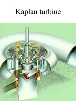
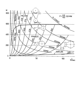
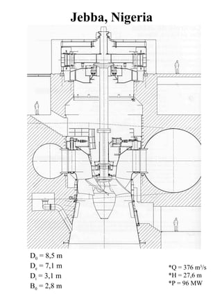
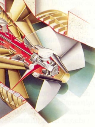
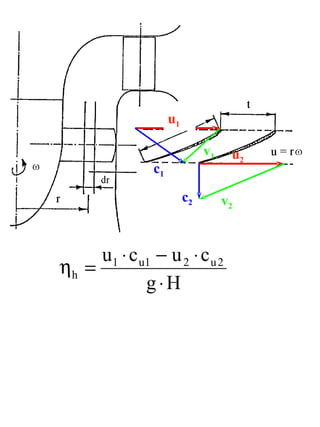
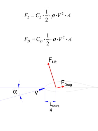
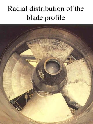
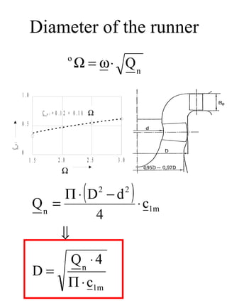
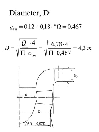
Kaplan turbine
Jebba, Nigeria


D0 = 8,5 m
De = 7,1 m                    *Q = 376 m3/s
Di = 3,1 m                    *H = 27,6 m
B0 = 2,8 m                    *P = 96 MW
Machicura, CHILE


               *Q = 144 m3/s
               *H = 36,7 m
               *P = 48 MW


                   D0 = 7,2 m
                   De = 4,2 m
                   Di = 1,9 m
                   B0 = 1,3 m
Outlet       Outlet   Inlet    Outlet     Inlet
draft tube   runner   runner   guide vane guide vane
Hydraulic efficiency
Hydraulic efficiency ηh


                                              Runner blade angle
                                              φ = constant


                                Flow rate Q
Hill chart
u1

                               v1    u2
                c1

                          c2        v2


     u 1 ⋅ c u1 − u 2 ⋅ c u 2
ηh =
              g⋅H
Pressure distribution and
         torque

c


                   Lift


                          Drag


               L
      Torque

                    D


         Arm
1
    FL = C L ⋅ ⋅ ρ ⋅ V ⋅ A
                      2

              2

              1
    FD = C D ⋅ ⋅ ρ ⋅ V ⋅ A
                      2

              2

               FLift


                         FDrag
α       v
                LChord
                4
Blade profile data
CD
CL


                      Angle of attack

Angle of attack
   δ
           vv
   Average relative
       velocity
Pressure distribution and
           torque

            0,24 · l          Cord length, l

                                      Suction side


                                      Pressure side

                          Single profile
           Cascade

The pressure at the outlet is lower for a cascade than
for a single profile. The cavitation performance will
therefore be reduced in a cascade.
Radial distribution of the
        blade profile


                       CL =Lift coefficient for a cascade

                       CL1 =Lift coefficient for a single profile


The ratio t/l influences the lift coefficient in a
cascade. The cord length for a blade will therefore
increase when the radius becomes increase
Radial distribution of the
      blade profile
Flow in the axial plane


The figure shows blades with two different design
of the blade in radial direction. This is because it
will influence the secondary flow in the radial
direction
Main dimension of a
  Kaplan turbine
Diameter of the runner
                                        o
                                            Ω = ω ⋅ Qn

      1 .0

                    C   m l   = 0 . 1 2 + 0 .1 8 0 Ω (tiln æ rm   e t)

      0 .5
m l
C


      0
             1 .5                2 .0               2 .5                 3 .0
                                   0
                                       Ω


              Qn =
                   Π⋅ D −d
                           ⋅ c1m
                                                (          2                    2
                                                                                    )
                       4
                   ⇓
                                           Qn ⋅ 4
              D=
                                        Π ⋅ c1m
Height of the guide vanes
       and runner diameter
                                                                                     P
                0 .7
                                                                     ns = n ⋅        54
                0 .6
                                                                                 H   n
                                                      d /D
d /D , B 0/D


               0 .5
                                   B 0/D
               0 .4


                0 .3
                       300   400           500               600   700   800   900
                                                 ns
Gap between hub and ring
    and the runner blades

Gap between the
blade and ring


Gap between the
blade and hub


                                 0 .9 0
          V Efficiencyd


                                                             s = x 1 0 -3 d
            ir k n in g s g ra


                                 0 .8 5


                                 0 .8 0
                                          0   1          2          3          4     5   6
                                              S p a l t e å pGap x = 1 0 0 0 s / D
                                                             n in g
Runaway speed
                                  2 .6
RRunaway/ nspeedu r t a l l


                                                                                ϕ2       ϕ1
                                  2 .4
  u s n in g s ta ll o r m a lt


                                                                          ϕ3
                                                                     ϕ4
                                  2 .2
                                                               ϕ5

                                                          ϕ6
                                  2
                                                                                                     V o it h

                                         0   0 .5      1 .0                    2 .0           3 .0
                                               Cavitation scoefficient t σ
                                                     k a v ita jo n s k o e ff is ie n


                                                        10 − H S
                                                     σ=
                                                           H
                    The figure shows different runaway speed at
                    different runner blade openings. The runaway speed
                    is dependent of the cavitation as shown in the figure
Hill chart
Example
• Find the dimensions D, d and Bo

• Given data:    P = 16,8 MW
                 H = 16 m
                 Qn = 120 m3/s
                 n = 125 rpm
Speed number:
      2 ⋅ g ⋅ H = 2 ⋅ 9,82 ⋅16 = 17,7 m s

       n ⋅ 2 ⋅ Π 125 ⋅ 2 ⋅ Π
    ω=          =            = 13,1 rad
          60        60                  s

           ω        13,1 rad
    ω=             =        s = 0,74 m −1
         2 ⋅ g ⋅ H 17,7 m
                           s
                      120 m3
             Q               s = 6,78 m 2
    Qn =            =
          2 ⋅ g ⋅ H 17,7 m
                             s


o
    Ω = ω ⋅ Q n = 0,74 ⋅ 6,78 = 1,93
Diameter, D:
 c1m = 0,12 + 0,18 ⋅ o Ω = 0,467

     Qn ⋅ 4       6,78 ⋅ 4
D=             =           = 4,3 m
     Π ⋅ c1m     Π ⋅ 0,467
Diameter, d:
                               P                 22826 Hp
ns = n ⋅                              = 125rpm ⋅          = 590
                             Hn 4
                              5
                                                  16m 54


                0 .7


                0 .6
                                                            d /D
d /D , B 0/D


               0 .5
                                      B 0/D
               0 .4


                0 .3
                       300      400           500                  600   700   800   900
                                                    n   s


               d
                 = 0,45 ⇒ d = D ⋅ 0,45 = 1,9 m
               D
Height, B:
                0 .7


                0 .6
                                                         d /D
d /D , B 0/D


               0 .5
                                   B 0/D
               0 .4


                0 .3
                       300   400           500                  600   700   800   900
                                                 n   s


BO
   = 0,41 ⇒ BO = D ⋅ 0,41 = 1,76 m
D
Number of vanes, z:


                 l
                   = 0,95   Number of blades z
                 t

                 z=5

Kaplan turbines

  • 1.
  • 3.
    Jebba, Nigeria D0 =8,5 m De = 7,1 m *Q = 376 m3/s Di = 3,1 m *H = 27,6 m B0 = 2,8 m *P = 96 MW
  • 4.
    Machicura, CHILE *Q = 144 m3/s *H = 36,7 m *P = 48 MW D0 = 7,2 m De = 4,2 m Di = 1,9 m B0 = 1,3 m
  • 5.
    Outlet Outlet Inlet Outlet Inlet draft tube runner runner guide vane guide vane
  • 6.
    Hydraulic efficiency Hydraulic efficiencyηh Runner blade angle φ = constant Flow rate Q
  • 8.
  • 9.
    u1 v1 u2 c1 c2 v2 u 1 ⋅ c u1 − u 2 ⋅ c u 2 ηh = g⋅H
  • 10.
    Pressure distribution and torque c Lift Drag L Torque D Arm
  • 11.
    1 FL = C L ⋅ ⋅ ρ ⋅ V ⋅ A 2 2 1 FD = C D ⋅ ⋅ ρ ⋅ V ⋅ A 2 2 FLift FDrag α v LChord 4
  • 12.
    Blade profile data CD CL Angle of attack Angle of attack δ vv Average relative velocity
  • 13.
    Pressure distribution and torque 0,24 · l Cord length, l Suction side Pressure side Single profile Cascade The pressure at the outlet is lower for a cascade than for a single profile. The cavitation performance will therefore be reduced in a cascade.
  • 14.
    Radial distribution ofthe blade profile CL =Lift coefficient for a cascade CL1 =Lift coefficient for a single profile The ratio t/l influences the lift coefficient in a cascade. The cord length for a blade will therefore increase when the radius becomes increase
  • 15.
    Radial distribution ofthe blade profile
  • 16.
    Flow in theaxial plane The figure shows blades with two different design of the blade in radial direction. This is because it will influence the secondary flow in the radial direction
  • 17.
    Main dimension ofa Kaplan turbine
  • 18.
    Diameter of therunner o Ω = ω ⋅ Qn 1 .0 C m l = 0 . 1 2 + 0 .1 8 0 Ω (tiln æ rm e t) 0 .5 m l C 0 1 .5 2 .0 2 .5 3 .0 0 Ω Qn = Π⋅ D −d ⋅ c1m ( 2 2 ) 4 ⇓ Qn ⋅ 4 D= Π ⋅ c1m
  • 19.
    Height of theguide vanes and runner diameter P 0 .7 ns = n ⋅ 54 0 .6 H n d /D d /D , B 0/D 0 .5 B 0/D 0 .4 0 .3 300 400 500 600 700 800 900 ns
  • 20.
    Gap between huband ring and the runner blades Gap between the blade and ring Gap between the blade and hub 0 .9 0 V Efficiencyd s = x 1 0 -3 d ir k n in g s g ra 0 .8 5 0 .8 0 0 1 2 3 4 5 6 S p a l t e å pGap x = 1 0 0 0 s / D n in g
  • 21.
    Runaway speed 2 .6 RRunaway/ nspeedu r t a l l ϕ2 ϕ1 2 .4 u s n in g s ta ll o r m a lt ϕ3 ϕ4 2 .2 ϕ5 ϕ6 2 V o it h 0 0 .5 1 .0 2 .0 3 .0 Cavitation scoefficient t σ k a v ita jo n s k o e ff is ie n 10 − H S σ= H The figure shows different runaway speed at different runner blade openings. The runaway speed is dependent of the cavitation as shown in the figure
  • 22.
  • 23.
    Example • Find thedimensions D, d and Bo • Given data: P = 16,8 MW H = 16 m Qn = 120 m3/s n = 125 rpm
  • 24.
    Speed number: 2 ⋅ g ⋅ H = 2 ⋅ 9,82 ⋅16 = 17,7 m s n ⋅ 2 ⋅ Π 125 ⋅ 2 ⋅ Π ω= = = 13,1 rad 60 60 s ω 13,1 rad ω= = s = 0,74 m −1 2 ⋅ g ⋅ H 17,7 m s 120 m3 Q s = 6,78 m 2 Qn = = 2 ⋅ g ⋅ H 17,7 m s o Ω = ω ⋅ Q n = 0,74 ⋅ 6,78 = 1,93
  • 25.
    Diameter, D: c1m= 0,12 + 0,18 ⋅ o Ω = 0,467 Qn ⋅ 4 6,78 ⋅ 4 D= = = 4,3 m Π ⋅ c1m Π ⋅ 0,467
  • 26.
    Diameter, d: P 22826 Hp ns = n ⋅ = 125rpm ⋅ = 590 Hn 4 5 16m 54 0 .7 0 .6 d /D d /D , B 0/D 0 .5 B 0/D 0 .4 0 .3 300 400 500 600 700 800 900 n s d = 0,45 ⇒ d = D ⋅ 0,45 = 1,9 m D
  • 27.
    Height, B: 0 .7 0 .6 d /D d /D , B 0/D 0 .5 B 0/D 0 .4 0 .3 300 400 500 600 700 800 900 n s BO = 0,41 ⇒ BO = D ⋅ 0,41 = 1,76 m D
  • 28.
    Number of vanes,z: l = 0,95 Number of blades z t z=5