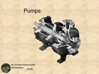
Pumps
Goals
•   Describe how centrifugal and positive-displacement
    pumps operate and common applications.
•   Calculate system head requirements.
•   Determine head, pump efficiency, and pump.
    horsepower from a typical centrifugal pump curve.
•   Define net positive suction head (NPSH) and
    understand how it relates to cavitation.
•   Compute NPSH required by a pump.
•   Determine an appropriate pump (impeller diameter,
    efficiency, etc.) for a given required head.
•   Describe how to modify system to operate on the
    appropriate pump curve.
Background
               Fluid Moving Equipment
Fluids are moved through flow systems using pumps, fans,
blowers, and compressors. Such devices increase the
mechanical energy of the fluid. The additional energy can
be used to increase
• Velocity (flow rate)
• Pressure
• Elevation
Background
Pump, fan, blower, and compressor are terms
that do not have precise meaning. Generally
pumps move liquids while fans, blowers and
compressors add energy to gasses.

Pumps and fans do not appreciably affect the
density of the fluids that they move and thus
incompressible flow theory is applicable.
Centrifugal Pumps
Most common type of pumping machinery. There are many
types, sizes, and designs from various manufacturers who
also publish operating characteristics of each pump in the
form of performance (pump) curves. The device pictured on
the cover page is a centrifugal pump.

Pump curves describe head delivered, pump efficiency, and
net positive suction head (NPSH) for a properly operating
specific model pump.

Centrifugal pumps are generally used where high flow rates
and moderate head increases are required.
Impeller
Positive Displacement Pumps
To move fluids positive displacement pumps admit a
fixed volume of liquid from the inlet into a chamber
and eject it into the discharge.

Positive displacement pumps are used when higher
head increases are required. Generally they do not
increase velocity.
Pump Specification
             Recall Mechanical Energy Balance


 W
       (
  ˆ = ∆ αV
             2
                 ) + g∆z + ∆p + 4 f   L        V
                                         + ∑ Ki 
                                                  2
                                                      N •m
         2                 ρ    
                                      D         2    kg


 Wˆ =  (     +
                 )
      ∆ α V 2 g∆z ∆p 
                  +
                           L        
                     + 4 f + ∑ K i 
                                      V2              ft • lb f
        2 gc   gc   ρ  D            2 gc              lbm

Both equations describe work that must be supplied to system
Pump Head
What happens if the MEB is multiplied through by g (gc/g)?

  ˆ
    = 
            (
 W 1  ∆ αV 2    )
              + g∆z +
                      ∆p     L        V 
                        + 4 f + ∑ K i 
                                          2

                                            
 g g 2               ρ  D             2 

 What are the units (SI)?
 N • m s2    kg • m 3 s 2
         2 =               =m
  kg m       kg • s m
                   2     2


  ^
  W/g has units of length and is known as the pump head
Example

                                 2
                             3
               1
                             Tank B
             Tank A


Why do we choose point 2 rather than 3 for MEB?


What kind of valve to uses to control flow rate?
Example
                                 2
                             3
               1
                             Tank B
             Tank A


Mechanical Energy Balance (in terms of head)
              ∆p          L        V
                                       2
     H = ∆z +    + 1 + 4 f + ∑ K i 
              ρg          D         2g
                    V 2 
        = H min + φ 
                     2g 
                         
                        
Head vs. Flow Rate
                   V 2 
     H = H min + φ 
                    2g 
                        
                       

                                      Quadratic
                                      In V or q
                        2
         L         V
 1 + 4 f D + ∑ K i  2 g
                   

                                           g c ∆p
                            H min = ∆z +
                                                    ρg
System Response
                                  2
                              3
                 1
                              Tank B
               Tank A


What happens when flow control valve is closed?
• Resistance (f) increases
• Flow rate decreases
• Need more head to recover flow rate
System Response
                      Constant
                   Flow Response


Valve Closed              Valve Open


                   Constant
                Head Response
Pump Curves
Pump manufacturers supply performance
curves for each of their pumps. These are
normally referred to as ‘pump curves’. These
curve are generally developed using water as
the reference fluid.
The following can be read directly from a pump
curve:
• Head vs. flow rate information for any fluid
• Pump efficiency for any fluid
• Pump horsepower for system operating with water
Pump Performance Curves
    Efficiency


 Impeller                                                    NPSH
 Diameter


Developed
Head
                                                             Horsepower


                                  Flow Rate
                       http://capsicum.me.utexas.edu/ChE354/resources.html
Power Input
For fluids other than water:
                                Wˆ
                            P=m
                              
                                η
                    ˆ                            m
              
                W                            

              g     ft • lb f  gal  1  ft 3   lbm 
            H      
                    lb        ∗ q
                                min  ∗ 7.48  gal  ∗ ρ  ft 3 
                                                               
              gc                                            
P (hp ) =                 m
                                   ft • lb f      s 
                          η ∗ 550            ∗ 60     
                                    s • hp        min 
Power Input

                    Easier Way

           Pfluid     ρ fluid
                    =         = Sp. Gr. fluid
           Pwater     ρ water


Note: A less dense fluid requires less horsepower
Q = 300 gpm   Example
  Di= 10”
Head(ft) =
η(%) =
P(hp) =

   Di= 10”
Head(ft) =
η(%) =
P(hp) =

   Di= 10”
Head(ft) =
η(%) =
P(hp) =
Goulds Pump Curves
Manufacturers provide series of pumps to cover broad ranges of
capacities, heads, and suction and discharge piping diameters. Most
pumps can be equipped with different diameter impellers and can be
operated at different speeds to change capacities.

The curves provided are for a few variations of the Goulds model 3196
process pump. Each curve corresponds to a specific pump and a
specific RPM. Pump sizes are denoted with 3 numbers.

                             3x4-7

            Discharge           Suction             Casing
            Diameter           Diameter            Diameter
             Inches             Inches              Inches

                               Note: Try to match process piping diameters
                               with the pump discharge and suction diameters.
Pump Selection
Goal is to find a pump whose curve matches the piping
system head vs. flow rate curve. We can superimpose the
previous head-flow rate curve on the manufacturers pump
curves.

To select a specific pump from a product line, find the pump
with the highest efficiency that does not require the use of
the largest impeller diameter. This will allow for future
production expansions.
Suppose that we have a process that requires a flow rate of
300 gpm and has a head requirement of 60 ft. at that flow
rate. Can a 3x4-10 model 3196 Goulds pumps be used?
Example
          Impeller Diameter =


          For Desired Q
             Head =


          How do can you force
          the system to operate
          on the pump curve?
Net Positive Suction Head (NPSH)
Associated with each H-Q location on the pump curve is a
quantity that can be read called NPSH.
An energy balance on the suction side of the fluid system
(point 1 to pump inlet) with pinlet set to the vapor pressure of
the fluid being pumped gives a quantity called NPSHA (net
positive suction head available).

        g c  p1 − pv      L        Vinlet 
                                         2
NPSHA =             −  4 f + ∑ Ki          + ( z1 − zinlet )
        g  ρ              D        2 
Net Positive Suction Head
The requirement is that:

                NPSHA > NPSH
Otherwise (if NPSHA < NPSHpump), the pressure at the
pump inlet will drop to that of the vapor pressure of the
fluid being moved and the fluid will boil.
The resulting gas bubbles will collapse inside the pump as
the pressure rises again. These implosions occur at the
impeller and can lead to pump damage and decreased
efficiency.
                     Cavitation
NPSH
Do not use NPSH to size or select a pump unless all else
fails. Pump selection is governed by H vs. Q requirements
of system. When NPSHA is too small, it might be increased
by:

• Increasing source pressure (not usually feasible)
• Cooling liquid to reduce vapor pressure (not usually
  feasible)
• Raise elevation of source reservoir
• Lower elevation of pump inlet
• Raise level of fluid in reservoir
If NPSHA Can’t Be Increased

If the pump must be modified to achieve proper NPSH:

• Larger slower-speed pump
• Double suction impeller
• Larger impeller eye
• Oversized pump with an inducer
Example
Flow = 600 gpm of benzene 60°F

                                                                              2          P2 = 16.1 psia

Data for benzene:                                 5 ft
                                                                          3
               PVap = 7.74 psia                                                          P3 = 16 psia
 ρ = 50.1 lbm /ft3
               µ = 0.70 cP


                                                  150 ft

                         P1 = 16 psia                      globe valve (open)


                                   1

                                                  5 ft
                                                                  L = 300 ft, 5 inch Sch40


                                                           Use Goulds 3x4-10
                                  L = 5 ft, 6 inch Sch40   @3560 RPM
Pump Selection from Many Choices of
      Characteristic Curves
 1. Examine pump curves to see which pumps operate
    near peak efficiency at desired flow rate. This
    suggests some possible pipe diameters.
 2. Compute system head requirement for a few
    diameters.
 3. Compute V for some diameters. For water V in the
    range of 1 – 10 ft/s is reasonable (see ahead).
 4. Re-examine pump curves with computed head and
    pipe diameters. This may give a couple of choices.
 5. Pick pump with highest efficiency.
Selection of Pipe Size

Optimum pipe size depends mainly on the cost of the
pipe and fittings and the cost of energy needed for
pumping the fluids.
Cost of materials increase at a rate proportional to about
D1.5, while power costs for turbulent flow varies as D–4.8.
One can find correlations giving optimum pipe diameter
as a function of flow rate and fluid density, however the
optimum velocity is a better indicator as it is nearly
independent of flow rate.
Optimum Pipe Size
For turbulent flow of liquids in steel pipes larger than 1 in.
                                Vopt [=] ft s
                   0 .1
               12 m
       Vopt   = 0.36              m[=] lbm s
                                  
                ρ                 ρ[=] lbm ft 3
Remember

• Maximize pump efficiency
• Power input (hp) should be minimized if
  possible
• Selected impeller diameter should not be
  largest or smallest for given pump. If your
  needs change switching impellers is an
  economical solution
• NPSH required by the pump must be less
  than NPSHA
Variable Speed Pumps
         Advantage:             Lower operating cost

         Disadvantage:          Higher capital cost
                                        System head requirement
                                        (no valve)
                 RPM1

          RPM2


H (ft)
                                           Pump curve
                                           for Di


                  q (gpm)
                                        q produced by pump
                         q* (desired)   with no flow control
Affinity Laws

In some instances complete sets of pump curves
are not available. In this instance the pump
affinity laws allow the performance of a new
pump to be determined from that of a similar
model. This can be useful when modifying the
operating parameters of an existing pump.
Affinity Laws
           D2                               RPM 2 
  q2 = q1  
          D                        q2 = q1 
                                              RPM  
           1                                    1 

                   2                                     2
           D2                               RPM 2 
 H 2 = H1  
          D                       H 2 = H1 
                                              RPM  
           1                                    1 

                   3                                     3
           D2                               RPM 2 
hp2 = hp1  
          D                      hp2 = hp1 
                                              RPM  
           1                                    1 
                                     15
                       1 − η 2  D1 
                              = 
                       1 − η1  D2 
                                

Ch e354 pumps

  • 1.
  • 2.
    Goals • Describe how centrifugal and positive-displacement pumps operate and common applications. • Calculate system head requirements. • Determine head, pump efficiency, and pump. horsepower from a typical centrifugal pump curve. • Define net positive suction head (NPSH) and understand how it relates to cavitation. • Compute NPSH required by a pump. • Determine an appropriate pump (impeller diameter, efficiency, etc.) for a given required head. • Describe how to modify system to operate on the appropriate pump curve.
  • 3.
    Background Fluid Moving Equipment Fluids are moved through flow systems using pumps, fans, blowers, and compressors. Such devices increase the mechanical energy of the fluid. The additional energy can be used to increase • Velocity (flow rate) • Pressure • Elevation
  • 4.
    Background Pump, fan, blower,and compressor are terms that do not have precise meaning. Generally pumps move liquids while fans, blowers and compressors add energy to gasses. Pumps and fans do not appreciably affect the density of the fluids that they move and thus incompressible flow theory is applicable.
  • 5.
    Centrifugal Pumps Most commontype of pumping machinery. There are many types, sizes, and designs from various manufacturers who also publish operating characteristics of each pump in the form of performance (pump) curves. The device pictured on the cover page is a centrifugal pump. Pump curves describe head delivered, pump efficiency, and net positive suction head (NPSH) for a properly operating specific model pump. Centrifugal pumps are generally used where high flow rates and moderate head increases are required.
  • 8.
  • 9.
    Positive Displacement Pumps Tomove fluids positive displacement pumps admit a fixed volume of liquid from the inlet into a chamber and eject it into the discharge. Positive displacement pumps are used when higher head increases are required. Generally they do not increase velocity.
  • 10.
    Pump Specification Recall Mechanical Energy Balance W ( ˆ = ∆ αV 2 ) + g∆z + ∆p + 4 f L V + ∑ Ki  2 N •m 2 ρ   D  2 kg Wˆ = ( + ) ∆ α V 2 g∆z ∆p  + L  + 4 f + ∑ K i  V2 ft • lb f 2 gc gc ρ  D  2 gc lbm Both equations describe work that must be supplied to system
  • 11.
    Pump Head What happensif the MEB is multiplied through by g (gc/g)? ˆ =  ( W 1  ∆ αV 2 ) + g∆z + ∆p  L V  + 4 f + ∑ K i  2  g g 2 ρ  D  2  What are the units (SI)? N • m s2 kg • m 3 s 2 2 = =m kg m kg • s m 2 2 ^ W/g has units of length and is known as the pump head
  • 12.
    Example 2 3 1 Tank B Tank A Why do we choose point 2 rather than 3 for MEB? What kind of valve to uses to control flow rate?
  • 13.
    Example 2 3 1 Tank B Tank A Mechanical Energy Balance (in terms of head) ∆p  L V 2 H = ∆z + + 1 + 4 f + ∑ K i  ρg  D  2g V 2  = H min + φ   2g    
  • 14.
    Head vs. FlowRate V 2  H = H min + φ   2g     Quadratic In V or q 2  L V 1 + 4 f D + ∑ K i  2 g   g c ∆p H min = ∆z + ρg
  • 15.
    System Response 2 3 1 Tank B Tank A What happens when flow control valve is closed? • Resistance (f) increases • Flow rate decreases • Need more head to recover flow rate
  • 16.
    System Response Constant Flow Response Valve Closed Valve Open Constant Head Response
  • 17.
    Pump Curves Pump manufacturerssupply performance curves for each of their pumps. These are normally referred to as ‘pump curves’. These curve are generally developed using water as the reference fluid. The following can be read directly from a pump curve: • Head vs. flow rate information for any fluid • Pump efficiency for any fluid • Pump horsepower for system operating with water
  • 18.
    Pump Performance Curves Efficiency Impeller NPSH Diameter Developed Head Horsepower Flow Rate http://capsicum.me.utexas.edu/ChE354/resources.html
  • 19.
    Power Input For fluidsother than water: Wˆ P=m  η ˆ m      W   g  ft • lb f  gal  1  ft 3   lbm  H   lb  ∗ q   min  ∗ 7.48  gal  ∗ ρ  ft 3      gc        P (hp ) = m ft • lb f  s  η ∗ 550 ∗ 60  s • hp  min 
  • 20.
    Power Input Easier Way Pfluid ρ fluid = = Sp. Gr. fluid Pwater ρ water Note: A less dense fluid requires less horsepower
  • 21.
    Q = 300gpm Example Di= 10” Head(ft) = η(%) = P(hp) = Di= 10” Head(ft) = η(%) = P(hp) = Di= 10” Head(ft) = η(%) = P(hp) =
  • 22.
    Goulds Pump Curves Manufacturersprovide series of pumps to cover broad ranges of capacities, heads, and suction and discharge piping diameters. Most pumps can be equipped with different diameter impellers and can be operated at different speeds to change capacities. The curves provided are for a few variations of the Goulds model 3196 process pump. Each curve corresponds to a specific pump and a specific RPM. Pump sizes are denoted with 3 numbers. 3x4-7 Discharge Suction Casing Diameter Diameter Diameter Inches Inches Inches Note: Try to match process piping diameters with the pump discharge and suction diameters.
  • 23.
    Pump Selection Goal isto find a pump whose curve matches the piping system head vs. flow rate curve. We can superimpose the previous head-flow rate curve on the manufacturers pump curves. To select a specific pump from a product line, find the pump with the highest efficiency that does not require the use of the largest impeller diameter. This will allow for future production expansions. Suppose that we have a process that requires a flow rate of 300 gpm and has a head requirement of 60 ft. at that flow rate. Can a 3x4-10 model 3196 Goulds pumps be used?
  • 24.
    Example Impeller Diameter = For Desired Q Head = How do can you force the system to operate on the pump curve?
  • 25.
    Net Positive SuctionHead (NPSH) Associated with each H-Q location on the pump curve is a quantity that can be read called NPSH. An energy balance on the suction side of the fluid system (point 1 to pump inlet) with pinlet set to the vapor pressure of the fluid being pumped gives a quantity called NPSHA (net positive suction head available). g c  p1 − pv  L  Vinlet  2 NPSHA =  −  4 f + ∑ Ki   + ( z1 − zinlet ) g  ρ  D  2 
  • 26.
    Net Positive SuctionHead The requirement is that: NPSHA > NPSH Otherwise (if NPSHA < NPSHpump), the pressure at the pump inlet will drop to that of the vapor pressure of the fluid being moved and the fluid will boil. The resulting gas bubbles will collapse inside the pump as the pressure rises again. These implosions occur at the impeller and can lead to pump damage and decreased efficiency. Cavitation
  • 27.
    NPSH Do not useNPSH to size or select a pump unless all else fails. Pump selection is governed by H vs. Q requirements of system. When NPSHA is too small, it might be increased by: • Increasing source pressure (not usually feasible) • Cooling liquid to reduce vapor pressure (not usually feasible) • Raise elevation of source reservoir • Lower elevation of pump inlet • Raise level of fluid in reservoir
  • 28.
    If NPSHA Can’tBe Increased If the pump must be modified to achieve proper NPSH: • Larger slower-speed pump • Double suction impeller • Larger impeller eye • Oversized pump with an inducer
  • 29.
    Example Flow = 600gpm of benzene 60°F 2 P2 = 16.1 psia Data for benzene: 5 ft 3 PVap = 7.74 psia P3 = 16 psia ρ = 50.1 lbm /ft3 µ = 0.70 cP 150 ft P1 = 16 psia globe valve (open) 1 5 ft L = 300 ft, 5 inch Sch40 Use Goulds 3x4-10 L = 5 ft, 6 inch Sch40 @3560 RPM
  • 30.
    Pump Selection fromMany Choices of Characteristic Curves 1. Examine pump curves to see which pumps operate near peak efficiency at desired flow rate. This suggests some possible pipe diameters. 2. Compute system head requirement for a few diameters. 3. Compute V for some diameters. For water V in the range of 1 – 10 ft/s is reasonable (see ahead). 4. Re-examine pump curves with computed head and pipe diameters. This may give a couple of choices. 5. Pick pump with highest efficiency.
  • 31.
    Selection of PipeSize Optimum pipe size depends mainly on the cost of the pipe and fittings and the cost of energy needed for pumping the fluids. Cost of materials increase at a rate proportional to about D1.5, while power costs for turbulent flow varies as D–4.8. One can find correlations giving optimum pipe diameter as a function of flow rate and fluid density, however the optimum velocity is a better indicator as it is nearly independent of flow rate.
  • 32.
    Optimum Pipe Size Forturbulent flow of liquids in steel pipes larger than 1 in. Vopt [=] ft s  0 .1 12 m Vopt = 0.36 m[=] lbm s  ρ ρ[=] lbm ft 3
  • 33.
    Remember • Maximize pumpefficiency • Power input (hp) should be minimized if possible • Selected impeller diameter should not be largest or smallest for given pump. If your needs change switching impellers is an economical solution • NPSH required by the pump must be less than NPSHA
  • 34.
    Variable Speed Pumps Advantage: Lower operating cost Disadvantage: Higher capital cost System head requirement (no valve) RPM1 RPM2 H (ft) Pump curve for Di q (gpm) q produced by pump q* (desired) with no flow control
  • 35.
    Affinity Laws In someinstances complete sets of pump curves are not available. In this instance the pump affinity laws allow the performance of a new pump to be determined from that of a similar model. This can be useful when modifying the operating parameters of an existing pump.
  • 36.
    Affinity Laws  D2   RPM 2  q2 = q1   D  q2 = q1   RPM    1  1  2 2  D2   RPM 2  H 2 = H1   D  H 2 = H1   RPM    1  1  3 3  D2   RPM 2  hp2 = hp1   D  hp2 = hp1   RPM    1  1  15 1 − η 2  D1  =  1 − η1  D2   