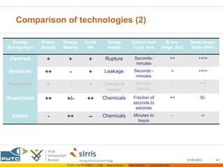
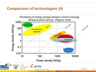
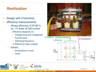
Hybridisatie door energie-opslag in of
          nabij de machine


                                seminarie 07-06-2012
                         Stephan.Masselis@sirris.be
                            Stijn.Goossens@fmtc.be


                the collective centre of the Belgian technological industry
Content

                      • Energy storage components
                                • Inertial energy storage (flywheel)
                                • Hydro-pneumatic enrgy storage
                                • Electric energy storage
                                     • Batteries
                                     • Capacitors & supercaps
                      • Electric energy conversion
                                • DC/DC &               active control
                      • Example


                                                                               07-06-2012   2
   © 2012 Sirris – FMTC – VUB   www.sirris.be   www.fmtc.be   mobi.vub.ac.be
Kinetic energy storage
       flywheels


                     the collective centre of the Belgian technological industry
Flywheels: Basics

                                                                                                             Ekin/Ekin_max for nominal max speed wn=1000
• Kinetic Energy:                                                                                   1
                                                                                                                                            wn          wn
                                                                                                   0.9                                       2           2

                                                                                                   0.8
     • Acceleration ( 2> 1): energy stored in flywheel
                                                                                                   0.7
     • Deceleration ( 2< 1): energy is released


                                                                                                                                      DOD
                                                                                                   0.6
     • Typical:      min   =    design_max/2                                        2
                                                                                        Ekin ( )
                                                                                                2 0.5                                                                      0.50
                                                                                         I wn
• DOD = Depth of Discharge                                                                         0.4


  SOC = State of Charge                 SOC (%)= 100 – DOD(%)                                      0.3
                                                                                                                                                                       0.250
                                                                                                   0.2


                                                                                                                                      SOC
• evolution of flywheels:                                                                          0.1


     • high speed                                                                                   0
                                                                                                         0     100     200   300   400      500   600   700    800   900     1000

     • smaller volume & lower mass
          flywheel             Low speed                           High speed
    rpm                        <10000                              15 000 – 100 000
    technology                 mature                              recent
    Rotor                      Steel (vmax≈300m/s)                 Composite fiber (vmax≈1000m/s)
    Bearing                    Conventional (heat)                 ceramic ; magnetic
    Surrounding                Air (air resistance)                Vacuum
    Safety                     !                                   !!!


                                                                                                                                                  07-06-2012                      4
                                      © 2012 Sirris – FMTC – VUB    www.sirris.be        www.fmtc.be                 mobi.vub.ac.be
Flywheels: evolution to higher speed and smaller sizes


                                                                           CCM (center for concepts in mechatronics)
                                                                             ‘Autotram’ project (with Fraunhofer)

                                                                                                07-06-2012        5
                © 2012 Sirris – FMTC – VUB   www.sirris.be   www.fmtc.be   mobi.vub.ac.be
Mechanical coupled flywheel

                                                                          •      Flywheel mechanical couped with drivetrain
                                                                                   •     Outcoming shaft  maintain vacuum for
                                                                                         highspeed flywheels !!
                                                                                   •     Brake energy recovery:
©FlybridSystems

                                                                                              rpmflywheel                    rpmdriveshaft


                                                                                                                CVT
                                                                                   •     No conversion needed to/from other energy
                                                                                         sources
                                                                                   •     Control of energy flows with mechanical
                                                                                         components (cvt/powersplit, clutches, …) is
                                                                                         challenging for efficiency & comfort (shocks,
                                                                                         response time… )
Test-setup for DriveTrain Control (DTC) testing (TU/e & mecHybrid)


                                             © 2012 Sirris – FMTC – VUB       www.sirris.be   www.fmtc.be   mobi.vub.ac.be
Kinetic Energy Recovery System (KERS) in F1

•   regulation: max 60 kWatt , max 400kJoule/lap
       (i.e. boost of 60kWatt during 6.7s)
•   F1 KERS from FlybridSystems
       • coupling to drivetrain via CVT (Torotrac)
       • total volume 13 litres                                                  ©FlybridSystems
       • weight 25 kg (Flywheel 5 kg)
       • 30000-60000 rpm
     • commercial mass production (Jaguar, end 2012/13)
        • 530 kJ (147 Wh) , 60 kW, < 40 kg
        • designed for 250000km lifetime
     • project with Volvo & SKF
•   others:
       • Zytec, Xtrac
       • Williams (electromechanical)


                                                                                                         07-06-2012   7
                             © 2012 Sirris – FMTC – VUB   www.sirris.be   www.fmtc.be   mobi.vub.ac.be
DriveTrain Innovations (NL):
    flywheel + ‘variomatic’ CVT+ planetary power split

•    ‘Zero Inertia Driveline‘ (TU Eindhoven)
      •   from ‘ecodrive’ project (late 90’s);
          goal: decreased fuel consumption + emission
           • load levelling
              Engine operates at optimal point
              flywheel = peak power unit
           • Stop and Go regimes:
              uncouple & Shut down ICE at low speed
      •   spin-off DriveTrain Innovations (dtinnovations.nl)
      •   Slower rpm, ‘classical’ technology

•    mecHybrid project:
      •   DTI+CCM+SKF+TU/e+Bosch+PunchPowertrain
      •   develop lowcost flywheel system for small/medium cars
      •   ‘small’ size (150kJ;30kW braking/10kW motoring)
      •   Focus on energy management (DTC = DriveTrain Control)


                                                                                                      07-06-2012   8
                          © 2012 Sirris – FMTC – VUB   www.sirris.be   www.fmtc.be   mobi.vub.ac.be
Electromechanical flywheel
             ‘mechanical capacitor’ , ’electromechanical battery’


•   flywheel integrated with motor/generator unit (MGU)
     •   permanent magnet motor or reluctance motor
                                  size reduction at high rpm
     •   power electronics
•   connection to electric supply
                             (grid or machine/vehicle DC-bus)
     •   mechanically uncoupled from machine/vehicle drivetrain
     •   can be mounted at any position
                                                                                                        15 kW motor
•   no shaft connection with exterior                                                                   (© Rosseta Technik)
          + easier to maintain vacuum                                                                   Top: 3000 rpm
          - thermal equilibrium of MGU in vacuum                                                        asyncronous motor

•   applications:                                                                                       Down: 35000rpm
                                                                                                        permanent magnet
     •   UPS-systems                                                                                    motor (only rotor)
     •   automotive / transport


                                                                                                           07-06-2012         9
                            © 2012 Sirris – FMTC – VUB   www.sirris.be   www.fmtc.be   mobi.vub.ac.be
Electromechanisch vliegwiel Rosseta Technik

Type T2 (orde 25 à 30 k€)                                                       Type T3  lowcost
Highpower (300-800W)                                                            Lowpower (3-5-10-15kW)
High energy: 4kWh (14.4 MJ)                                                     Low energy (~7sec @ max power)
New technology (25000rpm, vacuum)                                               Classic technology (6000rpm),


                                                                                                        07-06-2012   10
                            © 2012 Sirris – FMTC – VUB   www.sirris.be   www.fmtc.be   mobi.vub.ac.be
flywheel systems for UPS: Power-Thru
                             (= ex Pentadyne)
  • powerrating: 12sec @ 200kW (29sec @100kWatt)  ~667Wh (805Wh)
  • carbon fiber composite flywheel cylinder 24kg (cabinet 590kg)
        28Wh/kg (only rotor)  1.13Wh/kg (complete cabinet)
  • flywheel speed 52000 rpm; magnetic bearings
  • 250Watt nominal power consumption


pentadyne.com


                                                                                                  07-06-2012   11
                      © 2012 Sirris – FMTC – VUB   www.sirris.be   www.fmtc.be   mobi.vub.ac.be
flywheel systems for UPS: Vycon

• powerrating:
      model VDC:       30sec @ 100kW (max 215kW)  ~833Wh
      model VDC-XE: 19sec @ 160 kW (max 300kW)  idem
• high grade steel flywheel (? kg)
• flywheel speed 36000 rpm


                                                                                                 07-06-2012   12
                     © 2012 Sirris – FMTC – VUB   www.sirris.be   www.fmtc.be   mobi.vub.ac.be
Beaconpower : flywheel system for UPS & load
  levelling on grid
• model ‘Smart Energy 25 Flywheel’
• powerrating: 25kWh (15minutes @ 100kW)
• composite rotor (glass & carbon)
           ?kg (~2m high ! )                                                        powerplant NY: 15’ @ 20MWatt
                                                                                     (consists of 200 Flywheel units)
• flywheel speed 16000 rpm
• unit contained in concrete bunker


                                                                                                      07-06-2012        13
                       © 2012 Sirris – FMTC – VUB   www.sirris.be   www.fmtc.be   mobi.vub.ac.be
Transport: electromechanical flywheel for
         trams (Citadis, NL)
•   load leveling
     • load flywheel during braking & low power periods
     • unload during peak power requirements
•   autonomy
     •   No power supply over Erasmus bridge (Rotterdam)
•   specs:


                                                 CCM (center for concepts in mechatronics)


                                                                                                     07-06-2012   14
                         © 2012 Sirris – FMTC – VUB   www.sirris.be   www.fmtc.be   mobi.vub.ac.be
automotive electromechanical flywheels

•   Williams F1:
    •   50000-100000 rpm; 40kg unit;
    •   MLC Magnetically Loaded Composite
             technology from Urenco (nuclear power)
             efficiency load/unload: 97-99%
    •   Technical Center (Qatar) for development &
           commercialisation of flywheel technology
    •   prototype Porche911-GT3-R-hybrid
          • flywheel 6à8sec@120kW; 40000 rpm
          • 2x60kW motors on front axle

                                                                                      •     KINERSTOR PROJECT
                                                                                            (UK):
                                                                                               (William Hybrid Power, SKF,
                                                                                               Torotrac, landrover, e.o.)
                                                                                                Goal:
                                                                                           Mass market high speed
                                                                                            flywheel
                                                                                           Cost of less than £1,000
                                                                                           Development of both electric
                                                                                            and mechanic 07-06-2012
                                                                                                            flywheel      15
                           © 2012 Sirris – FMTC – VUB   www.sirris.be   www.fmtc.be   mobi.vub.ac.be
automotive electromechanical flywheels
                                                                    • Bosch (Motorsport) / Dynastore
•   Flybrid & Magneti Marelli
                                                                        •   160000 rpm !!
     •   530 kJ, 60 kW
                                                                        •   allways dual contraspinning units
     •   System weight: 27 kg
                                                                        •   750kJoule (208Wh) (set of 4)
                                                                        •   MGU 60kW (8kg)

                                                                                                            MGU


                                                                                         Control unit
                                                                                         water cooled


                                                                                                        07-06-2012   16
                           © 2012 Sirris – FMTC – VUB   www.sirris.be   www.fmtc.be   mobi.vub.ac.be
Flywheels: + and -


                     +                                                                 -
•   State of Charge (SoC)                                               •   Purchase cost
•   high energy & power density                                         •   Dedicated designs
     •   3-10 Wh/kg (w.r.t. total weight)                                    • limited combinations of power
     •   1000-3000 W/kg                                                         & energy
•   Low maintenance cost
                                                                             • not sold/available as such
•   Lifetime (order > 20 year) for big non-
                                                                        •   Standing losses
    mobile systems;
    automobile ? not proven yet                                         •   Safety issues
•   Performance not influenced by:                                      •   (Gyroscopic effect)
          • Amount of cycles                                                  •       for mobile applications
          • Depth of discharge                                                •       solve with 2 flywheels spinning in
          • Temperature or environment                                                opposite direction
•   high round-trip-efficiency (load/unload)


                                                                                                         07-06-2012    17
                           © 2012 Sirris – FMTC – VUB   www.sirris.be   www.fmtc.be     mobi.vub.ac.be
Hydraulic energy storage


                           the collective centre of the Belgian technological industry
Hydraulic energy storage: basic
        (‘hydro-pneumatic’ energy storage)
• Energy stored in accumulator
   •Most used: Piston and Bladder
   •Max press   350- 400 bar…500bar
   •preload pressure:
        100 … 200 bar


•More energy/power needed ?
   accumulators in parallel


   •   Flow rates                                  5000- 45000 l/min                             900 l/min
       (order of magnitude)


                                                                                                    07-06-2012   19
                     © 2012 Sirris – FMTC – VUB   www.sirris.be   www.fmtc.be   mobi.vub.ac.be
Hydraulic energy storage
     advantages & disadvantages
                                                           low energy density
high power density
lifetime                                                   Size & weight for mobile
maintenance                                                applications (passenger cars)
lower cost (ROI) ?                                         thermal effects gas chamber
 ( 1700 €, 20 liter bladdertype)                           (piston type -> standing losses)
mature technology
                                                           (Leakage)
 -   no really new technology
                                                           Cost/efficiency of aggregates
 -   but: new applications


      Light-weight carbon fibre
      reinforced accumulators


                                                                                                07-06-2012   20
                    © 2012 Sirris – FMTC – VUB   www.sirris.be   www.fmtc.be   mobi.vub.ac.be
Hydraulic energy storage: thermal aspect
(example Hydac)


                                                                                              07-06-2012   21
                  © 2012 Sirris – FMTC – VUB   www.sirris.be   www.fmtc.be   mobi.vub.ac.be
Hydraulic energy storage Example: HyDrid

    • Series hybrid
      • regeneration
      • load leveling

    • Standard Car: 1450 kg
    • Accumulator: 20 liter


                                                                                         http://www.innas.com/


                                                                                          07-06-2012         22
             © 2012 Sirris – FMTC – VUB   www.sirris.be   www.fmtc.be   mobi.vub.ac.be
Hydraulic energy storage Example: HyDrid


•   Goal: work in optimal operational condition of ICE
     •   Also effective on highway !


                                                                                              07-06-2012   23
                  © 2012 Sirris – FMTC – VUB   www.sirris.be   www.fmtc.be   mobi.vub.ac.be
Hydraulic energy storage: UPS-van

             •series hybrid
             • power density ~3000W/kg
             • energy density ~2Wh/kg


                                                                                         07-06-2012   24
             © 2012 Sirris – FMTC – VUB   www.sirris.be   www.fmtc.be   mobi.vub.ac.be
Hydraulic energy storage: commercial truck

•   Bosch-Rexroth
    •   parallel hydr.system:
         • 500kg
         • 2 x32liter bladder
            accumulator (210-330bar)
    • 250kWatt  500W/kg
    • 550kJoule(153Wh ) 0.3Wh/kg
        (= Ekin of vehicle ~16ton @30km/h)
    •   fuel reduction 25%


                                                                                                       07-06-2012   25
                           © 2012 Sirris – FMTC – VUB   www.sirris.be   www.fmtc.be   mobi.vub.ac.be
Hydraulic energy storage :
suppliers in automotive/transport sector

•   Bosch-Rexroth HRB (Hydraulic Regenerative Braking)
•   Eaton Corp: Hydraulic Launch Assist (HLA)
•   Parker Hannifin: RunWise Advanced Series
•   Hydraulic Hybrid Systems,LLC (HHS)
     •   light-duty vehicles
     •   average price parallel system: $12,900
•   Artemis Intelligent Power (Digital Displacement © system)
•   Hydac  accumulators (+ calculator)


                                                                                                   07-06-2012   26
                       © 2012 Sirris – FMTC – VUB   www.sirris.be   www.fmtc.be   mobi.vub.ac.be
Electric energy storage:

 batteries
 capacitors
 supercaps (ultracaps)


                           the collective centre of the Belgian technological industry
batteries
     lead acid
     nickel based
     lithium based
     …


                     the collective centre of the Belgian technological industry
Lead-acid batteries
•    simpel ‘vented’             VRLA                    advanced VRLA
          (VRLA = valve-regulated lead-acid)
•    Specs
      • Low Energydensity (30-40 Wh / kg)
      • Self discharge 2 % / month
      • Small lifetime
           • VRLA: 500-800 cycle
           • Vented: 1000-1500 cycles
      • Efficiency 70-85 %
      • cheap (1kWh ~$250)


•    Advanced VRLA (longer lifetime, higher power)
      • micro/mild hybrid (start-stop function in cars)
      • The Advanced Lead-Acid Battery Consortium (http://www.alabc.org)


                                                                                                    07-06-2012   29
                        © 2012 Sirris – FMTC – VUB   www.sirris.be   www.fmtc.be   mobi.vub.ac.be
Ni-based batteries  NiMH

•   Used in hybrids
    •   Toyota prius, Honda Insight, …
•   Specs
    • E 80 Wh/kg
    • P 170-1000 W/kg
    • Standing losses 10 % month
    • Efficiency: 70-80 %


•   Others
    •   NiCd, NiZn


                                                                                                  07-06-2012   30
                      © 2012 Sirris – FMTC – VUB   www.sirris.be   www.fmtc.be   mobi.vub.ac.be
Lithium based batteries                                                                         May 2009 A. Burke


•   A lot of different types
     • Li-ion based
     • Li-polymer based


•   Different applications:
     • High power Li-batteries
     • High energy Li-batteries


•   Specs
     • Broad power/energy range see table
     • Li: reactive element
          •  thermal monitoring/management
     •   expensive


                                                                                                            07-06-2012   31
                        © 2012 Sirris – FMTC – VUB   www.sirris.be   www.fmtc.be   mobi.vub.ac.be
NaNiCl - batteries (Zebra)

•   Specs
    •   good energy & power density
         • E   100 -125 Wh/kg
         • P   150-180 W/kg
    •   Disadvantage:
         • High operating temp needed (270-330 °C)
         • Needs extra heating at shut down
    •   Good solution for intensively used vehicles


                                                                                                 07-06-2012   32
                     © 2012 Sirris – FMTC – VUB   www.sirris.be   www.fmtc.be   mobi.vub.ac.be
Lithium-Ion Capacitor (LIC)

•   ‘Hybrid’ or ‘Pseudo’-capacitors
    •    Ex.: JSR Micro (Leuven)
•   Technology batteries and electrolytic capacitor
     • Positive electrode: reaction similar to battery
     • Negative electrode: Layer phenomena
     •  higher energy density
     • Earlier stage of development
•   Specs
     • Lifetime: +- 100 000 cycles
     • Less self-discharge (compared to supercaps)
     • Temperature window (better than batteries)
     • High cell voltage 3,8 V


                                                                                                      07-06-2012   33
                          © 2012 Sirris – FMTC – VUB   www.sirris.be   www.fmtc.be   mobi.vub.ac.be
Summary batteries
                                                                             (VUB-Mobi             econocap)


                +                                                                            -
•   High energy densitiy                               •      Limited lifetime (+- 1000 cycles)
•   Low self discharge                                         •   Depends on temperature
                                                               •   Depth of discharge
                                                       •      Limited temperature range
                                                       •      More difficult to determine SOC
                                                              (+- constant voltage)
                                                       •      Power density (type dependigin)
                                                                                                      07-06-2012   34
                       © 2012 Sirris – FMTC – VUB   www.sirris.be   www.fmtc.be   mobi.vub.ac.be
 capacitors
     supercaps/ultracaps
     electrolytic capacitor
     …


                              the collective centre of the Belgian technological industry
Supercapacitors (EDLC):
        what & how
•    EDLC = Electric (Electrochemical) Double Layer Capacitor
•    Principle:                                                                                           d
      • Charge separation (order of nanometers ) (d ↓)                                                    A
      • Extension surface: ex. porous carbon (A↑)                                                         C 


                                                               from Wikipedia
               C~ 10’s F --. 10’s mF               C~ 10’s F --. few kF


                                                                                                  07-06-2012     36
                      © 2012 Sirris – FMTC – VUB   www.sirris.be   www.fmtc.be   mobi.vub.ac.be
Supercapacitors facts

•   Typical voltage cell:
         2,5 - 2,7 V
          Series connection required
•   Tolerance on capacitance + series connection
          voltage balancing needed !
         • Different methods: passive & active
         • Modules with balancing commercially available

•   Self-discharge                                                                   Bron:VUB-mobi


                                                                                                     07-06-2012   37
                         © 2012 Sirris – FMTC – VUB   www.sirris.be   www.fmtc.be   mobi.vub.ac.be
Supercaps: Still fork-lifts


                                                                                         07-06-2012   38
             © 2012 Sirris – FMTC – VUB   www.sirris.be   www.fmtc.be   mobi.vub.ac.be
Supercaps: Dana hybrid transmission

        transmission
          (gear box)
  MGU


                             balanced
                            supercaps                         Duty cycle


                                                              1  driving backward
                                                              2  forward, at end empty carrier
             inverter /                                       3  backward
            MGU-drive                                         4  forward, at end load carrier


                                                                                            07-06-2012   39
                © 2012 Sirris – FMTC – VUB   www.sirris.be   www.fmtc.be   mobi.vub.ac.be
Electrolytic capacitors
•    lot of different types
•    Aluminum capacitors most relevant for energy storage
      • capacity up to 20 mF
      • max voltage 400 à 500 V  2 in serie for industrial DC-bus
•    lifetime: 1.000.000’s of cycles, BUT depends from:
      temperature T
      •   Arrhenius approximation: lifetime halves every 10°C increase of T
•     amplitude ripple current IAC
      •   higher amplitude  shorter lifetime
•     frequency of ripple current (frequency of load/unload)
      •   higher frequency  higher lifetime
•     (smaller) effect of actual maximum voltage level
      •   Vmax higher  lower lifetime


                                                                                                    07-06-2012   40
                        © 2012 Sirris – FMTC – VUB   www.sirris.be   www.fmtc.be   mobi.vub.ac.be
Electrolytic capacitors: lifetime

•    strongly T and thus ESR-dependent (heating Q~ESR*IRMS2)
      • ESR = Equivalent Series Resistance
      • ESR ⇗⇗ at low frequencies (<100Hz)  Temp ⇗⇗  lifetime ⇘ ⇘
                 datasheets give data >50Hz or > 20Hz

                  much mechanical systems have cycles < 10Hz
                ESR-curves in data-sheet                                      extrapolation for low frequencies


                                                                                                       07-06-2012   41
                      © 2012 Sirris – FMTC – VUB   www.sirris.be       www.fmtc.be   mobi.vub.ac.be
Electrolytic capacitors: lifetime (cont’d)

•   ‘End of Life’ when any of the following conditions is reached:
     •   Core temp > 105 °C (85°C products)
                     > 120 °C (105°C products)
     •   ESR > 2 x initial ESR
     •   Capacitance change: decrease more than10 or 20% relative to initial value
     •   Leakage current < initial limit

•   Conclusion:
     •   Design with low ESR !!! However forced cooling often necessary
     •   Limit current in capacitors  ‘oversizing’
     •   Pay attention to balancing + limit inrush current at startup
         + safely unload capacitors at shutdown of the machine

•   Remark concerning supercaps: same thermal problem, however
     •   minor frequency dependency (ratio ESRDC / ESR1000Hz ≌ 2)
     •   mostly application with high power  high currents  forced cooling


                                                                                                      07-06-2012   42
                          © 2012 Sirris – FMTC – VUB   www.sirris.be   www.fmtc.be   mobi.vub.ac.be
Other capacitors

•   Keramic capacitors: 4V-…-600V-…-50 kV
         • Small capacitance
         • Smaller lifetime (order of magnitude ~1000 hr)
         • Suited for high frequencies @ (very) high voltage


•   Metallized film capacitors
     • higher voltage >1000 V  no series connection required
     • Low capacitance (max. ~1000 F)
     • high frequency/low energy


                                                                                                 07-06-2012   43
                     © 2012 Sirris – FMTC – VUB   www.sirris.be   www.fmtc.be   mobi.vub.ac.be
other energy storage components:
                                          MDI Airpod
 pneumatic                                accumulator:
                                             175l @350bar
                                              carbonfibre
 superconducting magnetic energy storage (SMES)


 hydrogen (H2)
 …


                                      the collective centre of the Belgian technological industry
Comparison of technologies


                        the collective centre of the Belgian technological industry
Comparison of technologies (2)

   Energy      Power     Energy       Cycle             Safety           Typical load           Know-        Temp.range /
Storage type   density   density       life             assets            cycle time          ledge SoC       Temp effect

 Flywheel        +         +             +             Rupture              Seconds-                   ++          ++/+
                                                                             minutes
 Hydraulic      ++          -            +             Leakage             Seconds -                   +           ++/+
                                                                            minutes
Pneumatic        +          -            +             ‘pressure             Minutes                   +            ++/-
                                                         vessle’             (hours)

(Super)caps     ++        +/-           ++         Chemicals               Fraction of                 ++            0/-
                                                                           seconds to
                                                                            seconds
  battery         -       ++             --        Chemicals               Minutes to                  -             -/-
                                                                             hours


                                                                                                            07-06-2012     47
                          © 2012 Sirris – FMTC – VUB    www.sirris.be   www.fmtc.be   mobi.vub.ac.be
Comparison of technologies (4)

      Positioning of energy storage devices in terms of energy
              density & power density (Ragone chart)


                                                                  Supercaps
                                                                      Hydraulic


                                                                                          07-06-2012   49
              © 2012 Sirris – FMTC – VUB   www.sirris.be   www.fmtc.be   mobi.vub.ac.be
Electrical energy conversion (DC-converter)

stijn.goossens@fmtc.be


                         the collective centre of the Belgian technological industry
Content


•   Introduction
     • Why dc/dc-converter
     • Market situation
•   Topology DC-converter
     • basics
     • Interleaved multi-channel DC-converter
•   DC-converter prototype in EnSto project


                                                                                                07-06-2012   51
                    © 2012 Sirris – FMTC – VUB   www.sirris.be   www.fmtc.be   mobi.vub.ac.be
Typical electrical driveline

     •   Rectifier
          • Rectification electricity grid / dieselgenerator / …
          • High dc-bus voltage
               • Depending on type of supply, country, …
               • Typical 550 V, 650 V (stationary applications)
     •   Several inverters + motors
          • Connected on dc-bus
     •   Brake chopper
          • dissipate energy when Vdc gets too high
     •   High dc-bus voltage
          • Depending on type of supply, country, …
          • Typical 550 V, 650 V (stationary applications)

•    Energy saving
       store energy in supercaps


                                                                                                      07-06-2012   52
                          © 2012 Sirris – FMTC – VUB   www.sirris.be   www.fmtc.be   mobi.vub.ac.be
Compatibility: Supercaps  DC-bus
•    Voltage match DC-bus – Supercaps:
      •   Supercaps require big voltage swings
          to fully exploit energy
           • Energy exchange  Voltage changes
           • Typical (maximum) voltage window: ½ Vmax to Vmax
      •   Limited voltage changes on DC-bus driveline (e.g. 550V to 750V)
•    Number of cells
      • Low cell voltage supercaps:
      • typical max. 2.5 – 2.7 V
      •  Put cells in series to match dc-bus
           Not automatically matched with amount of energy!
•    Interface needed to transform voltages
      • DC to DC converter
      • Also valid for battery systems or combined


                                                                                                    07-06-2012   53
                        © 2012 Sirris – FMTC – VUB   www.sirris.be   www.fmtc.be   mobi.vub.ac.be
Energy management

•   Example: driveline with combustion engine + generator
    •   cranes, cars,…
         • Fuel + energy storage
    • Efficiency engine depends on load
    • Increase efficiency
         1. Recuperate brake energy
         2. Operate in good working point


    •    control of powerflows needed
         • To obtain optimal efficiency
                                                                                 Bron: http://www.innas.com
         • Implement Energy Management Strategy

•   Energy management impossible without dc-converter


                                                                                                              07-06-2012   54
                      © 2012 Sirris – FMTC – VUB   www.sirris.be   www.fmtc.be   mobi.vub.ac.be
Disadvantage dc-converter

•   Extra component
    •   Extra losses
         • Losses when charging
         • Losses when discharging
         • Efficient dc-converter important                         discharging                    charging
    •   Extra cost
         • Trade-off between
              • more supercaps and dc-converter


                                                                                                   07-06-2012   55
                       © 2012 Sirris – FMTC – VUB   www.sirris.be   www.fmtc.be   mobi.vub.ac.be
dc-converter advantages & disadvantages

•   Advantages
    •   Control of powerflows
         • Impossible without dc-converter (in series hybrid)
         • Allows optimisation of system efficiency (power management strategies)
    •   Downsizing supercaps possible
         • Less cells required
         • Increased energydensity (vary voltage from Vmax to ½ Vmax)
    •   Protection (avoid peakcurrents in energy storage)
•   Disadvantages
    • Extra losses: dc-converter with good efficiency is important
    • Extra cost: trade-off between more supercaps / efficiency gain  dc-
      converter


                                                                                                  07-06-2012   56
                      © 2012 Sirris – FMTC – VUB   www.sirris.be   www.fmtc.be   mobi.vub.ac.be
Market situation
•   Used in automotive
    • Ex. Toyota Prius e.a.
    • Mainly in-house developments, not for sale 
•   Commercial products
    •   A lot ‘off-the-shelf’ products in low voltage range
        (range of 12 - 24 - 48 - …V)
•   High voltage dc-converters ?
    •   Rarely found off-the-shelf  expensive, custom made
        (every application is different and has different specifications:
               voltages / currents / sizes / cost / targeted efficiencies)
           Study of DC-conversion in EnSto-project:
               • Gain knowhow in dc-converters / powerelectronics
               • Focus on high power / high voltages
               • Validate experimentally on set-up / prototype


                                                                                                  07-06-2012   57
                      © 2012 Sirris – FMTC – VUB   www.sirris.be   www.fmtc.be   mobi.vub.ac.be
DC-converter basics

•   Bidirectional DC-converter
     •   2 high frequent switches
           • IGBTs / mosfets / …
           • With anti-parallel diode
     •   1 inductor
     •   filtercapacitors on both sides
     •   Vdc>Vsc
     •   buck mode: power from high to low voltage
         boost mode: power from low to high voltage
•   Example charging supercaps (buck mode)
     •   Top switch on      1
           • current inductor increases
     •   Top switch off    2
           • Bottom diode conducts
           • Current inductor decreases

     •   Current = Idc + Iripple


                                                                                                        07-06-2012   58
                            © 2012 Sirris – FMTC – VUB   www.sirris.be   www.fmtc.be   mobi.vub.ac.be
DC-converter topologies

•     Different topologies exist (not detailed further)


    Source: Monzer Al Sakka, VUB, Comparison of 30KW DC/DC Converter topologies interfaces for fuel cell in
    hybrid electric vehicle


        •   Interleaved multi-channel DC-DC converter most promising
              • Good efficiency and small volume


                                                                                                           07-06-2012   59
                               © 2012 Sirris – FMTC – VUB   www.sirris.be   www.fmtc.be   mobi.vub.ac.be
Interleaved multi-channel DC-converter

                                                                                                               Ex. 3 branches
•   Multi-channel ?
    • multiple buck-boost converters in parallel


                                                                          High Voltage
    • total current is split in different branches


                                                                                                                             Low Voltage
                                                                                                                             (supercaps)
•   Interleaved ?
    • The currents of each branch are shifted from each
      other
          • Origin of name ‘interleaved’
          • Ex. 3 branches  each current shifted 1/3 of the
            period


                                                                                                                07-06-2012    60
                             © 2012 Sirris – FMTC – VUB   www.sirris.be         www.fmtc.be   mobi.vub.ac.be
Advantages of splitting in multiple branches

•   Increased efficiency
     •   Reduction of conduction losses (Ri2) in inductors, IGBTs, diodes
          • Average currents per branch decrease (current splitted in N branches)


•   Size inductors decreases
     •   Current splitted in N branches
          • Rough approximation:
          • Volume inductor ~ related to energy in inductor =
               • Total energy in coils:


           Energy and thus total inductor volume proportional with 1/N
           Reduction in size and price


                                                                                                    07-06-2012   61
                        © 2012 Sirris – FMTC – VUB   www.sirris.be   www.fmtc.be   mobi.vub.ac.be
Advantages: effect of interleaving

               •   Effect of interleaving
                    • Reduction ripple current at energy storage
                    • Output ripple current reduction + increased frequency of ripple
                    • To get the same input and output ripples:
                       Smaller filtercapacitors needed (compared to 1 branch converter
High Voltage


                                                        Low Voltage
                                                        (supercaps)


                                                                                                                     07-06-2012   62
                                   © 2012 Sirris – FMTC – VUB         www.sirris.be   www.fmtc.be   mobi.vub.ac.be
Summary advantages of interleaved converter

•   Good efficiency feasible
•   Small filters needed (capacitors, inductors)
     • Small volume and weight, reduced price
     • Faster dynamic response (faster transients currents possible)


•   Modular system
     • More power needed?  Extra branches can be ‘added’ to the system
     • No need to redesign inductors etc. again from scratch


                                                                                                 07-06-2012   63
                     © 2012 Sirris – FMTC – VUB   www.sirris.be   www.fmtc.be   mobi.vub.ac.be
Prototype DC-converter

•     Specifications
       • Possible to charge and discharge supercaps
       • Voltages
            • Low voltage (supercaps): 300 - 650 V @ 360A (≈ 110 – 230 kW)
            • High voltage (DC-bus):            up to 800 V
       •   Weight / size
            • Less relevant, stationary application
       •   High efficiency


•     Realisation
    Together with member company Bluways


                                                                                                         07-06-2012   64
                             © 2012 Sirris – FMTC – VUB   www.sirris.be   www.fmtc.be   mobi.vub.ac.be
Controller/Interfacing etc.
    Realisation

•   Design with 3 branches
•   efficiency measurements
    •   Shows efficiency of 97-98 %
        ca. 1% lower at half current
         Efficiency depends on:
         • Voltage level and voltageratio
         • Current level                               6 IGBTs (watercooled)
                                                                                                      3 inductors
         • Switching frequency                               + drivers
          Efficiency maps created
    •   Issues:
         • temperature in coils
         • noise


                                                                                                       07-06-2012   65
                          © 2012 Sirris – FMTC – VUB   www.sirris.be   www.fmtc.be   mobi.vub.ac.be
Conclusion

•   DC-converter
    •   Working prototype
         • Issues identified and tackled
         • Good efficiencies are obtained
    •   Allows to implement power management strategies
•   Prototype  product
    • Further development done by bluways
    • Commercial product now successfully put on market


                                                                                                  07-06-2012   66
                      © 2012 Sirris – FMTC – VUB   www.sirris.be   www.fmtc.be   mobi.vub.ac.be
Ongoing work

•   Other inductor configurations
     • Coupled inductors
     • Mutual coupling between branches can lead to material/price-reduction


•   Efficiency
     •   Efficiency can still be improved at lower currents by selecting number of
         branches ifo load


                                                                                                  07-06-2012   67
                      © 2012 Sirris – FMTC – VUB   www.sirris.be   www.fmtc.be   mobi.vub.ac.be
Voorbeeld van elektrische energieopslag bij
   machine met harmonische cyclische
                beweging


                        the collective centre of the Belgian technological industry
Elektrische energie-opslag: technologie

Electrolytic capacitors
→ Small energy density (indication: around 0,5 Wh/kg)
→ Very high lifetime possible (10 year and more / 100 millions of cycles possible)
→ high voltage per cell (typical 400V, up to >1000V for some types);
→ capacity per cell: 100 F < C < 10’s mF

Super-capacitors
→ High power density, low energy density
    Orders of magnitude: 5 Wh/kg, 6 kW/kg (depending on efficiency) at cell level)
→ High lifetime possible (500 000-1 000 000 cycles).
→ low voltage per cell (typical 2.7V);
→ capacity per cell typical 10's F < C < few kF

Batteries
→ high energy and energy density; rather low power characteristics
       (at cell level 50-150-200...400 Wh/kg possible depending on the batterytype)
→ Short lifetime (order of magnitude 500-2000 cycles for full charge/discharge)
→ low voltage per cell (typical 1.2 à 3.5 V)


                                                                                                     07-06-2012   69
                         © 2012 Sirris – FMTC – VUB   www.sirris.be   www.fmtc.be   mobi.vub.ac.be
Elektrische energie-opslag: topologie
DC-Bus + Storage technology (Energy storage directly on DC-bus)
→ 'passive' configuration

DC-Bus + DC/DC-Converter + Storage technology (Energy storage coupled to DC-bus via DC/DC
converter)

More difficult to indicate when to use and when not to use DC/DC-converter. Some guidelines:

Coupling via DC/DC-Converter allows for:
    → different (independent) voltage levels for energy storage components and drive DC-powerline
    → energy management ('active' control of the power flows)
             Control of power flows allows for fully use of potential of capacitor (deeper discharge possible),
             implement strategy (maximize energy recuperation, load leveling), better control of battery
SOC...
Choosing a dc-dc converter will be cost effective when having a big package of supercaps.
    → for small packages it is more difficult to say if a dc-dc converter is cost effective.
       (trade-off between price of the supercap package and price dc-converter)

Combination of technologies: Following topologies have been identified:
      DC-Bus + Batteries + Super-capacitors
      DC-Bus + Batteries + DC/DC-Converters + Super-capacitors
      DC-Bus + High energy batteries + DC/DC converter + High power batteries


                                                                                                           07-06-2012   70
                               © 2012 Sirris – FMTC – VUB   www.sirris.be   www.fmtc.be   mobi.vub.ac.be
Elektrische energieopslag:
         workflow
 •   Workflow bij gebruik van cellen
     (electrolytische capaciteiten, supercaps of
     batterijcellen) voor energieopslag, direct
     gekoppeld aan DC-bus.

 •   Indien men de werkspanning kan kiezen (bij
     gebruik van DC-omvormer, of bij een apart
     systeem van MGU gekoppeld op aandrijflijn
     met vermogensomzetter), dan de gekozen
     spanningsrange toepassen (Vmax, Vmin).

 •   Keuze technologie-topologie (eerste stap): bij
     machines met frequente cycli => capaciteiten
     (batterij meestal geen optie wegens lage
     levensduur en/of beperkte stromen
     (vermogen)


                                                                                                        07-06-2012   71
                            © 2012 Sirris – FMTC – VUB   www.sirris.be   www.fmtc.be   mobi.vub.ac.be
cyclische beweging (kinetische energie)
                                                                    Theoretical power needs for mechanism
•   Basisgegevens
     • vermogenspiek ≌32 kW
     • energie ≌2200 Joule
     • frequentie: ≌ 5Hz
     • grid: 3x380V~;
       DC-bus: 600…max800V
•   doel: ‘negatief’ vermogen recupereren

•   Oplossing (na enkele iteraties):
     technologie:
        electrolytische capaciteiten (20mF, 400V max)
        (2 in serie, 5 parallel)
     topologie:     passief (zonder DC/DC converter)


                                                                                                   07-06-2012   72
                       © 2012 Sirris – FMTC – VUB   www.sirris.be   www.fmtc.be   mobi.vub.ac.be
cyclische beweging: simulatie

•   werkelijke vereiste & recupereerbare vermogens:
         rendementen frequentiesturing, motor, tandwieloverbrenging
         mechanische verliezen in systeem (wrijving)
         efficiëntie capaciteiten
     Werkelijke vermogens & energieën:
         4100 Joule vereiste energie per cyclus ; 1200 Joule gerecupereerd (29%)
         vereist vermogen uit net: > 60kW piek;


                                                                                                     07-06-2012   73
                         © 2012 Sirris – FMTC – VUB   www.sirris.be   www.fmtc.be   mobi.vub.ac.be
cyclische beweging: levensduur capaciteiten

•    invloedsfactoren:
           stroom ⇗                     levensduur ⇘
           frequentie ⇘                 levensduur ⇘ (specs. datasheets slechts > 10 of 20Hz)
           spanning over caps. ⇗           levensduur ⇘
           temperatuur ⇗                levensduur ⇘ (10°⇗  halveren levensduur !)
•    levensduurschatting  meer dan 10 jaar
        op basis van specificaties datasheets (levensduur i.f.v. Temp bij ref.spanning)
            vereist (benaderende) berekening Temp i.f.v. stroom (IRMS)
            vereist kennis van ESR-waarde i.f.v. frequentie
               !! in datasheets slechts boven 10, 20 of 50 Hz  mechanische systemen lagere frequentie !!
            correctie i.f.v. werkelijk optredende maximale spanning over capaciteit
     Opmerking:
        puur energetisch reeds voldoende met 1 tak van 2 capaciteiten in serie
        omwille van levensduur en max spanning (<750V) tot 5 takken gekomen
          (meestal oversizing nodig bij electrolythische caps omwille van levensduur)


                                                                                                          07-06-2012   74
                              © 2012 Sirris – FMTC – VUB   www.sirris.be   www.fmtc.be   mobi.vub.ac.be
cyclische beweging: tot slot…

•   pay-back:
      kostprijs capaciteit: ±€95 *10  €950
      energie-recuperatie: 6kW gemiddeld (5*1200 Joule/seconde)
       6kW*8u/dag*5dag/week*52weken/jaar* € 0.15/kWh = €1872
      payback ongeveer half jaar
•   alternatieven:
      supercaps of batterij => te veel cellen nodig in serie en/of DC-convertor 
         zowiezo veel duurder
•   verdere opmerkingen:
     •   mogelijke strategie (mits DC/DC converter en actieve controle over
         vermogensstromen; hier niet uitgevoerd): load levelling
           energie in capaciteiten niet onmiddelijk benutten,
            maar op moment van piekvermogen
     •   belang van rendementen (vb motor)  werkt in 2 richtingen !!


                                                                                                      07-06-2012   75
                          © 2012 Sirris – FMTC – VUB   www.sirris.be   www.fmtc.be   mobi.vub.ac.be
Dank u !! Vragen ??


                                                                            07-06-2012   76
© 2012 Sirris – FMTC – VUB   www.sirris.be   www.fmtc.be   mobi.vub.ac.be

Hybridisatie van mijn machine - 07-06-2012_components-dc-example

  • 1.
    Hybridisatie door energie-opslagin of nabij de machine seminarie 07-06-2012 Stephan.Masselis@sirris.be Stijn.Goossens@fmtc.be the collective centre of the Belgian technological industry
  • 2.
    Content • Energy storage components • Inertial energy storage (flywheel) • Hydro-pneumatic enrgy storage • Electric energy storage • Batteries • Capacitors & supercaps • Electric energy conversion • DC/DC & active control • Example 07-06-2012 2 © 2012 Sirris – FMTC – VUB www.sirris.be www.fmtc.be mobi.vub.ac.be
  • 3.
    Kinetic energy storage flywheels the collective centre of the Belgian technological industry
  • 4.
    Flywheels: Basics Ekin/Ekin_max for nominal max speed wn=1000 • Kinetic Energy: 1 wn wn 0.9 2 2 0.8 • Acceleration ( 2> 1): energy stored in flywheel 0.7 • Deceleration ( 2< 1): energy is released DOD 0.6 • Typical: min = design_max/2 2 Ekin ( ) 2 0.5 0.50 I wn • DOD = Depth of Discharge 0.4 SOC = State of Charge SOC (%)= 100 – DOD(%) 0.3 0.250 0.2 SOC • evolution of flywheels: 0.1 • high speed 0 0 100 200 300 400 500 600 700 800 900 1000 • smaller volume & lower mass flywheel Low speed High speed rpm <10000 15 000 – 100 000 technology mature recent Rotor Steel (vmax≈300m/s) Composite fiber (vmax≈1000m/s) Bearing Conventional (heat) ceramic ; magnetic Surrounding Air (air resistance) Vacuum Safety ! !!! 07-06-2012 4 © 2012 Sirris – FMTC – VUB www.sirris.be www.fmtc.be mobi.vub.ac.be
  • 5.
    Flywheels: evolution tohigher speed and smaller sizes CCM (center for concepts in mechatronics) ‘Autotram’ project (with Fraunhofer) 07-06-2012 5 © 2012 Sirris – FMTC – VUB www.sirris.be www.fmtc.be mobi.vub.ac.be
  • 6.
    Mechanical coupled flywheel • Flywheel mechanical couped with drivetrain • Outcoming shaft  maintain vacuum for highspeed flywheels !! • Brake energy recovery: ©FlybridSystems rpmflywheel rpmdriveshaft  CVT • No conversion needed to/from other energy sources • Control of energy flows with mechanical components (cvt/powersplit, clutches, …) is challenging for efficiency & comfort (shocks, response time… ) Test-setup for DriveTrain Control (DTC) testing (TU/e & mecHybrid) © 2012 Sirris – FMTC – VUB www.sirris.be www.fmtc.be mobi.vub.ac.be
  • 7.
    Kinetic Energy RecoverySystem (KERS) in F1 • regulation: max 60 kWatt , max 400kJoule/lap (i.e. boost of 60kWatt during 6.7s) • F1 KERS from FlybridSystems • coupling to drivetrain via CVT (Torotrac) • total volume 13 litres ©FlybridSystems • weight 25 kg (Flywheel 5 kg) • 30000-60000 rpm • commercial mass production (Jaguar, end 2012/13) • 530 kJ (147 Wh) , 60 kW, < 40 kg • designed for 250000km lifetime • project with Volvo & SKF • others: • Zytec, Xtrac • Williams (electromechanical) 07-06-2012 7 © 2012 Sirris – FMTC – VUB www.sirris.be www.fmtc.be mobi.vub.ac.be
  • 8.
    DriveTrain Innovations (NL): flywheel + ‘variomatic’ CVT+ planetary power split • ‘Zero Inertia Driveline‘ (TU Eindhoven) • from ‘ecodrive’ project (late 90’s); goal: decreased fuel consumption + emission • load levelling  Engine operates at optimal point  flywheel = peak power unit • Stop and Go regimes:  uncouple & Shut down ICE at low speed • spin-off DriveTrain Innovations (dtinnovations.nl) • Slower rpm, ‘classical’ technology • mecHybrid project: • DTI+CCM+SKF+TU/e+Bosch+PunchPowertrain • develop lowcost flywheel system for small/medium cars • ‘small’ size (150kJ;30kW braking/10kW motoring) • Focus on energy management (DTC = DriveTrain Control) 07-06-2012 8 © 2012 Sirris – FMTC – VUB www.sirris.be www.fmtc.be mobi.vub.ac.be
  • 9.
    Electromechanical flywheel ‘mechanical capacitor’ , ’electromechanical battery’ • flywheel integrated with motor/generator unit (MGU) • permanent magnet motor or reluctance motor  size reduction at high rpm • power electronics • connection to electric supply (grid or machine/vehicle DC-bus) • mechanically uncoupled from machine/vehicle drivetrain • can be mounted at any position 15 kW motor • no shaft connection with exterior (© Rosseta Technik) + easier to maintain vacuum Top: 3000 rpm - thermal equilibrium of MGU in vacuum asyncronous motor • applications: Down: 35000rpm permanent magnet • UPS-systems motor (only rotor) • automotive / transport 07-06-2012 9 © 2012 Sirris – FMTC – VUB www.sirris.be www.fmtc.be mobi.vub.ac.be
  • 10.
    Electromechanisch vliegwiel RossetaTechnik Type T2 (orde 25 à 30 k€) Type T3  lowcost Highpower (300-800W) Lowpower (3-5-10-15kW) High energy: 4kWh (14.4 MJ) Low energy (~7sec @ max power) New technology (25000rpm, vacuum) Classic technology (6000rpm), 07-06-2012 10 © 2012 Sirris – FMTC – VUB www.sirris.be www.fmtc.be mobi.vub.ac.be
  • 11.
    flywheel systems forUPS: Power-Thru (= ex Pentadyne) • powerrating: 12sec @ 200kW (29sec @100kWatt)  ~667Wh (805Wh) • carbon fiber composite flywheel cylinder 24kg (cabinet 590kg) 28Wh/kg (only rotor)  1.13Wh/kg (complete cabinet) • flywheel speed 52000 rpm; magnetic bearings • 250Watt nominal power consumption pentadyne.com 07-06-2012 11 © 2012 Sirris – FMTC – VUB www.sirris.be www.fmtc.be mobi.vub.ac.be
  • 12.
    flywheel systems forUPS: Vycon • powerrating: model VDC: 30sec @ 100kW (max 215kW)  ~833Wh model VDC-XE: 19sec @ 160 kW (max 300kW)  idem • high grade steel flywheel (? kg) • flywheel speed 36000 rpm 07-06-2012 12 © 2012 Sirris – FMTC – VUB www.sirris.be www.fmtc.be mobi.vub.ac.be
  • 13.
    Beaconpower : flywheelsystem for UPS & load levelling on grid • model ‘Smart Energy 25 Flywheel’ • powerrating: 25kWh (15minutes @ 100kW) • composite rotor (glass & carbon) ?kg (~2m high ! ) powerplant NY: 15’ @ 20MWatt (consists of 200 Flywheel units) • flywheel speed 16000 rpm • unit contained in concrete bunker 07-06-2012 13 © 2012 Sirris – FMTC – VUB www.sirris.be www.fmtc.be mobi.vub.ac.be
  • 14.
    Transport: electromechanical flywheelfor trams (Citadis, NL) • load leveling • load flywheel during braking & low power periods • unload during peak power requirements • autonomy • No power supply over Erasmus bridge (Rotterdam) • specs: CCM (center for concepts in mechatronics) 07-06-2012 14 © 2012 Sirris – FMTC – VUB www.sirris.be www.fmtc.be mobi.vub.ac.be
  • 15.
    automotive electromechanical flywheels • Williams F1: • 50000-100000 rpm; 40kg unit; • MLC Magnetically Loaded Composite  technology from Urenco (nuclear power)  efficiency load/unload: 97-99% • Technical Center (Qatar) for development & commercialisation of flywheel technology • prototype Porche911-GT3-R-hybrid • flywheel 6à8sec@120kW; 40000 rpm • 2x60kW motors on front axle • KINERSTOR PROJECT (UK): (William Hybrid Power, SKF, Torotrac, landrover, e.o.) Goal:  Mass market high speed flywheel  Cost of less than £1,000  Development of both electric and mechanic 07-06-2012 flywheel 15 © 2012 Sirris – FMTC – VUB www.sirris.be www.fmtc.be mobi.vub.ac.be
  • 16.
    automotive electromechanical flywheels • Bosch (Motorsport) / Dynastore • Flybrid & Magneti Marelli • 160000 rpm !! • 530 kJ, 60 kW • allways dual contraspinning units • System weight: 27 kg • 750kJoule (208Wh) (set of 4) • MGU 60kW (8kg) MGU Control unit water cooled 07-06-2012 16 © 2012 Sirris – FMTC – VUB www.sirris.be www.fmtc.be mobi.vub.ac.be
  • 17.
    Flywheels: + and- + - • State of Charge (SoC) • Purchase cost • high energy & power density • Dedicated designs • 3-10 Wh/kg (w.r.t. total weight) • limited combinations of power • 1000-3000 W/kg & energy • Low maintenance cost • not sold/available as such • Lifetime (order > 20 year) for big non- • Standing losses mobile systems; automobile ? not proven yet • Safety issues • Performance not influenced by: • (Gyroscopic effect) • Amount of cycles • for mobile applications • Depth of discharge • solve with 2 flywheels spinning in • Temperature or environment opposite direction • high round-trip-efficiency (load/unload) 07-06-2012 17 © 2012 Sirris – FMTC – VUB www.sirris.be www.fmtc.be mobi.vub.ac.be
  • 18.
    Hydraulic energy storage the collective centre of the Belgian technological industry
  • 19.
    Hydraulic energy storage:basic (‘hydro-pneumatic’ energy storage) • Energy stored in accumulator •Most used: Piston and Bladder •Max press 350- 400 bar…500bar •preload pressure: 100 … 200 bar •More energy/power needed ?  accumulators in parallel • Flow rates 5000- 45000 l/min 900 l/min (order of magnitude) 07-06-2012 19 © 2012 Sirris – FMTC – VUB www.sirris.be www.fmtc.be mobi.vub.ac.be
  • 20.
    Hydraulic energy storage advantages & disadvantages low energy density high power density lifetime Size & weight for mobile maintenance applications (passenger cars) lower cost (ROI) ? thermal effects gas chamber ( 1700 €, 20 liter bladdertype) (piston type -> standing losses) mature technology (Leakage) - no really new technology Cost/efficiency of aggregates - but: new applications Light-weight carbon fibre reinforced accumulators 07-06-2012 20 © 2012 Sirris – FMTC – VUB www.sirris.be www.fmtc.be mobi.vub.ac.be
  • 21.
    Hydraulic energy storage:thermal aspect (example Hydac) 07-06-2012 21 © 2012 Sirris – FMTC – VUB www.sirris.be www.fmtc.be mobi.vub.ac.be
  • 22.
    Hydraulic energy storageExample: HyDrid • Series hybrid • regeneration • load leveling • Standard Car: 1450 kg • Accumulator: 20 liter http://www.innas.com/ 07-06-2012 22 © 2012 Sirris – FMTC – VUB www.sirris.be www.fmtc.be mobi.vub.ac.be
  • 23.
    Hydraulic energy storageExample: HyDrid • Goal: work in optimal operational condition of ICE • Also effective on highway ! 07-06-2012 23 © 2012 Sirris – FMTC – VUB www.sirris.be www.fmtc.be mobi.vub.ac.be
  • 24.
    Hydraulic energy storage:UPS-van •series hybrid • power density ~3000W/kg • energy density ~2Wh/kg 07-06-2012 24 © 2012 Sirris – FMTC – VUB www.sirris.be www.fmtc.be mobi.vub.ac.be
  • 25.
    Hydraulic energy storage:commercial truck • Bosch-Rexroth • parallel hydr.system: • 500kg • 2 x32liter bladder accumulator (210-330bar) • 250kWatt  500W/kg • 550kJoule(153Wh ) 0.3Wh/kg (= Ekin of vehicle ~16ton @30km/h) • fuel reduction 25% 07-06-2012 25 © 2012 Sirris – FMTC – VUB www.sirris.be www.fmtc.be mobi.vub.ac.be
  • 26.
    Hydraulic energy storage: suppliers in automotive/transport sector • Bosch-Rexroth HRB (Hydraulic Regenerative Braking) • Eaton Corp: Hydraulic Launch Assist (HLA) • Parker Hannifin: RunWise Advanced Series • Hydraulic Hybrid Systems,LLC (HHS) • light-duty vehicles • average price parallel system: $12,900 • Artemis Intelligent Power (Digital Displacement © system) • Hydac  accumulators (+ calculator) 07-06-2012 26 © 2012 Sirris – FMTC – VUB www.sirris.be www.fmtc.be mobi.vub.ac.be
  • 27.
    Electric energy storage: batteries  capacitors  supercaps (ultracaps) the collective centre of the Belgian technological industry
  • 28.
    batteries lead acid nickel based lithium based … the collective centre of the Belgian technological industry
  • 29.
    Lead-acid batteries • simpel ‘vented’  VRLA  advanced VRLA (VRLA = valve-regulated lead-acid) • Specs • Low Energydensity (30-40 Wh / kg) • Self discharge 2 % / month • Small lifetime • VRLA: 500-800 cycle • Vented: 1000-1500 cycles • Efficiency 70-85 % • cheap (1kWh ~$250) • Advanced VRLA (longer lifetime, higher power) • micro/mild hybrid (start-stop function in cars) • The Advanced Lead-Acid Battery Consortium (http://www.alabc.org) 07-06-2012 29 © 2012 Sirris – FMTC – VUB www.sirris.be www.fmtc.be mobi.vub.ac.be
  • 30.
    Ni-based batteries NiMH • Used in hybrids • Toyota prius, Honda Insight, … • Specs • E 80 Wh/kg • P 170-1000 W/kg • Standing losses 10 % month • Efficiency: 70-80 % • Others • NiCd, NiZn 07-06-2012 30 © 2012 Sirris – FMTC – VUB www.sirris.be www.fmtc.be mobi.vub.ac.be
  • 31.
    Lithium based batteries May 2009 A. Burke • A lot of different types • Li-ion based • Li-polymer based • Different applications: • High power Li-batteries • High energy Li-batteries • Specs • Broad power/energy range see table • Li: reactive element •  thermal monitoring/management • expensive 07-06-2012 31 © 2012 Sirris – FMTC – VUB www.sirris.be www.fmtc.be mobi.vub.ac.be
  • 32.
    NaNiCl - batteries(Zebra) • Specs • good energy & power density • E 100 -125 Wh/kg • P 150-180 W/kg • Disadvantage: • High operating temp needed (270-330 °C) • Needs extra heating at shut down • Good solution for intensively used vehicles 07-06-2012 32 © 2012 Sirris – FMTC – VUB www.sirris.be www.fmtc.be mobi.vub.ac.be
  • 33.
    Lithium-Ion Capacitor (LIC) • ‘Hybrid’ or ‘Pseudo’-capacitors • Ex.: JSR Micro (Leuven) • Technology batteries and electrolytic capacitor • Positive electrode: reaction similar to battery • Negative electrode: Layer phenomena •  higher energy density • Earlier stage of development • Specs • Lifetime: +- 100 000 cycles • Less self-discharge (compared to supercaps) • Temperature window (better than batteries) • High cell voltage 3,8 V 07-06-2012 33 © 2012 Sirris – FMTC – VUB www.sirris.be www.fmtc.be mobi.vub.ac.be
  • 34.
    Summary batteries (VUB-Mobi econocap) + - • High energy densitiy • Limited lifetime (+- 1000 cycles) • Low self discharge • Depends on temperature • Depth of discharge • Limited temperature range • More difficult to determine SOC (+- constant voltage) • Power density (type dependigin) 07-06-2012 34 © 2012 Sirris – FMTC – VUB www.sirris.be www.fmtc.be mobi.vub.ac.be
  • 35.
     capacitors supercaps/ultracaps electrolytic capacitor … the collective centre of the Belgian technological industry
  • 36.
    Supercapacitors (EDLC): what & how • EDLC = Electric (Electrochemical) Double Layer Capacitor • Principle: d • Charge separation (order of nanometers ) (d ↓) A • Extension surface: ex. porous carbon (A↑) C  from Wikipedia C~ 10’s F --. 10’s mF C~ 10’s F --. few kF 07-06-2012 36 © 2012 Sirris – FMTC – VUB www.sirris.be www.fmtc.be mobi.vub.ac.be
  • 37.
    Supercapacitors facts • Typical voltage cell: 2,5 - 2,7 V  Series connection required • Tolerance on capacitance + series connection  voltage balancing needed ! • Different methods: passive & active • Modules with balancing commercially available • Self-discharge Bron:VUB-mobi 07-06-2012 37 © 2012 Sirris – FMTC – VUB www.sirris.be www.fmtc.be mobi.vub.ac.be
  • 38.
    Supercaps: Still fork-lifts 07-06-2012 38 © 2012 Sirris – FMTC – VUB www.sirris.be www.fmtc.be mobi.vub.ac.be
  • 39.
    Supercaps: Dana hybridtransmission transmission (gear box) MGU balanced supercaps Duty cycle 1  driving backward 2  forward, at end empty carrier inverter / 3  backward MGU-drive 4  forward, at end load carrier 07-06-2012 39 © 2012 Sirris – FMTC – VUB www.sirris.be www.fmtc.be mobi.vub.ac.be
  • 40.
    Electrolytic capacitors • lot of different types • Aluminum capacitors most relevant for energy storage • capacity up to 20 mF • max voltage 400 à 500 V  2 in serie for industrial DC-bus • lifetime: 1.000.000’s of cycles, BUT depends from:  temperature T • Arrhenius approximation: lifetime halves every 10°C increase of T •  amplitude ripple current IAC • higher amplitude  shorter lifetime •  frequency of ripple current (frequency of load/unload) • higher frequency  higher lifetime •  (smaller) effect of actual maximum voltage level • Vmax higher  lower lifetime 07-06-2012 40 © 2012 Sirris – FMTC – VUB www.sirris.be www.fmtc.be mobi.vub.ac.be
  • 41.
    Electrolytic capacitors: lifetime • strongly T and thus ESR-dependent (heating Q~ESR*IRMS2) • ESR = Equivalent Series Resistance • ESR ⇗⇗ at low frequencies (<100Hz)  Temp ⇗⇗  lifetime ⇘ ⇘ datasheets give data >50Hz or > 20Hz much mechanical systems have cycles < 10Hz ESR-curves in data-sheet  extrapolation for low frequencies 07-06-2012 41 © 2012 Sirris – FMTC – VUB www.sirris.be www.fmtc.be mobi.vub.ac.be
  • 42.
    Electrolytic capacitors: lifetime(cont’d) • ‘End of Life’ when any of the following conditions is reached: • Core temp > 105 °C (85°C products) > 120 °C (105°C products) • ESR > 2 x initial ESR • Capacitance change: decrease more than10 or 20% relative to initial value • Leakage current < initial limit • Conclusion: • Design with low ESR !!! However forced cooling often necessary • Limit current in capacitors  ‘oversizing’ • Pay attention to balancing + limit inrush current at startup + safely unload capacitors at shutdown of the machine • Remark concerning supercaps: same thermal problem, however • minor frequency dependency (ratio ESRDC / ESR1000Hz ≌ 2) • mostly application with high power  high currents  forced cooling 07-06-2012 42 © 2012 Sirris – FMTC – VUB www.sirris.be www.fmtc.be mobi.vub.ac.be
  • 43.
    Other capacitors • Keramic capacitors: 4V-…-600V-…-50 kV • Small capacitance • Smaller lifetime (order of magnitude ~1000 hr) • Suited for high frequencies @ (very) high voltage • Metallized film capacitors • higher voltage >1000 V  no series connection required • Low capacitance (max. ~1000 F) • high frequency/low energy 07-06-2012 43 © 2012 Sirris – FMTC – VUB www.sirris.be www.fmtc.be mobi.vub.ac.be
  • 44.
    other energy storagecomponents: MDI Airpod pneumatic accumulator: 175l @350bar carbonfibre superconducting magnetic energy storage (SMES) hydrogen (H2) … the collective centre of the Belgian technological industry
  • 45.
    Comparison of technologies the collective centre of the Belgian technological industry
  • 46.
    Comparison of technologies(2) Energy Power Energy Cycle Safety Typical load Know- Temp.range / Storage type density density life assets cycle time ledge SoC Temp effect Flywheel + + + Rupture Seconds- ++ ++/+ minutes Hydraulic ++ - + Leakage Seconds - + ++/+ minutes Pneumatic + - + ‘pressure Minutes + ++/- vessle’ (hours) (Super)caps ++ +/- ++ Chemicals Fraction of ++ 0/- seconds to seconds battery - ++ -- Chemicals Minutes to - -/- hours 07-06-2012 47 © 2012 Sirris – FMTC – VUB www.sirris.be www.fmtc.be mobi.vub.ac.be
  • 47.
    Comparison of technologies(4) Positioning of energy storage devices in terms of energy density & power density (Ragone chart) Supercaps Hydraulic 07-06-2012 49 © 2012 Sirris – FMTC – VUB www.sirris.be www.fmtc.be mobi.vub.ac.be
  • 48.
    Electrical energy conversion(DC-converter) stijn.goossens@fmtc.be the collective centre of the Belgian technological industry
  • 49.
    Content • Introduction • Why dc/dc-converter • Market situation • Topology DC-converter • basics • Interleaved multi-channel DC-converter • DC-converter prototype in EnSto project 07-06-2012 51 © 2012 Sirris – FMTC – VUB www.sirris.be www.fmtc.be mobi.vub.ac.be
  • 50.
    Typical electrical driveline • Rectifier • Rectification electricity grid / dieselgenerator / … • High dc-bus voltage • Depending on type of supply, country, … • Typical 550 V, 650 V (stationary applications) • Several inverters + motors • Connected on dc-bus • Brake chopper • dissipate energy when Vdc gets too high • High dc-bus voltage • Depending on type of supply, country, … • Typical 550 V, 650 V (stationary applications) • Energy saving  store energy in supercaps 07-06-2012 52 © 2012 Sirris – FMTC – VUB www.sirris.be www.fmtc.be mobi.vub.ac.be
  • 51.
    Compatibility: Supercaps DC-bus • Voltage match DC-bus – Supercaps: • Supercaps require big voltage swings to fully exploit energy • Energy exchange  Voltage changes • Typical (maximum) voltage window: ½ Vmax to Vmax • Limited voltage changes on DC-bus driveline (e.g. 550V to 750V) • Number of cells • Low cell voltage supercaps: • typical max. 2.5 – 2.7 V •  Put cells in series to match dc-bus Not automatically matched with amount of energy! • Interface needed to transform voltages • DC to DC converter • Also valid for battery systems or combined 07-06-2012 53 © 2012 Sirris – FMTC – VUB www.sirris.be www.fmtc.be mobi.vub.ac.be
  • 52.
    Energy management • Example: driveline with combustion engine + generator • cranes, cars,… • Fuel + energy storage • Efficiency engine depends on load • Increase efficiency 1. Recuperate brake energy 2. Operate in good working point •  control of powerflows needed • To obtain optimal efficiency Bron: http://www.innas.com • Implement Energy Management Strategy • Energy management impossible without dc-converter 07-06-2012 54 © 2012 Sirris – FMTC – VUB www.sirris.be www.fmtc.be mobi.vub.ac.be
  • 53.
    Disadvantage dc-converter • Extra component • Extra losses • Losses when charging • Losses when discharging • Efficient dc-converter important discharging charging • Extra cost • Trade-off between • more supercaps and dc-converter 07-06-2012 55 © 2012 Sirris – FMTC – VUB www.sirris.be www.fmtc.be mobi.vub.ac.be
  • 54.
    dc-converter advantages &disadvantages • Advantages • Control of powerflows • Impossible without dc-converter (in series hybrid) • Allows optimisation of system efficiency (power management strategies) • Downsizing supercaps possible • Less cells required • Increased energydensity (vary voltage from Vmax to ½ Vmax) • Protection (avoid peakcurrents in energy storage) • Disadvantages • Extra losses: dc-converter with good efficiency is important • Extra cost: trade-off between more supercaps / efficiency gain  dc- converter 07-06-2012 56 © 2012 Sirris – FMTC – VUB www.sirris.be www.fmtc.be mobi.vub.ac.be
  • 55.
    Market situation • Used in automotive • Ex. Toyota Prius e.a. • Mainly in-house developments, not for sale  • Commercial products • A lot ‘off-the-shelf’ products in low voltage range (range of 12 - 24 - 48 - …V) • High voltage dc-converters ? • Rarely found off-the-shelf  expensive, custom made (every application is different and has different specifications: voltages / currents / sizes / cost / targeted efficiencies)  Study of DC-conversion in EnSto-project: • Gain knowhow in dc-converters / powerelectronics • Focus on high power / high voltages • Validate experimentally on set-up / prototype 07-06-2012 57 © 2012 Sirris – FMTC – VUB www.sirris.be www.fmtc.be mobi.vub.ac.be
  • 56.
    DC-converter basics • Bidirectional DC-converter • 2 high frequent switches • IGBTs / mosfets / … • With anti-parallel diode • 1 inductor • filtercapacitors on both sides • Vdc>Vsc • buck mode: power from high to low voltage boost mode: power from low to high voltage • Example charging supercaps (buck mode) • Top switch on 1 • current inductor increases • Top switch off 2 • Bottom diode conducts • Current inductor decreases • Current = Idc + Iripple 07-06-2012 58 © 2012 Sirris – FMTC – VUB www.sirris.be www.fmtc.be mobi.vub.ac.be
  • 57.
    DC-converter topologies • Different topologies exist (not detailed further) Source: Monzer Al Sakka, VUB, Comparison of 30KW DC/DC Converter topologies interfaces for fuel cell in hybrid electric vehicle • Interleaved multi-channel DC-DC converter most promising • Good efficiency and small volume 07-06-2012 59 © 2012 Sirris – FMTC – VUB www.sirris.be www.fmtc.be mobi.vub.ac.be
  • 58.
    Interleaved multi-channel DC-converter Ex. 3 branches • Multi-channel ? • multiple buck-boost converters in parallel High Voltage • total current is split in different branches Low Voltage (supercaps) • Interleaved ? • The currents of each branch are shifted from each other • Origin of name ‘interleaved’ • Ex. 3 branches  each current shifted 1/3 of the period 07-06-2012 60 © 2012 Sirris – FMTC – VUB www.sirris.be www.fmtc.be mobi.vub.ac.be
  • 59.
    Advantages of splittingin multiple branches • Increased efficiency • Reduction of conduction losses (Ri2) in inductors, IGBTs, diodes • Average currents per branch decrease (current splitted in N branches) • Size inductors decreases • Current splitted in N branches • Rough approximation: • Volume inductor ~ related to energy in inductor = • Total energy in coils:  Energy and thus total inductor volume proportional with 1/N  Reduction in size and price 07-06-2012 61 © 2012 Sirris – FMTC – VUB www.sirris.be www.fmtc.be mobi.vub.ac.be
  • 60.
    Advantages: effect ofinterleaving • Effect of interleaving • Reduction ripple current at energy storage • Output ripple current reduction + increased frequency of ripple • To get the same input and output ripples: Smaller filtercapacitors needed (compared to 1 branch converter High Voltage Low Voltage (supercaps) 07-06-2012 62 © 2012 Sirris – FMTC – VUB www.sirris.be www.fmtc.be mobi.vub.ac.be
  • 61.
    Summary advantages ofinterleaved converter • Good efficiency feasible • Small filters needed (capacitors, inductors) • Small volume and weight, reduced price • Faster dynamic response (faster transients currents possible) • Modular system • More power needed?  Extra branches can be ‘added’ to the system • No need to redesign inductors etc. again from scratch 07-06-2012 63 © 2012 Sirris – FMTC – VUB www.sirris.be www.fmtc.be mobi.vub.ac.be
  • 62.
    Prototype DC-converter • Specifications • Possible to charge and discharge supercaps • Voltages • Low voltage (supercaps): 300 - 650 V @ 360A (≈ 110 – 230 kW) • High voltage (DC-bus): up to 800 V • Weight / size • Less relevant, stationary application • High efficiency • Realisation Together with member company Bluways 07-06-2012 64 © 2012 Sirris – FMTC – VUB www.sirris.be www.fmtc.be mobi.vub.ac.be
  • 63.
    Controller/Interfacing etc. Realisation • Design with 3 branches • efficiency measurements • Shows efficiency of 97-98 % ca. 1% lower at half current Efficiency depends on: • Voltage level and voltageratio • Current level 6 IGBTs (watercooled) 3 inductors • Switching frequency + drivers  Efficiency maps created • Issues: • temperature in coils • noise 07-06-2012 65 © 2012 Sirris – FMTC – VUB www.sirris.be www.fmtc.be mobi.vub.ac.be
  • 64.
    Conclusion • DC-converter • Working prototype • Issues identified and tackled • Good efficiencies are obtained • Allows to implement power management strategies • Prototype  product • Further development done by bluways • Commercial product now successfully put on market 07-06-2012 66 © 2012 Sirris – FMTC – VUB www.sirris.be www.fmtc.be mobi.vub.ac.be
  • 65.
    Ongoing work • Other inductor configurations • Coupled inductors • Mutual coupling between branches can lead to material/price-reduction • Efficiency • Efficiency can still be improved at lower currents by selecting number of branches ifo load 07-06-2012 67 © 2012 Sirris – FMTC – VUB www.sirris.be www.fmtc.be mobi.vub.ac.be
  • 66.
    Voorbeeld van elektrischeenergieopslag bij machine met harmonische cyclische beweging the collective centre of the Belgian technological industry
  • 67.
    Elektrische energie-opslag: technologie Electrolyticcapacitors → Small energy density (indication: around 0,5 Wh/kg) → Very high lifetime possible (10 year and more / 100 millions of cycles possible) → high voltage per cell (typical 400V, up to >1000V for some types); → capacity per cell: 100 F < C < 10’s mF Super-capacitors → High power density, low energy density Orders of magnitude: 5 Wh/kg, 6 kW/kg (depending on efficiency) at cell level) → High lifetime possible (500 000-1 000 000 cycles). → low voltage per cell (typical 2.7V); → capacity per cell typical 10's F < C < few kF Batteries → high energy and energy density; rather low power characteristics (at cell level 50-150-200...400 Wh/kg possible depending on the batterytype) → Short lifetime (order of magnitude 500-2000 cycles for full charge/discharge) → low voltage per cell (typical 1.2 à 3.5 V) 07-06-2012 69 © 2012 Sirris – FMTC – VUB www.sirris.be www.fmtc.be mobi.vub.ac.be
  • 68.
    Elektrische energie-opslag: topologie DC-Bus+ Storage technology (Energy storage directly on DC-bus) → 'passive' configuration DC-Bus + DC/DC-Converter + Storage technology (Energy storage coupled to DC-bus via DC/DC converter) More difficult to indicate when to use and when not to use DC/DC-converter. Some guidelines: Coupling via DC/DC-Converter allows for: → different (independent) voltage levels for energy storage components and drive DC-powerline → energy management ('active' control of the power flows) Control of power flows allows for fully use of potential of capacitor (deeper discharge possible), implement strategy (maximize energy recuperation, load leveling), better control of battery SOC... Choosing a dc-dc converter will be cost effective when having a big package of supercaps. → for small packages it is more difficult to say if a dc-dc converter is cost effective. (trade-off between price of the supercap package and price dc-converter) Combination of technologies: Following topologies have been identified: DC-Bus + Batteries + Super-capacitors DC-Bus + Batteries + DC/DC-Converters + Super-capacitors DC-Bus + High energy batteries + DC/DC converter + High power batteries 07-06-2012 70 © 2012 Sirris – FMTC – VUB www.sirris.be www.fmtc.be mobi.vub.ac.be
  • 69.
    Elektrische energieopslag: workflow • Workflow bij gebruik van cellen (electrolytische capaciteiten, supercaps of batterijcellen) voor energieopslag, direct gekoppeld aan DC-bus. • Indien men de werkspanning kan kiezen (bij gebruik van DC-omvormer, of bij een apart systeem van MGU gekoppeld op aandrijflijn met vermogensomzetter), dan de gekozen spanningsrange toepassen (Vmax, Vmin). • Keuze technologie-topologie (eerste stap): bij machines met frequente cycli => capaciteiten (batterij meestal geen optie wegens lage levensduur en/of beperkte stromen (vermogen) 07-06-2012 71 © 2012 Sirris – FMTC – VUB www.sirris.be www.fmtc.be mobi.vub.ac.be
  • 70.
    cyclische beweging (kinetischeenergie) Theoretical power needs for mechanism • Basisgegevens • vermogenspiek ≌32 kW • energie ≌2200 Joule • frequentie: ≌ 5Hz • grid: 3x380V~; DC-bus: 600…max800V • doel: ‘negatief’ vermogen recupereren • Oplossing (na enkele iteraties): technologie: electrolytische capaciteiten (20mF, 400V max) (2 in serie, 5 parallel) topologie: passief (zonder DC/DC converter) 07-06-2012 72 © 2012 Sirris – FMTC – VUB www.sirris.be www.fmtc.be mobi.vub.ac.be
  • 71.
    cyclische beweging: simulatie • werkelijke vereiste & recupereerbare vermogens:  rendementen frequentiesturing, motor, tandwieloverbrenging  mechanische verliezen in systeem (wrijving)  efficiëntie capaciteiten  Werkelijke vermogens & energieën:  4100 Joule vereiste energie per cyclus ; 1200 Joule gerecupereerd (29%)  vereist vermogen uit net: > 60kW piek; 07-06-2012 73 © 2012 Sirris – FMTC – VUB www.sirris.be www.fmtc.be mobi.vub.ac.be
  • 72.
    cyclische beweging: levensduurcapaciteiten • invloedsfactoren: stroom ⇗  levensduur ⇘ frequentie ⇘  levensduur ⇘ (specs. datasheets slechts > 10 of 20Hz) spanning over caps. ⇗  levensduur ⇘ temperatuur ⇗  levensduur ⇘ (10°⇗  halveren levensduur !) • levensduurschatting  meer dan 10 jaar  op basis van specificaties datasheets (levensduur i.f.v. Temp bij ref.spanning)  vereist (benaderende) berekening Temp i.f.v. stroom (IRMS)  vereist kennis van ESR-waarde i.f.v. frequentie !! in datasheets slechts boven 10, 20 of 50 Hz  mechanische systemen lagere frequentie !!  correctie i.f.v. werkelijk optredende maximale spanning over capaciteit  Opmerking:  puur energetisch reeds voldoende met 1 tak van 2 capaciteiten in serie  omwille van levensduur en max spanning (<750V) tot 5 takken gekomen (meestal oversizing nodig bij electrolythische caps omwille van levensduur) 07-06-2012 74 © 2012 Sirris – FMTC – VUB www.sirris.be www.fmtc.be mobi.vub.ac.be
  • 73.
    cyclische beweging: totslot… • pay-back:  kostprijs capaciteit: ±€95 *10  €950  energie-recuperatie: 6kW gemiddeld (5*1200 Joule/seconde) 6kW*8u/dag*5dag/week*52weken/jaar* € 0.15/kWh = €1872  payback ongeveer half jaar • alternatieven:  supercaps of batterij => te veel cellen nodig in serie en/of DC-convertor  zowiezo veel duurder • verdere opmerkingen: • mogelijke strategie (mits DC/DC converter en actieve controle over vermogensstromen; hier niet uitgevoerd): load levelling  energie in capaciteiten niet onmiddelijk benutten, maar op moment van piekvermogen • belang van rendementen (vb motor)  werkt in 2 richtingen !! 07-06-2012 75 © 2012 Sirris – FMTC – VUB www.sirris.be www.fmtc.be mobi.vub.ac.be
  • 74.
    Dank u !!Vragen ?? 07-06-2012 76 © 2012 Sirris – FMTC – VUB www.sirris.be www.fmtc.be mobi.vub.ac.be

Editor's Notes

  • #10 Other frequently used type: Reluctance motor Even induction machines can be used
  • #16 MLC = Magnetically Loaded Composite