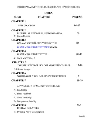
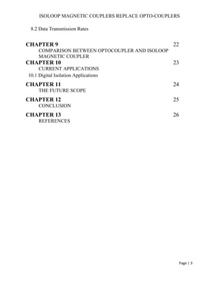
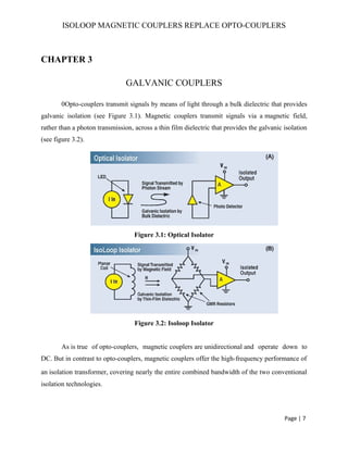
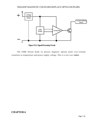
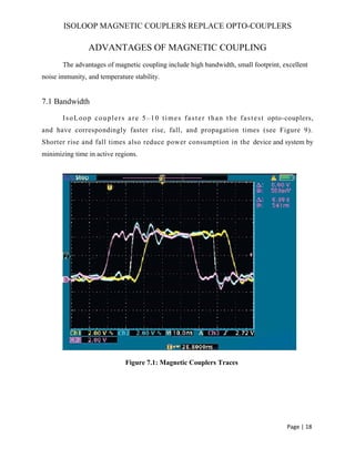
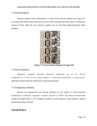
This document discusses magnetic couplers that can replace opto-couplers. Magnetic couplers use giant magneto resistance (GMR) materials and a planar coil to transmit signals magnetically across an insulating layer, providing galvanic isolation. They have advantages over opto-couplers like higher bandwidth, smaller size, better noise immunity, and temperature stability. The document provides details on the construction and working of magnetic couplers and their benefits in industrial applications.
Includes Introduction, Derivation of power flow through transmission line, Single line diagram of three phase transmission, methods of finding the performance of transmission line. 1.Analytical Method 2.Graphical method (circle diagram)., circle diagram of receiving end side and sending end side.
Wireless power transmission via Space Based Solar Powernikhil gaurav
this presentation tells about how the power is transmitting wireless and how it helps to decrease the losses in power transmission and thus increases efficiency and more important is uses a renewable source of energy(SUN).
These slides are all about Phasor Measurement Units (PMUs). An introduction to PMU is presented as a preliminary knowledge for the course 'Distribution Generation and Smart Grid'. Your valuable suggestions are welcome.
Seminar report on solar tree (by Vikas)dreamervikas
Now a days with the growing population and energy demand we should take a renewable option of energy source and also we should keep in mind that energy should not cause pollution and other natural hazards. In this case the solar energy is the best option for us.
so based on solar energy the solar tree is formed and it acquire very less land.
The electricity supply industry is undergoing a profound transformation worldwide. Market forces, scarcer natural resources, and an ever-increasing demand for electricity are some of the drivers responsible for such unprecedented change. Against this background of rapid evolution, the expansion programs of many utilities are being thwarted by a variety of well-founded, environment, land-use, and regulatory pressures that prevent the licensing and building of new transmission lines and electricity generating plants.
It’s a power electronics project. It is able to give output voltage(DC) more and less than input voltage as per requirement.
We can generate variable DC voltage which is less than input, but, the special things about this converter is, it has capability to produce variable DC voltage as high as twice the input voltage.
We have specially designed and manufactured inductor for this project.
A three-input hybrid system for solar car is designed in this project. It consists of one unidirectional input power port and two bidirectional power ports with a storage element. Depending on utilization state of the battery, three different power operation modes are defined for the converter. Battery charging in the system is carried out from the amorphous solar panel mounted on the body and a solar energy harvesting charging station. Since the solar energy is directly given to the DC load, the efficiency of the system will improve. The capacitor which is connected to the lead acid battery will charge at off peak hours and discharge during the acceleration time of the car. In this proposed system energy wasted in the brakes are also recovered and used to charge the lead acid battery. Hence competent Hybrid Electric Vehicle was developed by using super capacitor and regenerative braking scheme.
Effect of fiber and solenoid variation parameters on the elements of a correc...IJECEIAES
Controlling the polarization of the light output from single-mode fiber systems is very important for connecting it to polarization-dependent integrated optical circuits, while applications using a heterodyne detection system. Polarization controller using fiber squeezer is attractive for a lowloss, low-penalty coherent optical fiber trunk system. However, for polarization controllers using electromagnetic fiber squeezer, the stability problem due to the saturation of their magnetic circuit must be studied. In fact, in their conventional configuration, open-loop stability affects performance and limits applications. First at all, this effect has been analyzed and a feedback circuit with correctors has been proposed to improve stability performance. Then a simulation study is proposed to examine the influence of the system parameters on the corrector constants. The results of the simulation show that if the system parameters change the constants Kp, Ki and Kd of the PID corrector must be adjusted to keep an optimized dynamic response.
In our conventional electronic devices we use semi conducting materials for logical operation and magnetic materials for storage, but spintronics uses magnetic materials for both purposes. These spintronic devices are more versatile and faster than the present one. One such device is Spin Valve Transistors (SVT).
Spin valve transistor is different from conventional transistor. In this for conduction we use spin polarization of electrons. Only electrons with correct spin polarization can travel successfully through the device. These transistors are used in data storage, signal processing, automation and robotics with less power consumption and results in less heat. This also finds its application in Quantum computing, in which we use Qubits instead of bits.
Simulation study of single event effects sensitivity on commercial power MOSF...journalBEEI
High-frequency semiconductor devices are key components for advanced power electronic system that require fast switching speed. Power Metal Oxide Semiconductor Field Effect Transistor (MOSFET) is the most famous electronic device that are used in much power electronic system. However, the application such as space borne, military and communication system needs Power MOSFET to withstand in radiation environments. This is very challenging for the engineer to develop a device that continuously operated without changing its electrical behavior due to radiation. Therefore, the main objective of this study is to investigate the Single Event Effect (SEE) sensitivity by using Heavy Ion Radiation on the commercial Power MOSFET. A simulation study using Sentaurus Synopsys TCAD software for process simulation and device simulation was done. The simulation results reveal that single heavy ion radiation has affected the device structure and fluctuate the I-V characteristic of commercial Power MOSFET.
The ever-increasing use of high-frequency switching devices in industrial automation can result in high-frequency currents circulating in an equipotential bonding network that was not designed for this purpose. The absence of a proven low-impedance bonding network can result in these currents taking alternative and often undesirable routes. Occasionally these will be the shields of industrial network cables such as PROFIBUS and PROFINET that in turn can lead to intermittent communications problems. This presentation will discuss the issues in more detail and will explain the relevance of the recently released PI guidelines “Functional Bonding and Shielding for PROFIBUS and PROFINET”.
The basis for intelligent automation is communication. The increasing use of communication makes industry increasingly vulnerable for interference. This EMC lecture gives an insight on the disturbance mechanism based on real industrial cases and provides you solutions.
Student information management system project report ii.pdfKamal Acharya
Our project explains about the student management. This project mainly explains the various actions related to student details. This project shows some ease in adding, editing and deleting the student details. It also provides a less time consuming process for viewing, adding, editing and deleting the marks of the students.
Literature Review Basics and Understanding Reference Management.pptxDr Ramhari Poudyal
Three-day training on academic research focuses on analytical tools at United Technical College, supported by the University Grant Commission, Nepal. 24-26 May 2024
Cosmetic shop management system project report.pdfKamal Acharya
Buying new cosmetic products is difficult. It can even be scary for those who have sensitive skin and are prone to skin trouble. The information needed to alleviate this problem is on the back of each product, but it's thought to interpret those ingredient lists unless you have a background in chemistry.
Instead of buying and hoping for the best, we can use data science to help us predict which products may be good fits for us. It includes various function programs to do the above mentioned tasks.
Data file handling has been effectively used in the program.
The automated cosmetic shop management system should deal with the automation of general workflow and administration process of the shop. The main processes of the system focus on customer's request where the system is able to search the most appropriate products and deliver it to the customers. It should help the employees to quickly identify the list of cosmetic product that have reached the minimum quantity and also keep a track of expired date for each cosmetic product. It should help the employees to find the rack number in which the product is placed.It is also Faster and more efficient way.
Water billing management system project report.pdfKamal Acharya
Our project entitled “Water Billing Management System” aims is to generate Water bill with all the charges and penalty. Manual system that is employed is extremely laborious and quite inadequate. It only makes the process more difficult and hard.
The aim of our project is to develop a system that is meant to partially computerize the work performed in the Water Board like generating monthly Water bill, record of consuming unit of water, store record of the customer and previous unpaid record.
We used HTML/PHP as front end and MYSQL as back end for developing our project. HTML is primarily a visual design environment. We can create a android application by designing the form and that make up the user interface. Adding android application code to the form and the objects such as buttons and text boxes on them and adding any required support code in additional modular.
MySQL is free open source database that facilitates the effective management of the databases by connecting them to the software. It is a stable ,reliable and the powerful solution with the advanced features and advantages which are as follows: Data Security.MySQL is free open source database that facilitates the effective management of the databases by connecting them to the software.
Hierarchical Digital Twin of a Naval Power SystemKerry Sado
A hierarchical digital twin of a Naval DC power system has been developed and experimentally verified. Similar to other state-of-the-art digital twins, this technology creates a digital replica of the physical system executed in real-time or faster, which can modify hardware controls. However, its advantage stems from distributing computational efforts by utilizing a hierarchical structure composed of lower-level digital twin blocks and a higher-level system digital twin. Each digital twin block is associated with a physical subsystem of the hardware and communicates with a singular system digital twin, which creates a system-level response. By extracting information from each level of the hierarchy, power system controls of the hardware were reconfigured autonomously. This hierarchical digital twin development offers several advantages over other digital twins, particularly in the field of naval power systems. The hierarchical structure allows for greater computational efficiency and scalability while the ability to autonomously reconfigure hardware controls offers increased flexibility and responsiveness. The hierarchical decomposition and models utilized were well aligned with the physical twin, as indicated by the maximum deviations between the developed digital twin hierarchy and the hardware.
Harnessing WebAssembly for Real-time Stateless Streaming PipelinesChristina Lin
Traditionally, dealing with real-time data pipelines has involved significant overhead, even for straightforward tasks like data transformation or masking. However, in this talk, we’ll venture into the dynamic realm of WebAssembly (WASM) and discover how it can revolutionize the creation of stateless streaming pipelines within a Kafka (Redpanda) broker. These pipelines are adept at managing low-latency, high-data-volume scenarios.
Final project report on grocery store management system..pdfKamal Acharya
In today’s fast-changing business environment, it’s extremely important to be able to respond to client needs in the most effective and timely manner. If your customers wish to see your business online and have instant access to your products or services.
Online Grocery Store is an e-commerce website, which retails various grocery products. This project allows viewing various products available enables registered users to purchase desired products instantly using Paytm, UPI payment processor (Instant Pay) and also can place order by using Cash on Delivery (Pay Later) option. This project provides an easy access to Administrators and Managers to view orders placed using Pay Later and Instant Pay options.
In order to develop an e-commerce website, a number of Technologies must be studied and understood. These include multi-tiered architecture, server and client-side scripting techniques, implementation technologies, programming language (such as PHP, HTML, CSS, JavaScript) and MySQL relational databases. This is a project with the objective to develop a basic website where a consumer is provided with a shopping cart website and also to know about the technologies used to develop such a website.
This document will discuss each of the underlying technologies to create and implement an e- commerce website.
Saudi Arabia stands as a titan in the global energy landscape, renowned for its abundant oil and gas resources. It's the largest exporter of petroleum and holds some of the world's most significant reserves. Let's delve into the top 10 oil and gas projects shaping Saudi Arabia's energy future in 2024.
We have compiled the most important slides from each speaker's presentation. This year’s compilation, available for free, captures the key insights and contributions shared during the DfMAy 2024 conference.
6th International Conference on Machine Learning & Applications (CMLA 2024)ClaraZara1
6th International Conference on Machine Learning & Applications (CMLA 2024) will provide an excellent international forum for sharing knowledge and results in theory, methodology and applications of on Machine Learning & Applications.
Forklift Classes Overview by Intella PartsIntella Parts
Discover the different forklift classes and their specific applications. Learn how to choose the right forklift for your needs to ensure safety, efficiency, and compliance in your operations.
For more technical information, visit our website https://intellaparts.com
Governing Equations for Fundamental Aerodynamics_Anderson2010.pdf
ISOLOOP MAGNETIC COUPLERS REPLACED OPTOCOUPLERS
1. ISOLOOP MAGNETIC COUPLERS REPLACE OPTO-COUPLERS
ABSTRACT
Couplers, also known as "isolators" because they electrically isolate as well as transmit
data, are widely used in industrial and factory networks, instruments, and telecommunications.
Everyone knows the problems with opto-couplers. They take up a lot of space, are slow, opto-
couplers age and their temperature range is quite limited. For years, optical couplers were
the only option. Over the years, most of the components used to build instrumentation circuits
have become ever smaller. Opto-coupler technology, however, hasn’t kept up. Existing coupler
technologies look like dinosaurs on modern circuit boards. Magnetic couplers are analogous to
opto-couplers in a number of ways. Design engineers, especially in instrumentation technology,
will welcome a galvanically isolated data coupler with integrated signal conversion in a single
IC. My report will give a detailed study about ‘ISOLOOPMAGNETICCOUPLERS’.
Page | 1
2. ISOLOOP MAGNETIC COUPLERS REPLACE OPTO-COUPLERS
INDEX
SL NO CHAPTERS PAGE NO
CHAPTER 1
INTRODUCTION 04-05
CHAPTER 2
INDUSTRIAL NETWORKS NEED ISOLATION 06
2.1 Ground Loops
CHAPTER 3
GALVANIC COUPLERPHYSICS OF THE 07
GIANT MAGNETO RESISTANCE (GMR)
CHAPTER 4
GIANT MAGNETO RESISTIVE 08-12
4.1 GMR MATERIALS
CHAPTER 5
CONSTRUCTION OF ISOLOOP MAGNETICCOUPLER 13-16
5.1 Sensor Arrays
CHAPTER 6
WORKING OF A ISOLOOP MAGNETIC COUPLER 17
CHAPTER 7 18-19
ADVANTAGES OF MAGNETIC COUPLING
7.1 Bandwidth
7.2 Small Footprint
7.3 Noise Immunity
7.4 Temperature Stability
CHAPTER 8 20-21
DIGITAL ISOLATORS
8.1 Dynamic Power Consumption
Page | 2
3. ISOLOOP MAGNETIC COUPLERS REPLACE OPTO-COUPLERS
8.2 Data Transmission Rates
CHAPTER 9 22
COMPARISON BETWEEN OPTOCOUPLER AND ISOLOOP
MAGNETIC COUPLER
CHAPTER 10 23
CURRENT APPLICATIONS
10.1 Digital Isolation Applications
CHAPTER 11 24
THE FUTURE SCOPE
CHAPTER 12 25
CONCLUSION
CHAPTER 13 26
REFERENCES
Page | 3
4. ISOLOOP MAGNETIC COUPLERS REPLACE OPTO-COUPLERS
CHAPTER 1
INTRODUCTION
In many industrial control systems getting valuable data to its destination is often a
headache. Factors such as ground loops, noise, temperature extremes, and speed
bottlenecks can adversely affect data transmission. Opto-isolators have been until
recently the obvious solution, but their bulk, slow speed, high power consumption, and
limited temperature range now presents serious shortcomings for the designer.
A new generation of solid-state couplers IsoLoop magnetic couplers, has been
introduced which overcomes many Opto-coupler limitations. IsoLoop devices can be
combined with conventional integrated circuits to create single-package isolated
transceivers. Isolated transceivers are available in single 16-pin SOIC packages. These
devices support data rates as high as 40Mbps.IsoLoop couplers add an integrated
Insulating layer and a microscopic coil on top of a small sensor element bridge. A
magnetic field proportional to the input current signal is generated beneath the coil
winding. The resulting magnetic field is sensed across the dielectric film. The dielectric
provides 4,500 Volts DC of galvanic isolation Magnetic couplers are based on the Giant
Magneto resistance (GMR) effect, discovered by French scientists in 1988. GMR
materials are made from exotic metal alloys deposited in extremely thin layers and
formed into tiny resistors. The GMR resistors are sensitive to magnetic fields in the plane
of the substrate.
This enables a more compact integration scheme than would be possible with a
Hall sensor. The sensed magnetic field is amplified and conditioned with integrated
electronic circuits to produce an isolated replica of the input signal. Ground potential
Page | 4
5. ISOLOOP MAGNETIC COUPLERS REPLACE OPTO-COUPLERS
variations, however, are common to both sides of the input coil, so they do not generate a
current. Thus no magnetic field results and these variations are not sensed by the GMR
structures. In this way, the signal is transparently passed from the input to the output
circuits while ground potential variations are rejected to achieve a very large common-
mode rejection ratio (CMRR) and true galvanic isolation.
Page | 5
6. ISOLOOP MAGNETIC COUPLERS REPLACE OPTO-COUPLERS
CHAPTER 2
INDUSTRIAL NETWORKS NEED ISOLATION
2.1 Ground Loops
When equipment using different power supplies is tied together (with a common ground
connection) there is a potential for ground loop currents to exist. This is an induced current in the
common ground line as a result of a difference in ground potentials at each piece of equipment.
Normally all grounds are not in the same potential. Widespread electrical and communications
networks often have nodes with different ground domains. The potential difference between
these grounds can be AC or DC, and can contain various noise components. Grounds connected
by cable shielding or logic line ground can create a ground loop unwanted current
flow in the cable. Ground-loop currents can degrade datasignals, produce excessive EMI,
damage components, and, if the current is large enough, present a shock hazard. Galvanic
isolation between circuits or nodes in different ground domains eliminates these problems,
seamlessly passing signal information while isolating ground potential differences and common-
mode transients. Adding isolation components to a circuit or network is considered good design
practice and is often mandated by industry standards. Isolation is frequently used in
modems, LAN and industrial network interfaces (e.g., network hubs, routers, and switches),
telephones, printers, fax machines, and switched-mode power supplies.
Page | 6
7. ISOLOOP MAGNETIC COUPLERS REPLACE OPTO-COUPLERS
CHAPTER 3
GALVANIC COUPLERS
0Opto-couplers transmit signals by means of light through a bulk dielectric that provides
galvanic isolation (see Figure 3.1). Magnetic couplers transmit signals via a magnetic field,
rather than a photon transmission, across a thin film dielectric that provides the galvanic isolation
(see figure 3.2).
Figure 3.1: Optical Isolator
Figure 3.2: Isoloop Isolator
As is true of opto-couplers, magnetic couplers are unidirectional and operate down to
DC. But in contrast to opto-couplers, magnetic couplers offer the high-frequency performance of
an isolation transformer, covering nearly the entire combined bandwidth of the two conventional
isolation technologies.
Page | 7
8. ISOLOOP MAGNETIC COUPLERS REPLACE OPTO-COUPLERS
CHAPTER 4
PHYSICS OF THE GIANT MAGNETO RESISTANCE (GMR)
4.1 Giant Magneto resistive
Large magnetic field dependent changes in resistance are possible in thin film Ferro
magnet /nonmagnetic metallic multilayers. The phenomenon was first observed in France in 1988,
when changes in resistance with magnetic field of up to 70% were seen. Compared to the small
percent change in resistance observed in an isotropic magneto resistance, this phenomenon
was truly ‘giant’ magneto resistance. The spin of electrons in a magnet is aligned to
produce a magnetic moment. Magnetic layers with opposing spins (magnetic
moments) impede the progress of the electrons (higher scattering) through a sandwiched
conductive layer. This arrangement causes the conductor to have a higher resistance to current
flow. An external magnetic field can realign all of the layers into a single magnetic moment.
When this happens, electron flow will be less effected (lower scattering) by the uniform spins of
the adjacent ferromagnetic layers. This causes the conduction layer to have a lower
resistance to current flow. Note that these phenomenon takes places only when the
conduction layer is thin enough (less than5 nm) for the ferromagnetic layer’s electron spins to
affect the conductive layer’s electron’spath.
Page | 8
9. ISOLOOP MAGNETIC COUPLERS REPLACE OPTO-COUPLERS
Figure: 4.1.1
Figure: 4.1.2
Figure 4.1.A: NonmagneticConductiveLayers
The resistance of two thin ferromagnetic layers separated by a thin nonmagnetic
conducting layer can be altered by changing the moments of the ferromagnetic
layers from parallel to antiparallel, or parallel but in the opposite direction.
Layers with parallel magnetic moments will have less scattering at the
interfaces, longer mean free paths, and lower resistance. Layers with antiparallel magnetic
moments will have more scattering at the interfaces, shorter mean free paths, and higher
resistance (see Figure 4.1.1 & 4.1.2).
Page | 9
10. ISOLOOP MAGNETIC COUPLERS REPLACE OPTO-COUPLERS
Figure4.1.B:MagnetoResistiveSensor
For spin-dependent scattering to be a significant part of the total resistance, the layers
must be thinner than the mean free path of electrons in the bulk material. For many Ferromagnets
the mean free path is tens of nanometers, so the layers themselves must each be typically <10 nm
(100 Å). It is therefore not surprising that GMR was only recently observed with
the development of thin film depositionsystems.
The spins of electrons in a magnet are aligned to produce a magnetic moment. Magnetic layers
with opposing spins (magnetic moments) impede the progress of the electrons
(higher scattering) through a sandwiched conductive layer. This arrangement causes the
conductor to have a higher resistance to current flow.
Page | 10
11. ISOLOOP MAGNETIC COUPLERS REPLACE OPTO-COUPLERS
4.2 GMR MATERIALS
There are presently several GMR multilayer materials used in sensors and sensor arrays. The
following chart shows a typical characteristic for a GMR material:
Figure4.2:CharacteristicsofGMRMaterials
Notice that the output characteristic is Omni polar, meaning that the material provides the
same change in resistance for a directionally positive magnetic field as it does for a directionally
negative field. This characteristic has advantages in certain applications.
For example, when used on a magnetic encoder wheel, a GMR sensor using this material
will provide a complete sine wave output for each pole on the encoder thus doubling the resolution of
theoutputsignal.
Page | 11
12. ISOLOOP MAGNETIC COUPLERS REPLACE OPTO-COUPLERS
The material shown in the plot is used in most of GMR sensor products. It provides
a 98% linear output from 10% to 70% of full scale, a large GMR effect (13% to 16%), a stable
temperature coefficient (0.15%/°C) and temperature tolerance (+150°C), and a large magnetic
field range (0to 300 Gauss ).
For spin-dependent scattering to be a significant part of the total resistance, the layers
must be thinner than the mean free path of electrons in the bulk material. And many
ferromagnets the mean free path is tens of nanometers, so the layers themselves must each be
typically <10 nm (100 Å). It is therefore not surprising that GMR was only recently observed
with the development of thin film deposition systems.
CHAPTER 5
CONSTRUCTION OF ISOLOOP MAGNETICCOUPLER
Page | 12
13. ISOLOOP MAGNETIC COUPLERS REPLACE OPTO-COUPLERS
Figure5.1: IsolatorDataTravel
Figure 5.1 In a GMR, isolator data travels via a magnetic field through a dielectric
isolation to affect that resistance elements arranged in a bridge configuration.
Figure5.2:MagneticCoupler
To put this phenomenon to work, a Wheatstone bridge configuration of four GMR
sensors (see Figure 5.1 & 5.2). The manufacturing process allows thick film magnetic material to
be deposited over the sensor elements to provide areas of magnetic shielding or flux
concentration. Various op-amp or in-amp configuration scan be used to supply signal
conditioning from the bridge’s outputs. This forms the basis of an isolation receiver.
The isolation transmitter is simply coil circuitry deposited on a layer between the GMR
sensors layers and the thick film magnetic shielding layer (see Figure 5.1). Current through this
Page | 13
14. ISOLOOP MAGNETIC COUPLERS REPLACE OPTO-COUPLERS
coil layer produce the magnetic field, which overcomes the antiferromagnetic layers there by
reducing the sensor’s resistance.
5.1 Sensor Arrays
GMR elements can be patterned to form simple resistors, half bridges,
Wheatstone bridges, and even X-Y sensors. Single resistor elements are the smallest
devices and require the fewest components, but they have poor temperature
compensation and usually require the formation of some type of bridge by using
external components. Alternatively they can be connected in series with one differential
amplifier per sensor resistor. Half bridges take up more area on a chip but offer temperature
compensation, as both resistors are at the same temperature. Half bridges can be
used as field gradient sensors if one of the resistors is some distance from the
other. They can function as field sensors if one of the resistors is shielded from the applied field.
Figure 4 shows a portion of an array of 16 GMR half bridge elements with 5 µm spacing. The
elements are 1.5µm wide by 6 µm high with a similar size element above the
center tap. The bottoms of the stripes are connected to a common ground connection and the
tops of the half bridges are connected to a current supply. The center taps are connected to 16
separate pads on the die. A bias strap passes over the lower elements to provide
a magnetic field to bias the elements.
Page | 14
15. ISOLOOP MAGNETIC COUPLERS REPLACE OPTO-COUPLERS
5.1.1 Sensor Arrays
5.2 Signal Processing
Adding signal processing electronics to the basic sensor element increases the
functionality of sensors. The large output signal of the GMR sensor element Introduction
means less circuitry, smaller signal errors, less drift, and better temperature
stability compared to sensors where more amplification isrequiredtocreateausableoutput.
For the GMR products, we add a simple comparator and output transistor circuit to create
the world’s most precise digital magnetic sensor. For these products, no amplification of the
sensor’s output signal is necessary. A block diagram of this circuitry is shown in the figure 5.2.1.
Page | 15
16. ISOLOOP MAGNETIC COUPLERS REPLACE OPTO-COUPLERS
Figure5.2.1:SignalProcessingCircuit
The GMR Switch holds its precise magnetic operate point over extreme
variations in temperature and power supply voltage. This is a low cost method.
CHAPTER 6
Page | 16
17. ISOLOOP MAGNETIC COUPLERS REPLACE OPTO-COUPLERS
WORKING OF A ISOLOOP MAGNETIC COUPLER
In the Isoloop magnetic couplers, a signal at the input induces a current in a planar coil
(see figure no: 5).The current produces a magnetic field, which is proportional to the current
in the planar coil. The resulting magnetic field produces a resistance change in the GMR
material, which is separated from the planar coil by a high voltage insulating material. Since
the GMR is sensitive parallel to the plane of the substrate, this allows a considerably more comp
actconstruction than would be possible with Hall sensors. The resistance change in GMR
material, which was caused by the magnetic field, is amplified by an
electronic circuit and impressed upon the output as a reproduction of the input
signal. Since changes in the ground potential at the input, output or both doesn’t produce a
current in the planar coil, no magnetic field is created. The GMR material doesn’t change. In this
way safe galvanic signal isolation is achieved and at the same time a corresponding common mode
voltagetolerance.
CHAPTER 7
Page | 17
18. ISOLOOP MAGNETIC COUPLERS REPLACE OPTO-COUPLERS
ADVANTAGES OF MAGNETIC COUPLING
The advantages of magnetic coupling include high bandwidth, small footprint, excellent
noise immunity, and temperature stability.
7.1 Bandwidth
IsoLoop couplers are 5–10 times faster than the fastest opto-couplers,
and have correspondingly faster rise, fall, and propagation times (see Figure 9).
Shorter rise and fall times also reduce power consumption in the device and system by
minimizing time in active regions.
Figure 7.1: Magnetic Couplers Traces
Page | 18
19. ISOLOOP MAGNETIC COUPLERS REPLACE OPTO-COUPLERS
7.2 Small Footprint
IsoLoop couplers can be fabricated in <1 mm2 of die area per channel (see Figure 10).
Less board real estate means both more room for other functions and lower prices. Furthermore,
because of their small die size, IsoLoop couplers cost no more than high-performance opto-
couplers.
Figure 7.2: Four-Channel Magnetic Coupler Die
7.3 Noise Immunity
Magnetic couplers provide transient immunity up to 25 kV/µs,
compared to 10 kV/µs for optocouplers. Transient immunity is especiallyi
mportant in harsh industrial and process control environments.
7.4 Temperature Stability
Because the transmission and sensing elements are not subject to semiconductor
temperature variations, magnetic couplers operate to 100°C and above; for most opto-
couplers the upper limit is 75°C. Magnetic couplers are also immune to opto-couplers’ inherent
performance decay with age.
CHAPTER 8
Page | 19
20. ISOLOOP MAGNETIC COUPLERS REPLACE OPTO-COUPLERS
DIGITAL ISOLATORS
These devices offer true isolated logic integration in a level not previously
available. All transmit and receive channels operate at 110 Mbd over the full temperature and
supply voltage range. The symmetric magnetic coupling barrier provides a typical propagation
delay of only 10 ns and a pulse width distortion of 2 ns achieving the best specifications of any
isolator device. Typical transient immunity of 30 kV/µs is unsurpassed.
8.1 Dynamic Power Consumption
Isoloop devices achieve their low power consumption from the manner by
which they transmit data across the isolation barrier. By detecting the edge transitions of the
input logic signal and converting these to narrow current pulses, a magnetic field is
created around the GMR Wheatstone Bridge. Depending on the direction of the magnetic
field, the bridge causes the output comparator to switch following the input logic
signal. Power consumption is independent of mark-to-space ratio and solely dependent on
frequency. This has obvious advantages over opto-couplers whose power
consumption is heavily dependent on its on-state and frequency. The maximum power
supply current per channel for IsoLoop is:
I (input) =40(f/fmax) (4/5)mA
Where f=operating frequency
fmax= 50 MHz
8.2 Data Transmission Rates
Page | 20
21. ISOLOOP MAGNETIC COUPLERS REPLACE OPTO-COUPLERS
The reliability of a transmission system is directly related to the accuracy and
quality of the transmitted digital information. For a digital system, those parameters, which
determine the limits of the data transmission, are pulse width distortion and propagation,
delay skew.
Propagation delay is the time taken for the signal to travel through the device.
This is usually different when sending a low-to-high than when sending a
high-to-low signal. This difference, or error, is called pulse width distortion
(PWD) and is usually in ns. It may also be expressed as a percentage:
P W D % = ( Maximum Pulse Width Distortion (ns)/Signal Pulse Width (ns)) x 100%
Propagation delay skew is the difference in time taken for two or more channels to
propagate their signals. This becomes significant when clocking is involved since it is
undesirable for the clock pulse to arrive before the data has settled. A short propagation delay
skew is therefore critical, especially in high data rate parallel systems, to establish and
maintain accuracy and repeatability. The IsoLoop range of isolators all has a
maximum propagation delay skew of 6 ns, which is five times better than any opto-
coupler. The maximum channel to channel skew in the IsoLoop coupler is only 3 ns,
ten times better than any other opto-couplers.
CHAPTER 9
Page | 21
22. ISOLOOP MAGNETIC COUPLERS REPLACE OPTO-COUPLERS
COMPARISON BETWEEN OPTOCOUPLER ANDISOLOOP
MAGNETIC COUPLER
Unlike typical microsecond Ton/Toff times of opto-isolators, The IsoLoop-isolators also
have identical TON/TOFF times, which produce no pulse-w i d t h d i s t o r t i o n a s
i s t h e c a s e w i t h m a n y o p t o - i s o l a t o r s h a v i n g d i f f e r i n g Ton/Toff
times. Propagation delays are less than 10 ns with inter-channel skewing of
less than 2 ns. Isoloop-isolators have up to four channels per package in a variety of device
direction configurations. These standard devices are great for bus isolation,
serial ADCs and DACs, and communication isolation. The working range
of opto-couplers is only between zero and ten megahertz. The IsoLoop
couplers have data transmission speeds up to100 mega baud. IsoLoop devices will
operate over a wide temperature range of -40 to +100C, compared with the restricted
range of 0 to +70C for opto-isolators. The power consumption of IsoLoop devices is solely
dependent on frequency. This makes for lower power consumption than opto-isolators, whose
power consumption is heavily dependent on state and frequency. With data rates up to
100Mbaud, the IsoLoop technology offers rates of up to ten times that of opto-isolators.
CHAPTER 10
Page | 22
23. ISOLOOP MAGNETIC COUPLERS REPLACE OPTO-COUPLERS
CURRENT APPLICATIONS
Magnetic isolators are quickly finding their way into process control and industrial
applications. Isolation of A/D interfaces is one popular use.
Inaddition, magnetic isolators’ combination of speed and packaging densit
y provides a good method of efficient data channel management when multiple A/Ds need to
be interfaced on the same circuit card. A four-channel part with three channels
going one way and one going the other is available for A/D interface
applications. Magnetic couplers also enable higher speed factory networks
such as Profibus and other protocols. These devices are great for bus isolation, serial
ADCs and DACs, and communication isolation. The combination of the fast and high-
density IsoLoop couplers with high packing density allow sufficient data channel
management where several A/D channels must be isolate don a board.
10.1 Digital Isolation Applications
ADCs
DACs
Multiplexed Data Transmission
Data Interfaces
Digital Noise Reduction
Ground Loop Elimination
CHAPTER 11
Page | 23
24. ISOLOOP MAGNETIC COUPLERS REPLACE OPTO-COUPLERS
THE FUTURE SCOPE
Magnetic field detection has vastly expanded as industry has used
avariety of magnetic sensors to detect the presence, strength, or direction
of magnetic fields from the Earth, permanent magnets, magnetized soft magnets, and the
magnetic fields associated with current. These sensors are used as proximity sensors, speed and
distance measuring devices, navigation compasses, and current sensors. They can measure these
properties without actual contact to the medium being measured and have become the eyes of
many control systems.
CHAPTER 12
Page | 24
25. ISOLOOP MAGNETIC COUPLERS REPLACE OPTO-COUPLERS
CONCLUSION
Magnetic couplers will in time be even faster and have more channels. More types of
integrated bus transceivers will be available. Several manufacturers are planning to
introduce magnetic couplers. The U.S. military is providing significant
funding for advanced magnetics coupler development because of the value of their
high speed and noise immunity in aircraft and other systems. It has reported prototype devices
with speeds of 300 Mbaud and switching times of <1ns. Also under development are higher-
density parts (full byte-wide couplers) and more functionality (latching bus transceivers).
Finally, the inherent linearity of are sensitive coil and resistive sensing elements make magnetic
couplers well suited for linear data protocols such as low-voltage differential signaling.
CHAPTER 13
Page | 25
26. ISOLOOP MAGNETIC COUPLERS REPLACE OPTO-COUPLERS
REFERENCES
1. J.Daughton and Y. Chen. "GMR Materials for Low Field
Applications, "IEEE Trans Magn, Vol. 29:2705-2710, 2003.pp.18-21
2. Michael J. Caruso, Tamara Bratland, C. H. Smith, and Robert
Schneider, “A New Perspective on Magnetic Field Sensing,” Sensors Magazine,
vol.15, no. 12, (December 2002), pp. 34-46
3. Carl H. Smith and Robert W. Schneider, “Low-Field Magnetic
Sensingwith GMR Sensors, Part 1: The Theory of Solid-State Sensing,” Sensors
Magazine, vol. 16, no. 9, (September 2002), pp. 76-83.
4. Carl H. Smith and Robert W. Schneider, “Low-Field Magnetic
Sensingw i t h G M R S e n s o r s , P a r t 2 : G M R S e n s o r s a n d t h e i r A p
p l i c a t i o n s , ” Sensors Magazine, vol. 16, no. 10, (October 2002), pp. 84- 91.
5. http://www.circuitcellar.com/library/print/0502/JEFF/4.asp
6 . h t t p : / / w w w . s e n s o r s m a g . c o m /
7. http://www.nve.com/isoloop/news/hispdnr.php
8. http://www.electronicstalk.com/news/rho/rho000.html
Page | 26