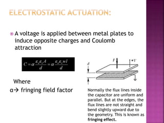
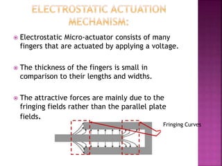
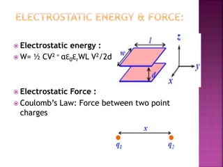
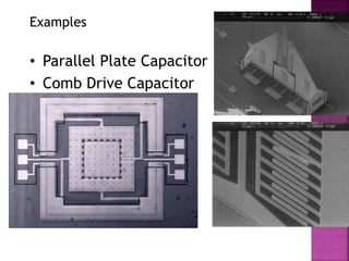
NIMI T
2nd Year MTech ECE
Pondicherry University
 It stands for micro electro mechanical
systems
 It is the integration of elements sensors
actuators and electronics on a common
silicon substrate
 Micro fabrication technology, for making
microscopic devices
 The actuator is an element which applies a
force to some object through a distance
 Various actuation mechanisms:
- Electrostatic actuation
-Thermal actuation
-Piezoelectric actuation
-Magnetic actuation
 A voltage is applied between metal plates to
induce opposite charges and Coulomb
attraction
Where
α fringing field factor Normally the flux lines inside
the capacitor are uniform and
parallel. But at the edges, the
flux lines are not straight and
bend slightly upward due to
the geometry. This is known as
fringing effect.
 Electrostatic Micro-actuator consists of many
fingers that are actuated by applying a voltage.
 The thickness of the fingers is small in
comparison to their lengths and widths.
 The attractive forces are mainly due to the
fringing fields rather than the parallel plate
fields.
Fringing Curves
 Electrostatic energy :
 W= ½ CV2 = αƐ0ƐrWL V2/2d
 Electrostatic Force :
 Coulomb’s Law: Force between two point
charges
 Low power dissipation.
 Can be designed to dissipate no power while
exerting a force.
 High power density at micro scale.
 Easy to fabricate.
 Scaling
 Noise & Efficiency
 Range of force, motion and frequency
 Repeatability
 Nonlinearity
MASS
UIUC
Examples
• Parallel Plate Capacitor
• Comb Drive Capacitor
 assume that the electrical field is uniform
between the plates of the capacitor, and
zero outside
 uniform electric field between the plates has
the magnitude
E=Q/εA
 where A is the area of one capacitor plate, and Q is the
magnitude of the charge on each plate
 voltage across the capacitor is the product of
the E-field and the gap
V = gE = gQ /ƐA
 the capacitance is the ratio of the charge
and
the voltage
C=Q/V = ƐA/ g
When the capacitor plates are fixed
The stored energy in the capacitor is given by
Fixed gap
Increasing charge
Charging the capacitor at zero gap and
lifting
 At zero gap, the electrical stored energy is zero
 The force between two plates with opposite charges +Q
and –Q depends on electric field setup by charges
 This field is
Ɛ= Q/εA
 The corresponding force is
F= (Q/2)Ɛ =Q2/2ƐA  This force is independent of g
 Now we pull upper plate by distance g
W(g) = F*g
= Q2g/2ƐA
Charge fixed,
Increasing gap
• Stored energy
• Force is derivative of energy with
respect to pertinent dimensional
variable
• Plug in the expression for capacitor
• We arrive at the expression for
force
C
Q
CVU
2
2
2
1
2
1

2
2
1
V
d
C
d
U
F






d
A
d
A
Q
Q
C



d
CV
V
d
A
d
U
F
2
2
2
2
1
2
1





 As the voltage bias increases from zero
across a pair of parallel plates, the distance
between such plates would decrease until
they reach 2/3 of the original spacing, at
which point the two plates would be
suddenly snapped into contact.
 This behavior is called the pull-in effect.
Actuation in mems
Actuation in mems
Actuation in mems

Actuation in mems

  • 1.
    NIMI T 2nd YearMTech ECE Pondicherry University
  • 2.
     It standsfor micro electro mechanical systems  It is the integration of elements sensors actuators and electronics on a common silicon substrate  Micro fabrication technology, for making microscopic devices
  • 3.
     The actuatoris an element which applies a force to some object through a distance  Various actuation mechanisms: - Electrostatic actuation -Thermal actuation -Piezoelectric actuation -Magnetic actuation
  • 5.
     A voltageis applied between metal plates to induce opposite charges and Coulomb attraction Where α fringing field factor Normally the flux lines inside the capacitor are uniform and parallel. But at the edges, the flux lines are not straight and bend slightly upward due to the geometry. This is known as fringing effect.
  • 6.
     Electrostatic Micro-actuatorconsists of many fingers that are actuated by applying a voltage.  The thickness of the fingers is small in comparison to their lengths and widths.  The attractive forces are mainly due to the fringing fields rather than the parallel plate fields. Fringing Curves
  • 7.
     Electrostatic energy:  W= ½ CV2 = αƐ0ƐrWL V2/2d  Electrostatic Force :  Coulomb’s Law: Force between two point charges
  • 8.
     Low powerdissipation.  Can be designed to dissipate no power while exerting a force.  High power density at micro scale.  Easy to fabricate.
  • 9.
     Scaling  Noise& Efficiency  Range of force, motion and frequency  Repeatability  Nonlinearity
  • 10.
    MASS UIUC Examples • Parallel PlateCapacitor • Comb Drive Capacitor
  • 11.
     assume thatthe electrical field is uniform between the plates of the capacitor, and zero outside  uniform electric field between the plates has the magnitude E=Q/εA  where A is the area of one capacitor plate, and Q is the magnitude of the charge on each plate  voltage across the capacitor is the product of the E-field and the gap V = gE = gQ /ƐA  the capacitance is the ratio of the charge and the voltage C=Q/V = ƐA/ g
  • 12.
    When the capacitorplates are fixed The stored energy in the capacitor is given by Fixed gap Increasing charge
  • 13.
    Charging the capacitorat zero gap and lifting  At zero gap, the electrical stored energy is zero  The force between two plates with opposite charges +Q and –Q depends on electric field setup by charges  This field is Ɛ= Q/εA  The corresponding force is F= (Q/2)Ɛ =Q2/2ƐA  This force is independent of g  Now we pull upper plate by distance g W(g) = F*g = Q2g/2ƐA Charge fixed, Increasing gap
  • 14.
    • Stored energy •Force is derivative of energy with respect to pertinent dimensional variable • Plug in the expression for capacitor • We arrive at the expression for force C Q CVU 2 2 2 1 2 1  2 2 1 V d C d U F       d A d A Q Q C    d CV V d A d U F 2 2 2 2 1 2 1     
  • 15.
     As thevoltage bias increases from zero across a pair of parallel plates, the distance between such plates would decrease until they reach 2/3 of the original spacing, at which point the two plates would be suddenly snapped into contact.  This behavior is called the pull-in effect.